
Related Manuals for Mean Well DRS Series


Summary of Contents for Mean Well DRS Series
- Page 1 Series User Manual Load Modbus DATA PROTOCOL Power Supply Charger Back-up AC Grid DRS 240 480 Series Battery Pack All-in-one Multi-function Security Power Supply...
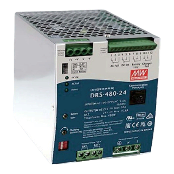
- Page 2 The DRS series is a DIN-rail type, digital security power supply launched by MEAN WELL. It integrates DC output, battery charge, uninterruptible power source (DC-UPS) and Modbus digital communication in tiny dimensions, thanks to microelectronics. The DRS series accepts the universal input between 90VAC and 305VAC.
-
Page 3: Table Of Contents
Content: Safety Guidelines 5 7 . Battery Start by Force Button Introduction Battery temperature . 2 1 Model number compensation . 2 2 Features ower boost mode . 2 3 Main specification Restore actory . 2 4 Safety overview efault etting 2 5 . -
Page 4: Safety Guidelines
Safety Guidelines Introduction Risk of electrical shock and energy hazard.Allfailure should be examined Model number by a qualified technician.Please do not remove the case of the power DRS - 240 - 48 supply by yourself. Risk of electrical arcs and electric shock(danger to life).Connecting both Function option (Blank: Built in... - Page 5 2. 3 Electrical Specification DRS-240 Series DRS-480 Series DRS-480-24 DRS-480-36 DRS-480-48 MODEL DRS-240-12 DRS-240-24 DRS-240-36 DRS-240-48 MODEL OUTPUT VOLTAGE OUTPUT VOLTAGE Note.2 Note.2 0 ~ 20A 0 ~ 10A 0 ~ 6.6A 0 ~ 5A 0 ~ 20A 0 ~ 13.3A 0 ~ 10A CURRENT RANGE LOAD CURRENT RANGE...
-
Page 6: Safety Overview
2. 4 Safety Overview 2. 6 Mechanical Specification ( DRS-240 Series ) 85.5 UL62368-1 BS EN/EN62368-1 AS/NZS 62368.1 TPTC004 IEC62368-1 (Pending) 2. 5 Derating Curve 129.2 1 2 3 4 5 6 7 8 9 10 1112 1 2 3 4 +V +V -V -V CN12 DC OK... -
Page 7: Installation & Wiring
Installation & Wiring ( DRS-480 Series ) 3 1 . Installation Methods 150.7 1 2 3 4 1 2 3 4 5 6 7 8 9101112 +V +V AC Fail DC OK Battery Charger Fail CN12 Admissible DIN rail:TS35/7.5 TS35/15 DC OK AC Fail Communication... -
Page 8: 2 Installation Procedures
3 4 . Battery Selection 3 2 . Installation Procedures Step 1. Please connect AC input cables, DC output cables, battery Battery types: Lead acid or lithium ion batteries charging cables, and RJ-45 communication cables(if used) Battery capacity: Please refer to the following table to the terminal blocks of this product. -
Page 9: User Interface Panel
User Interface Panel Cable selection and suggested torque: Panel Description Terminals Input(G) Output(A) Battery(F) Control pin(C) Suggested Suggested Suggested Suggested Series Wire Wire Wire Wire Torque Torque Torque Torque DRS-240 1 -2 AWG 5Kgf-cm 1 -2 AWG 5 7 . Kgf-cm 1 -2 AWG 5 7 . -
Page 10: Led Indicator
4 3 . LED Indicator Explanation of Setting DRS series integrates multi-functions in tiny dimension, including DC Indicator Description LED indicator o u t p u t p o we r, ba t te r y c h a rg i n g , D C - U P S a n d c o m m u n i c a t i o n DC fail m o n i t o r i n g . -
Page 11: 5.2 Dc-Ups
5.2 DC-UPS 5.3.1 2-stage charging (DIP switch on “2”stage) 5.2.1. When AC mains drops below :79~89VAC of 120VAC , 132~187VAC 220VAC UPS function will activate and power source switch battery backup. In the initial stage of charging, the charger charges the battery with the Note: From AC to battery, switch period is within 10ms. - Page 12 Start Built-in 2-stage charging curves boost DRS-240 DRS-480 float Charging DIP SW 12V model 24V model DIP SW voltage Description (default) boost Description (default) boost 100% CC Default, programmable 14.4 Default, programmable 28.8 Pre-defined, Gel battery 14.0 Pre-defined, Gel battery 28.0 15.4A 15.4A...
- Page 13 Time out SBP- 001 is a smart battery charging programmer developed by Model selection MEAN WELL, which can set the charging curves of the DRS series through editing software. SBP-001 provides functions such as Communication Monitoring Function charging curve adjustment and battery temperature compensation.
- Page 14 5 4 1.2 Communication nterface Device address Between A0/A1 and GND Device No. Iogic (Single) Min. request period (Controller to PSU/CHG): 50mSec。 Max. response time (PSU/CHG to Controller): 12.5mSec。 Open Short Min. packet margin time (Controller to PSU/CHG): 12.5mSec。 Request period (...
- Page 15 The following is data description of register addresses. Taper current setting 0x03、 CURVE_TC 0x00B3 Refer to 5 4 4 # of (only for charger) 0x06 Function Register data Command Name Description Value unit address code 0x03、 Refer to transmission Configuration setting Bytes CURVE_CONFIG 0x00B4...
- Page 16 Transmission data description: Bit 7 HI_TEMP: High ambient temperature protection The conversion of setting and reading values is defined as following: 0=Normal ambient temperature Actual value= Communication reading value × F actor (F value). 1=Abnormal ambient temperature Among them Factor needs to refer to the definition of SCALING_FACTOR High byte: Bit 0:7 in each model list.
- Page 17 ◎ CURVE_CONFIG 0x00B4 (only for charger) : ◎ MFR REVISION_B0B5( 0x008C 0x008E is the firmware version. Arange of hexadecimal 0x00(R00.0)~0xFE(R25.4) represents the Bit7 Bit6 Bit5 Bit4 Bit3 Bit2 Bit1 Bit0 firmware version of an MCU; 0xFF represents no MCU existed. High byte FV TOE CV TOE...
- Page 18 ◎ CHG_STATUS 0x00B8 (only for charger) : Bit 5 CCTOF: Time out flag of constant current mode 0=NO time out in constant current mode Bit7 Bit6 Bit5 Bit4 Bit3 Bit2 Bit1 Bit0 1=Constant current mode time out High byte FV TOF CV TOF CCTOF BUFFTOF...
- Page 19 ◎ SCALING_FACTOR( 0x00C0 0x00C2 ): Byte1: Bit 0:3 VIN Factor:The factor of AC input voltage Bit7 Bit6 Bit5 Bit4 Bit3 Bit2 Bit1 Bit0 0x0=Not support AC input relevant commands Byte 5 Reserved Reserved 0x1~0x3=Currently not in use, retain (default is 0) Bit7 Bit6 Bit5...
- Page 20 Low byte: Bit 4:7 CURVE_TIMEOUT Factor:The factor of CC/CV/Float timeout Bit 0 M/S:Parallel mode(Not support) 0x0=Not support CURVE_TIMEOUT relevant commands 0=Slave 0x1~0x3=Currently not in use, retain (default is 0) 1=Master 0x4=0.001 Bit 1 DC_OK:Secondary DC output voltage status 0x5=0.01 0=Secondary DD output voltage status TOO LOW 0x6=0.1 1=Secondary DD output voltage status NORMAL 0x7=1.0...
- Page 21 5.4.2 Communication examples Low byte: Bit 0 MOD_CTRL:Modbus control status (Not support) The following provides examples of request and response for each 0=SVR function code of the Modbus RTU. 1=Modbus (VOUT_SET, IOUT_SET, OPERATION) 5.4.2.1 Read Holding Register FC=03 ( ) Bit 1:2 OPERATION_INIT:Pre-set value of power on operation command The request message specifies the starting register and quantity...
-
Page 22: Communication
Request: 5 4 3 CANBus communication 0x83 0x04 0x00 60 0x00 01 0x2F F6 Physical layer This protocol complies with CAN ISO-11898, and baud rate is 0x83 Slave ID 3 : 250Kbps. 0x04:Function code 4(Read analog input registers) Protocol frame format 0x00 60:The data address of the first register requested The protocol complies with CAN 2.0B, the extended frame format. - Page 23 5. . . 4 3 2 CANBus command list Manufacture serial 0x0087 MFR_SERIAL_B0B5 number # of data Command Command Transaction Description 0x0088 MFR_SERIAL_B6B11 Manufacture serial Name Type Code Bytes number Constant current setting 0x0000 OPERATION 0x00B0 CURVE_CC Remote ON/OFF (format: Output voltage set 0x0020 VOUT_SET...
- Page 24 ◎ FAULT_STATUS 0x0040 ): 0x00D4 READ_IBAT Charging or discharging current of battery Bit7 Bit6 Bit5 Bit4 Bit3 Bit2 Bit1 Bit0 (format: High byte Reserved Reserved Reserved Reserved Reserved Reserved Reserved value, F=0.01) Low byte OP_OFF AC_FAIL SHORT FAN_FAIL 0x00D5 READ_BAT_TEMPERATURE Temperature of battery Low byte: (format:...
- Page 25 ◎ MFR_ID_B0B5( 0x0080 is the first 6 codes of the manufacturer s name The power supply has MCUs. The firmware version of the MCU number 1 is version R 01.3 ), the MCU number 2 is (ASCII) MFR_ID_B6B11( 0x0081 is the last 6 codes of the manufacturer s name version R 01.2 ), the MCU number 3 is version R01.
- Page 26 Low byte: Low byte: Bit 0:1 CUVS :Charge Curve Selection Bit 0 FULLM:Fully charged mode status 00=Customized charge curve (default) 0=NOT fully charged 01=Gel battery 1=Fully charged 10=Flooded battery Bit 1 CCM:Constant current mode status 11=AGM battery 0=The charger NOT in constant current mode Bit 2:3 TCS:Temperature Compensation Setting 1=The charger in constant current mode...
- Page 27 Low byte: Bit 7 FVTOF:Time out flag of float mode Bit 0 M/S:Parallel mode(Not support) 0=NO time out in float mode 0=Slave 1=Float mode time out 1=Master Note: Not support settings display with “0” Bit 1 DC_OK:Secondary DC output voltage status 0=Secondary DD output voltage status TOO LOW Diagram of charging curve: 1=Secondary DD output voltage status NORMAL...
- Page 28 Low byte: 5. . 4 4 Range and tolerance of values Bit 0 _CTRL: CANBus control status (Not support) ( ) 1 Reading parameters 0=SVR CANBus /Modbus Command Model Range Tolerance 1= (VOUT_SET, IOUT_SET, OPERATION) 0x0050 READ_VIN 80 ~305V ±2V Bit 1:2 OPERATION_INIT:Pre-set value of power on operation command 0 ~15V...
-
Page 29: Alarm Signals
Alarm Signals 4 ~ 20A ±0.2A 2 ~ 10A ±0.1A Alarm signals: AC Fail, DC OK, Battery ow , bnormality, isconnection DRS-240 1.32 ~ 6.6A ±0.066A 6.6A of batteries, and Charger Fail. 0x00B0 CURVE_ICHG 1 ~ 5A ±0.05A 4 ~ 20A ±0.2A Battery low/Abnormal DRS-480... -
Page 30: 5.6 Battery Start By Battery Start Button
5.5.2 DC OK signal 1 2 3 4 1 2 3 4 5 6 7 8 91011 12 1 2 3 4 5 6 7 8 9 10 11 12 +V +V -V -V CN12 DC OK AC Fail AC Fail DC OK Battery Charger... -
Page 31: Battery Temperature
5 8 1 . . . CANBus and Modbus commands can modify parameters of 5.7.1 Short-circuit PIN 7 and PIN 8 of CN12 together to activate the mode (after activation, it is recommended to disconnect the connection in temperature compensation. There are four selections, Disable, order not to interfere in the function of 5.7.2) Short circuit on PIN7 -3mV/℃/Cell, 4mV/℃/Cell and 5mV/℃/Cell, and default and PIN8 of CN12(Open or remain shorted). -
Page 32: P Ower Boost Mode
Power oost Load 5.9.1 No battery connection Power supply can remain 115% of rated power, then shut down after 5 sec. 5.9.2 With battery connected The maximum current on the load output is the 2 times the rated current for 4 minutes max. 10 min time Do not exceed 6 seconds in 10 minute cycle. -
Page 33: Protection And
41 8±1.0V Note:1. Refer to chapter 4.3 for LED indicator. Note: If battery under-voltage protection is triggered by force 2. Please contact MEAN WELL s distributor if above button, please refer to 5.7.3. faulty condition is not removable. -
Page 34: Warranty
※ MEAN WELL possess the right to adjust the content of this manual. Please refer to the latest version of our manual on our website. - Page 35 N o . 2 8 , W u q u a n 3 r d R d . , W u g u D i s t . , N e w Ta i p e i C i t y 2 4 8 , Ta i w a n...
Need help?
Do you have a question about the DRS Series and is the answer not in the manual?
Questions and answers