Table of Contents
Advertisement
Quick Links
Type:
DR-RDN20 DIN rail peripheral
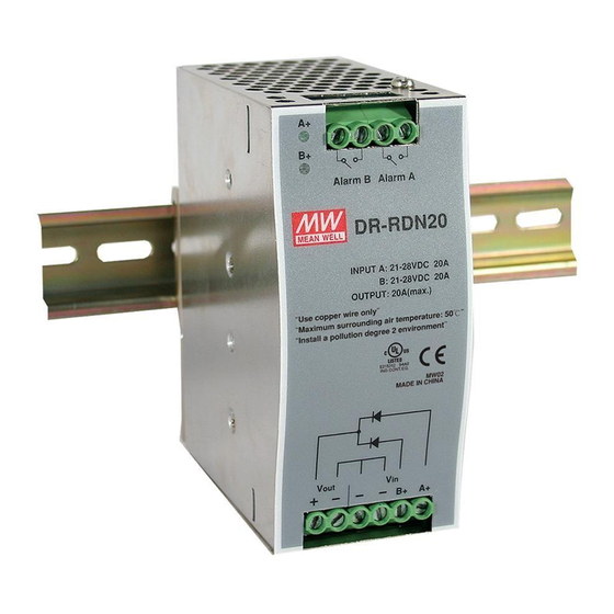
DR-RDN20
Introduction
DR-RDN20 is a DIN rail peripheral for the redundant module.
Like other Mean Well's DIN series, they can be mounted on a TS35 Standard DIN rail.
Installation
(1)Always allow good ventilation clearances, 5mm left and right, 40mm above and 20mm below, around the unit
in use to prevent it from overheating. Also a 10-15 cm clearance must be kept when the adjacent device is a
heat source.
(2)The appropriate mounting orientation for the unit is vertical, the TB1 terminals at the bottom. Mounting
orientations other than that, such as upside down, horizontal, or table-top mounting, is not allowed.
(3)Use copper wire only, and recommended wires are shown as below.
AWG
Rated Current of
Equipment (Amp)
Cross-section of
2
Lead(mm
)
Note: 1. Current each wire carries should be de-rated to 80% of the current suggested
above when using 5 or more wires connected to the unit.
2. The maximum allowable wire cross-sectional area for the terminal is 10 AWG/
5.3 mm
Make sure that all strands of each stranded wire enter the terminal connection and the screw terminals are
securely fixed to prevent poor contact. If the power supply possesses multi-output terminals, please make
sure each contact is connected to wires to prevent too much current stress on a single contact.
(4)Use wires that can withstand temperatures of at least 80°C, such as UL1007.
(5)Recommended wire strapping length is 5mm (0.197").
(6)Recommended screwdriver is 4mm, slotted type.
(7)The recommended torque setting for terminals is 10kgf-cm(9Lb-in).
Installation Manual
INPUT:A:21-28VDC 20A
B:21-28VDC 20A
18
7A
10A
0.8
2
.
OUTPUT:20A (max)
16
14
15A
1.3
2.1
12
10
20A
30A
3.3
5.3
Advertisement
Table of Contents

Related Manuals for Mean Well DR-RDN20


Summary of Contents for Mean Well DR-RDN20
- Page 1 Introduction DR-RDN20 is a DIN rail peripheral for the redundant module. Like other Mean Well’s DIN series, they can be mounted on a TS35 Standard DIN rail. Installation (1)Always allow good ventilation clearances, 5mm left and right, 40mm above and 20mm below, around the unit in use to prevent it from overheating.
- Page 2 Installation Manual (8)Mounting Instruction: Mount as shown in figure only, with input terminals down, or else sufficient cooling will not be possible. Admissible DIN rail:TS35/7.5 or TS35/15 For rail fastening: (a)Tilt the unit slightly rearwards. (b)Fit the unit over top hat rail. (c)Slide it downward until it hits the stop.
- Page 3 Installation Manual Manufacturer: MEAN WELL ENTERPRISES Co., LTD. No.28, Wuquan 3rd Rd., Wugu Dist., New Taipei City 24891, Taiwan Tel: +886-2-2299-6100 Web: www.meanwell.com Branch Office: China U.S.A. Europe MEAN WELL (GUANGZHOU) MEAN WELL USA, INC. MEAN WELL EUROPE B.V. ENTERPRISES Co., LTD.
- Page 4 In order to reduce the impacts on the environment and take the more responsibility for protecting the earth, MEAN WELL is confirming and announcing the conformity to China RoHS, an Administrative Measures for the Restriction of the Use of Hazardous Substances in Electrical and Electronic Products.
Need help?
Do you have a question about the DR-RDN20 and is the answer not in the manual?
Questions and answers