Table of Contents
Advertisement
Quick Links
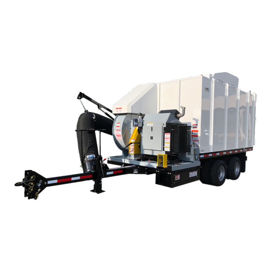
DCL800TM
DCL800TM
Self Contained Leaf Collector
Self Contained Leaf Collector
Owner's Manual
Safety Manual
Pre-Operating Manual
Operating Manual
Maintenance Manual
Service Manual
Parts Catalog
2020 Edition
ODB Company
5118 Glen Alden Drive
Richmond, VA 23231
800-446-9823
DCL800TM
ODB Company
DCL800TM
1
Advertisement
Table of Contents
Troubleshooting

Related Manuals for ODB DCL800TM


Summary of Contents for ODB DCL800TM
-
Page 1: Dcl800Tm
DCL800TM DCL800TM Self Contained Leaf Collector Self Contained Leaf Collector Owner's Manual Safety Manual Pre-Operating Manual Operating Manual Maintenance Manual Service Manual Parts Catalog 2020 Edition ODB Company 5118 Glen Alden Drive Richmond, VA 23231 800-446-9823 DCL800TM ODB Company DCL800TM... - Page 2 READING AND UNDERSTANDING THIS MANUAL IF YOU HAVE ANY QUESTIONS CONCERNING THE INSTALLATION OR OPERATION OF THIS UNIT, PLEASE CALL ODB FOR ASSISTANCE BEFORE ATTEMPTING TO REPAIR OR OPERATE THE UNIT. IMPROPER USE OF ANY MACHINE CAN RESULT IN SERIOUS INJURY!
- Page 3 Read and understand this entire manual before operating, maintain- ing or repairing the leaf vacuum. If the decal above is missing or damaged call ODB immediately and we will send you a replacement free of charge. Never operate a unit with damaged or missing safety decals.
- Page 4 Since 1910 THANK YOU Thank you and Congratulations on your puchase of your ODB Leaf Collector. Your ODB leaf col- lector has been carefully designed and manufactured to give you a maximum amount of dependabil- ity and years of trouble-free operation. Take comfort in the fact the ODB has been manufacturing municipal products since 1910 and takes pride in our product's quality and our customer service.
-
Page 5: Table Of Contents
TABLE OF CONTENTS Read and understand this entire manual before operating, maintaining or repair- ing the leaf vacuum. Table of Contents Contents DCL800TM..............................1 Table of Contents ............................5 1.0 GENERAL SAFETY 1.1 Safety Symbol Definitions ........................10 1.2 Do’s and Do Not’s:..........................11 1.3 Training: ..............................13... - Page 6 6.10 Kubota Exhuast Component Group ......................101 6.11 Battery Group ............................102 6.12 Remote Clutch ............................103 6.13 Chaffe Eliminator Assembly, hinged ...................... 104 7.0 CLUTCH GROUP 7-0 ................................... 105 7.1 AutoHD PTO Clutch Group ........................106 ODB Company DCL800TM...
- Page 7 11.3 Brake Assembly Group ..........................135 11.4 Axle Hub Assembly Group ........................136 12.0 HOSE BOOM GROUP 12-0 ................................... 137 12.1 Boom Group.............................. 138 12.2 Intake Hose Group ............................ 139 12.3 M3219 Hydraulic Boom Pump ......................... 140 Index ................................. 142 ODB Company DCL800TM...
-
Page 8: General Safety
Read and understand this entire manual before operating, maintain- ing or repairing the leaf vacuum. GENERAL SAFETY 1.0 GENERAL SAFETY Contents DCL800TM......................1 Table of Contents ....................5 1.0 GENERAL SAFETY 1.1 Safety Symbol Definitions ................10 1.2 Do’s and Do Not’s:..................11 1.3 Training: ......................13 1.4 Safety Decals .....................14... - Page 9 Read and understand this entire manual before operating, maintain- ing or repairing the leaf vacuum. If the decal above is missing or damaged call ODB immediately. Never operate a unit with damaged or missing safety decals. DO NOT RIDE, SIT OR STAND ON UNIT DO NOT MODIFY THE UNIT FOR RIDERS IN ANY WAY.
-
Page 10: Safety Symbol Definitions
Disregarding this safety warning WILL result in serious equipment damage, injury or possible death. Disregarding this safety warning CAN result in serious equipment damage, injury or possible death. Disregarding this safety warning MAY result in minor or moderate injury or property damage. ODB Company DCL800TM... -
Page 11: Do's And Do Not's
18. DO NOT operate unit if fuel is spilled or with fuel cap off. 19. DO NOT smoke or weld near the unit. 20. DO NOT run engine in an enclosed area. 21. DO NOT place hands or feet near moving or rotating parts. ODB Company DCL800TM... - Page 12 Wash Hands after handling Engine Exhaust, some its constituents and certain vehicle components contain or emit chemicals known to the state of California to cause cancer and birth de- fects or other reproductive harm. ODB Company DCL800TM...
-
Page 13: Training
1.3 Training: Improper use of the ODB leaf collector CAN result in severe per- sonal injury or death. All personnel using this leaf vacuum must be trained and qualified with all the operations, maintenance, repair and safety procedures defined in this manual. -
Page 14: Safety Decals
Do Not Over-Lubricate Do Not Ride ... (Wide Version) 200179 Danger - Do Not Ride, ... 200188 Do Not Go Under Raised Body Call ODB Big Sticker Call ODB wide sticker Caution - Proper Wheel Nut 200177 Warning - Flammable Tightness ... - Page 15 1.4 Safety Decals - Decal Layout for SCL800TM ODB Company DCL800TM...
- Page 16 1.4 Safety Decals - Decal Layout for SCL800TM ODB Company DCL800TM...
-
Page 17: Vin And Serial Number Locations
GAWR or Gross Axle Weight Rating which is the maximum al- lowable weight the axles are designed to carry. The tire inflation pressure is also on the sticker. Tire and Load Information VIN Number Tag ODB Company DCL800TM... -
Page 18: Pre-Operating Section
2.0 PRE-OPERATING SECTION Pre-Operating Section 2.0 PRE-OPERATING SECTION 2.1 Instruments and Controls: ...................19 2.2 Safe Operations: ....................21 2.3 Preparation For Operation ..................23 2.4 Pre-Transport Checks ...................24 2.5 Personal Protective Equipment and Clothing ............26 2.6 Work Site Preparation ..................27 ODB Company DCL800TM... -
Page 19: Instruments And Controls
Press Up▲ arrow button and Down▼ arrow button to change setting Press Enter◄ button to make selection, brackets dissa- pear *Recycle Key to the OFF position after changing a setting* Always make sure the PTO is disengaged before starting unit. ODB Company DCL800TM... - Page 20 Throttle Configuration Parity Module Configuration Stop Bits CAN Configuration Slave Address MOD bus Configuration Enable Gauges Tachometer Range Engine Oil Tempertature Range Transmission Oil Temperature Range To access the controller setup menus (Configuration Menus), a password is required ODB Company DCL800TM...
-
Page 21: Safe Operations
If any of these requirements are not satisfied at any time, the person failing to meet these requirements MUST NOT OPERATE THIS EQUIPMENT. ODB Company DCL800TM... - Page 22 7. Operators must not be under the direct or indirect influence of alcohol and/ or drugs. This includes prescription drugs that could cause drowsiness, dizziness, or any other condition that would impair their ability to operate or use this equipment in a safe manner. ODB Company DCL800TM...
-
Page 23: Preparation For Operation
9. Check all guards to ensure they are undamaged, in place and properly secured. 10. All decals must be in place and legible prior to operating the leaf vacuum. See the decal section for decal replacement. ODB Company DCL800TM... -
Page 24: Pre-Transport Checks
6. Ensure that the safety breakaway switch is functioning properly and attached securely to the tow vehicle. Allow enough slack to ensure that vehicle turns will not activate the safety breakaway switch. NOTE: Follow manufacturers procedure to ensure tow vehicles brake control box is properly adjusted. ODB Company DCL800TM... - Page 25 10. Verify there are no loose tools or materials on the trailer, inside the intake and exhaust hoses, or inside the engine sheet metal. 11. Check all cones, wheel-chocks, signs or other support tools and materi- als to ensure proper stowage. ODB Company DCL800TM...
-
Page 26: Personal Protective Equipment And Clothing
8. Steel Toed Boots: should be worn to protect the feet. Work clothes MUST be close fitting, but not restrictive of move- ment, without any loose parts that could be entangled in any parts of the leaf vacuum. This includes items such as jewelry, chains and backpacks. ODB Company DCL800TM... -
Page 27: Work Site Preparation
Confirm that all operators are wearing proper clothes and personal protective equipment. Restrict all personnel, except the operator from the area near the leaf vacuum. DO NOT allow pedestrians, children or animals near the work area. ODB Company DCL800TM... -
Page 28: Operating Section
3.5 Engine Controller- Pin Out ................39 3.6 Engaging the PTO ..................40 3.7 Fluid Drive Coupler (if equipped) ..............42 3.8 Dumping the Body ..................43 3.8 Dumping the Body, continued ............... 44 3.9 Vacuuming Leaves ..................45 ODB Company DCL800TM... -
Page 29: Engine Controller-Installation
(such as a starter or glow plug circuit), it is necessary to install a slave relay that is diode protected into the circuit. Controls, Inc. can provide any necessary slave relays. ODB Company DCL800TM... -
Page 30: Engine Controller-Installation Cont
All alarms and shutdowns are added to the control panel alarm log. The alarm log maintains the last 32 alarms and faults. Each event is logged with the engine hour reading at the time of occurrence. This provides a history of alarms and shutdowns for mechanical engines that is valuable for service and troubleshooting. ODB Company DCL800TM... -
Page 31: Engine Controller-Operating
Configure settings for throttle, inputs, outputs and other available options Panel settings are made in the controller setup menu. A password is required to change settings. Contact your OEM, engine dealer, distributor or Controls, Inc. for this information. ODB Company DCL800TM... -
Page 32: Engine Controller-Operating Cont
6) RECYCLE POWER TO THE PANEL (Turn panel power off and then back on) Engine must undergo a 60 deg warmup before clutch switch is live (active/useable) Must Engage AND Disengage UNDER 1300rpms, anything over 1300 will not engage or disengage ODB Company DCL800TM... -
Page 33: Engine Controller-Alarms & Codes
ECU shutdowns. Panel controlled alarms and shutdowns are available for the following: 1) Low Oil Pressure (Alarm & Shutdown) 2) High Engine Temperature (Alarm & Shutdown) 3) Overspeed (Shutdown Only) 4) Fuel Level (Alarm & Shutdown) 5) Battery Voltage (Alarm Only) ODB Company DCL800TM... -
Page 34: Engine Controller-Alarms & Codes Cont
32 alarms and faults. Each event is logged with the engine hour reading at the time of occur- rence. This provides a history of alarms and shutdowns for mechanical engines that is valuable for service and troubleshooting. ODB Company DCL800TM... - Page 35 ODB Company DCL800TM...
- Page 36 ODB Company DCL800TM...
- Page 37 ODB Company DCL800TM...
-
Page 38: Engine Controller- Digital Inputs
The panel has two digital inputs available to monitor other components, senders or signals. The analog input is preset to fuel level and cannot be configured. The digital inputs can be used for a number of purposes including alarms and shutdowns. ODB Company DCL800TM... -
Page 39: Engine Controller- Pin Out
3.5 Engine Controller- Pin Out ODB Company DCL800TM... -
Page 40: Engaging The Pto
PTO at a specific speed in order to properly engage the PTO. Because of this the PTO handle only needs to be raised slightly, then the assist cylinder will take over and engage the PTO automatically. (fig. 3c) PTO shown fully engaged ODB Company DCL800TM... - Page 41 1. Decrease the rpm to 1000 rpm. 2. Grasp the PTO handle and slowly disengage the PTO. 3. When the PTO is fully disengaged, the engine can be shut down. figure 3b PTO handle PTO shown disengaged ODB Company DCL800TM...
-
Page 42: Fluid Drive Coupler (If Equipped)
IMPORTANT: If the unit experiences any heavy vibrations or makes any unusual noises, shut the engine down and after following the necessary safety guidelines, have a qualified technician investigate the cause. DO NOT operate a unit that is in a state of disrepair. ODB Company DCL800TM... -
Page 43: Dumping The Body
Make sure the surface is level and the ground is solid before dumping. Open the rear doors and secure to the side of the box container. ODB Company DCL800TM... -
Page 44: Dumping The Body, Continued
12 inches or the check valve will stop the body. Once the body is completely down, close the rear doors and prepare the unit for travel as detailed in this manual. ODB Company DCL800TM... -
Page 45: Vacuuming Leaves
5. If the leaves are not vacuuming, increase the rpm to 1400 and try vacu- uming at this setting. 6. NOTE: Wet leaves will need higher rpm’s to vacuum whereas dry leaves will only need minimal rpm’s. 7. Continue moving the nozzle in a sweeping motion above the leaves while vacuuming. ODB Company DCL800TM... -
Page 46: Maintenance Section
Read and understand this entire manual before operating, maintain- ing or repairing the leaf vacuum. 4.0 MAINTENANCE SECTION 4.0 MAINTENANCE SECTION 4.1 Maintence Overview: ..................47 4.2 Maintenance and Lubrication ................48 4.3 Lubrication: ......................49 4.4 Preventative Maintenance ...................53 4.5 Torque Values .....................58 ODB Company DCL800TM... -
Page 47: Maintence Overview
4.1 Maintence Overview: Only properly trained personnel should perform maintenance or re- pair on this equipment. Consult ODB before performing any main- tenance procedures that is not specificially covered in this manual. Improper maintenance or repair may void any and all warranties on this equipment. -
Page 48: Maintenance And Lubrication
Inspect all duct work for cracks, holes or wear Grease / Inspect wheel bearings for corrosion Change engine coolant* Check fuel tank for leaks Lubricate Hoist and Hinge Fittings * = see the engine owner's manual for complete details ODB Company DCL800TM... -
Page 49: Lubrication
Any special or custom built units may have other lubrication procedures not directly mentioned in this manual. Please consult ODB before any lubricat- ing procedures not specifically mentioned in this manual. Proper lubrication of your unit correlates directly to how long your unit will last. - Page 50 4.3 Lubrcation, continued; Lubrication Points, continued; 2. Trailer Wheel Bearings (figure 4.3b): All of ODB's units are equipped with oil lubricated hubs. Periodi- cally fill the hub with a high quality hypoid gear oil to the level indicated on the clear plastic oil cap. The Figure 4.3b...
- Page 51 4.3 Lubrication, continued; Lubrication Points, continued; 4. Boom Swivel and Barrell Assembly Bearings (figure 4.3d): These bearings are on most of ODB's model leaf machines after 1996. Grease the boom bearings once every week with a multi-purpose mois- ture resistant #2 grease.
- Page 52 9. Hoist Hinge and Body Prop(s) Fittings (figure 4.3h): Each hinge pivot has a grease fitting that needs lubrciating every 200 hours. The body prop(s) has a fitting at the pivot Figure 4.3h area as shown in figure 4.3h. ODB Company DCL800TM...
-
Page 53: Preventative Maintenance
Any special or custom built units may have other preventative maintenance procedures not directly mentioned in this manual. Please con- sult ODB before doing any preventative maintenance procedures not specifi- cally mentioned in this manual. Proper preventative maintenance of your unit, just like lubrication, correlates directly to how long your unit will last. - Page 54 Check the side wall of the tire for proper inflation pressure. Torque all 1/2" diameter lug nuts from 90 to 120 foot pounds. Torque all 5/8" diameter lug nuts from 175 to 225 foot pounds. Consult the axle manufacturers owner's manual for more detailed information. ODB Company DCL800TM...
- Page 55 4.4 Preventative Maintenance, continued; Preventative Maintenance, continued; Trailer Brakes (if equipped): Most of the newer ODB leaf vacuums have electric brakes on the axle(s). It is critical that these brakes work properly. The trailer's brakes should be checked daily, before leaving the equipment yard, for proper operation.
- Page 56 ALWAYS wear eye and hand protection when working with the bat- tery. BATTERY: ODB's units are supplied with "maintenance free" batter- ies so there is no need to check fluid levels but the battery terminals should be checked daily for corrosion. Remove any corrosion with a wire brush and coat the terminals with light grease or petroleum jelly to reduce the possibility of corrosion.
- Page 57 200 hours. This gasket creates a tight seal between the box container and the blower housing. Axle Hangers: The hanger bolts should be checked periodically for tightness and wear. Hydraulic Fittings: Check all hydraulic fittings for leaks and tightness. Any leak could become a hazard, fix immediately. ODB Company DCL800TM...
-
Page 58: Torque Values
Tighten plastic insert or crimped steel-type lock nuts to approximately 50 percent of the dry torque shown inthe chart, applied to the nut, not the bolt head. ODB Company DCL800TM... - Page 59 READING AND UNDERSTANDING THIS MANUAL IF YOU HAVE ANY QUESTIONS CONCERNING THE INSTALLATION OR OPERATION OF THIS UNIT, PLEASE CALL ODB FOR ASSISTANCE BEFORE ATTEMPTING TO REPAIR OR OPERATE THE UNIT. IMPROPER USE OF ANY MACHINE CAN RESULT IN SERIOUS INJURY!
-
Page 60: Service Section
5.0 SERVICE SECTION 5.0 Service and Troubleshooting 5.10 Wiring Diagrams 5.20 Hoist Hydraulic System ODB Company DCL800TM... - Page 61 5.6 Flange Bearing Installation and Removal (if equipped) ......69 5.6 Flange Bearing Installation and Removal, cont..........70 5.6 Flange Bearing Installation and Removal, cont..........71 5.7 Replacing the Blower Housing Liners ............72 5.7 Replacing the Blower Housing Liners; continued, ........73 ODB Company DCL800TM...
-
Page 62: Engine Electrical Troubleshooting Guide
If the engine continues to run then the water temperature switch is defective. Replace the switch. If the engine shuts off, do the same test on the oil pressure switch. If the engine continues to shut off after this test call ODB for additional service procedures. ODB Company... -
Page 63: Auto Mfg. Clutch Adjustment - 2008 And After
(See PIC# 4) Move the adjustment nut to create the 1/8" gap. Re-install the return spring. Place the handle in the disengaged position. Check to make sure that the PTO output shaft turns freely. ODB Company DCL800TM... -
Page 64: Hydraulic Boom Troubleshooting Guide
3. If there is current, the valve is bad and need to be replaced. Valve part number is MP-19283.D. If there is NO current, check the wiring between the switch and valve, especially any connections. If the wiring checks out okay, the switch is bad and needs to be replaced. ODB Company DCL800TM... -
Page 65: Impeller Installation And Removal
8. At this point it would be a good idea to inspect the blower housing liners and blower housing for any damage or wear. Any damage or wear to the liners should be fixed by replacing the liners immediately. ODB Company DCL800TM... -
Page 66: Impeller Installation And Removal, Continued
8. If the bushing has a set screw on it, tighten the screw snug with an al- len wrench (Fig. 3). This will help keep the key in place. 9. Install the shaft protector on to the shaft (Fig. 4 or 5). Fig. 4 Direct Drive Fig. 5 Belt Drive ODB Company DCL800TM... -
Page 67: Replacing The Drive Belt (If Equipped)
(item A on figure 5.2b & 5.2c). There are 4, figure 5.2b one in each corner. This should allow the belt to have enough slack to slip out (figure 5.2d on next page). Engine Cam Nut Adjustment figure 5.2c Engine Mount Adjuster Engine Mount Adjuster ODB Company DCL800TM... -
Page 68: Replacing The Drive Belt (If Equipped)
(item B Figure 5.2b). Be careful to keep figure 5.2b the engine level. After adjusting the engine height using the large nut, tighten down the 1/2" nut (Item A, figure 5.2b). Engine Cam Nut Adjustment figure 5.2c Engine Mount Adjuster Engine Mount Adjuster ODB Company DCL800TM... -
Page 69: Flange Bearing Installation And Removal (If Equipped)
(fig. 5.3c) Using a punch, loosen the lock collar. (fig. 5.3d) figure 5.3d Pull the shaft out toward the blower housing. The bearing plate, front bearing and pulley should come out in one unit. ODB Company DCL800TM... -
Page 70: Flange Bearing Installation And Removal, Cont
Slide the shaft through the rear bearing (closest to the engine). Make sure the front locking collar is put on before the bearing. ODB Company DCL800TM... -
Page 71: Flange Bearing Installation And Removal, Cont
Tighten the set screws with an Allen wrench until the set screw stops. (figure 5.3g) Set Screw Do steps 11-14 for the other bearing also. Line up the pulleys and tighten the busing. figure 5.3g Re-install the belt guards and impeller as de- scribed earlier. ODB Company DCL800TM... -
Page 72: Replacing The Blower Housing Liners
Tack weld the liner in place every 8 to 10 inches Stop Weld Piece to help keep the liner in place. Weld ODB Company DCL800TM... -
Page 73: Replacing The Blower Housing Liners; Continued
Tack weld the long liner to the overlap piece and figure 5.5b tack weld around the liner as you did on the short liner. Install the two bolt-in liners just as they were removed. Weld Overlap Piece Stop Weld Piece Weld ODB Company DCL800TM... -
Page 74: Wiring Diagrams
5.10.6 Brake Wiring Harness Diagram ...............80 5.10.7 Bed Wiring Harness Diagram ................81 5.10.8 Box Wiring Harness Diagram ................82 5.10.9 Boom Wiring Diagram ..................83 5.10.10 Boom Wiring Diagram With Remote Throttle Switch........84 5.10.11 Remote Throttle / Clutch Wiring Harness .............85 ODB Company DCL800TM... -
Page 75: Engine Wiring Diagram
5.10.1 Engine Wiring Diagram ODB Company DCL800TM... -
Page 76: Engine Rocker Switch Wiring Diagrams
“+” from Circuit Board Yellow “+” to Engine Heater Yellow w/Orange Stripe Looped from #2 Yellow “-” from Circuit Board Black Looped from #1 Orange w/Yellow Stripe Looped from #7 Black Looped from #3 Yellow w/Orange Stripe ODB Company DCL800TM... -
Page 77: Trailer Plug Wiring Diagram
5.10.3 Trailer Plug Wiring Diagram ODB Company DCL800TM... -
Page 78: Trailer Bed Wiring Harnesses Diagram
5.10.4 Trailer Bed Wiring Harnesses Diagram Exploded Views Follow ODB Company DCL800TM... -
Page 79: Chassis Wiring Harness Diagram
5.10.5 Chassis Wiring Harness Diagram ODB Company DCL800TM... -
Page 80: Brake Wiring Harness Diagram
5.10.6 Brake Wiring Harness Diagram ODB Company DCL800TM... -
Page 81: Bed Wiring Harness Diagram
5.10.7 Bed Wiring Harness Diagram ODB Company DCL800TM... -
Page 82: Box Wiring Harness Diagram
5.10.8 Box Wiring Harness Diagram ODB Company DCL800TM... -
Page 83: Boom Wiring Diagram
Ground on Solenoid Red (4 gauge cable) Positive to Battery Black (4 gauge cable) Ground from Solenoid to Hydraulic Motor Black (from up down switch) changes to Yellow - Positive for Boom Rocker Switch on instrument panel (if equipped) ODB Company DCL800TM... -
Page 84: Boom Wiring Diagram With Remote Throttle Switch
5.10.10 Boom Wiring Diagram With Remote Throttle Switch ODB Company DCL800TM... -
Page 85: Remote Throttle / Clutch Wiring Harness
5.10.11 Remote Throttle / Clutch Wiring Harness ODB Company DCL800TM... -
Page 86: Hydraulic Diagram
5.20 HYDRAULIC DIAGRAM 5.20 HYDRAULIC DIAGRAM 5.20.1 Hoist Hydraulic System 14 and 20CY .............87 5.20.2 Hoist Hydraulic System 25 and 30CY .............88 5.20.3 Hoist Hydraulic System with Parking Jack .............89 ODB Company DCL800TM... -
Page 87: Hoist Hydraulic System 14 And 20Cy
5.20.1 Hoist Hydraulic System 14 and 20CY ODB Company DCL800TM... -
Page 88: Hoist Hydraulic System 25 And 30Cy
5.20.2 Hoist Hydraulic System 25 and 30CY ODB Company DCL800TM... -
Page 89: Hoist Hydraulic System With Parking Jack
5.20.3 Hoist Hydraulic System with Parking Jack ODB Company DCL800TM... - Page 90 PARTS BREAKDOWNS SECTIONS 6.0 Engine Group 7.0 Clutch Group 8.0 Blower Housing Group 9.0 Hoist Hydraulic Group 10.0 Chassis and Hopper Group 11.0 Tire and Axle Group 12.0 Hose Boom Group ODB Company DCL800TM...
-
Page 91: Engine Group 6-0
6.7 Kubota Common Service ................98 6.8 Kubota Sheet Metal Group .................99 6.9 Kubota Air Cleaner Group ................100 6.10 Kubota Exhuast Component Group ............101 6.11 Battery Group ..................102 6.12 Remote Clutch ..................103 6.13 Chaffe Eliminator Assembly, hinged ............104 ODB Company DCL800TM... -
Page 92: Instrument Panel Group
STD2201G Grommet STD2201 Red Marker Light 9506023 Ignition and Key 40450028 Hole Plug 30291201 Switch Jumper, Strobe Light 700407 Key Switch Harness STD2214C Strobe Switch Harness 40450021B1 Rocker Switch 30291200B Engine Harness (display to Factory JD Harness) ODB Company DCL800TM... -
Page 93: Air Cleaner Group
UU-P158914 Vacuator Valve UU-21.1330001 Pre Cleaner, Turbo III OD-X002102 Air Restriction Indicator OG-HS.52 Clamp P123462 Elbow, 3x3.5 Aluminum Pipe P105532 Elbow, 3in 90 Deg Aluminum Pipe P105608 Straight Coupling, 3in KUB.4028 1/2in Spacer (x2) OD-P777732 Mounting Clamp ODB Company DCL800TM... -
Page 94: Sheet Metal Group
Sheet Metal Front 4045.4002 Sheet Metal Rear 4045.4004 Sheet Metal Doors 4045.4003 Sheet Metal Upper Doors 4045.4005 Sheet Metal Hood 3029.2108 Rear Access Panel 4045.2102C Door HInge 4045.2102B Fill Door LCT60.624A Lift And Turn Latch 2856.28012 Door Grommet ODB Company DCL800TM... -
Page 95: Engine Mount Group
Front Motor Mount 40452152 Rear Motor Mount 40454006 RH Side Rail 40454007 LH Side Rail 765XZ Deutsch Conn. Side Rail Bracket 255XZ Adjustable Motor Mount Channel 202XZ Adjustable Motor Mount 400016 Fuel Line Bracket 295XZ Motor Mount (Kubota Only) ODB Company DCL800TM... -
Page 96: Muffler (Exhaust) Assembly
6.5 Muffler (Exhaust) Assembly ITEM # PART NUMBER DESCRIPTION 40454105 Muffler J000200ODX Clamp, muffler ODB Company DCL800TM... -
Page 97: Radiator Assembly Group
Front Fan Shroud 4045.2151G Radiator Shim 4045.2190A Rear Fan Shroud 2561.26012 Radiator Grommet AT35158.A Radiator Fan 4045.2151F Radiator Bolt Bracket R128443 Fan Spacer ZSB.500.750 Shoulder Bolt G8M8X090 Spacer Bolts, 4 required JDTH.1 Upper Radiator Hose 10300 Radiator Cap ODB Company DCL800TM... -
Page 98: Kubota Common Service
6.7 Kubota Common Service Kubota Engines ODB Company DCL800TM... -
Page 99: Kubota Sheet Metal Group
6.8 Kubota Sheet Metal Group Kubota Engines ODB Company DCL800TM... -
Page 100: Kubota Air Cleaner Group
6.9 Kubota Air Cleaner Group Kubota Engines ODB Company DCL800TM... -
Page 101: Kubota Exhuast Component Group
6.10 Kubota Exhuast Component Group Kubota Engines ODB Company DCL800TM... -
Page 102: Battery Group
LCT60.15B Negative Battery Cable, all - 15" long BTC.R Terminal Cover, Red, all Terminal Cover, Black, all LCT600.72SS Red Cable to Hydraulic Boom Pump, SCL/600/6000 - 72" long LCT600.24SS Ground (Black) Cable to Chassis, 600/6000/60C - 24" ODB Company DCL800TM... -
Page 103: Remote Clutch
6.12 Remote Clutch ITEM # PART NUMBER DESCRIPTION STD7000 Clutch Actuator STD7001 Clutch Actuator Mounting Bracket STD7002 Clutch Actuator Arm STD7003 Clutch Lower Arm Bracket STD7004 Clutch Actuator Shaft Key ODB Company DCL800TM... -
Page 104: Chaffe Eliminator Assembly, Hinged
Chaffe Assembly RAS114 Angle Frame, LCT650 only RAS208 Angle Frame, 3029 Only RAS207 Shaft Bracket RAS206 Hinge RAS110 Brush Holder RAS109 Strip Brush RAS201 RAS204 Flange Bearing RAS203 Barrell RAS105 Shaft RAS205 Air Deflector RAS202 Support Frame ODB Company DCL800TM... -
Page 105: Clutch Group 7-0
7.4 Clutch Assist Group ...................109 7.5 Kraft Fluid Drive Group (Optional) ............110 7.6 Kraft Fluid Drive Installation (Optional) ........... 111 7.7 Kraft Fluid Drive Breakdown (Optional) ..........112 7.8 Kraft Fluid Drive Common Parts (Optional) ..........113 ODB Company DCL800TM... -
Page 106: Autohd Pto Clutch Group
OD-41500216 Decal, Diesel Clutch Note: *48080050 and 48080050.8OF includes the everything on this page, the AutoHD PTO page and the AutoHD linkage page. This is the complete PTO/Clutch assembly. It does not include the clutch assist assembly. ODB Company DCL800TM... -
Page 107: Autohd Pto Assembly Group
OD-LCT650.601F Key, belt drive units only OD-41500203 PTO shaft OD-45000105 Bolt, 9/16-12 x 1- 3/4" OD-45000177 Bolt, 9/16-12 x 3" OD-45000103 Lock Washer, 9/16" OD-41500204 PTO Housing OD-41500242 PTO Collar, 03/08 - present OD-41500207 PTO Bearing, Front ODB Company DCL800TM... -
Page 108: Autohd Pto Linkage Group
41500019 Linkage Rod End 45000015 Locknut, 1/4 - 28 see below Shaft, Lever 41500044 Handle 41500175 Boot 41500102 Shaft Housing, AutoHD 41500164 Alignment Tool 41500043 Grease Zerk 41500103 Alignment Tool Item #7 Unit Auto HD SCL800/60C 41500041A.HD ODB Company DCL800TM... -
Page 109: Clutch Assist Group
Cylinder Support Bracket, JD KUB4041 Cylinder Support Bracket,Kubota 41500095 Clutch Bracket Arm, Auto HD 41500019 Linkage, Rod end 41500019A Linkage, Threaded insert 400050C1 Bearing 41500102 Pivot Shaft Tube, Auto HD 41500041AHD Pivot Shaft, 400050C2 Spacer 41500999 Spring Return ODB Company DCL800TM... -
Page 110: Kraft Fluid Drive Group (Optional)
7.5 Kraft Fluid Drive Group (Optional) Fluid Drive Coupler (Optional) ODB Company DCL800TM... -
Page 111: Kraft Fluid Drive Installation (Optional)
7.6 Kraft Fluid Drive Installation (Optional) Fluid Drive Coupler (Optional) ODB Company DCL800TM... -
Page 112: Kraft Fluid Drive Breakdown (Optional)
7.7 Kraft Fluid Drive Breakdown (Optional) Fluid Drive Coupler (Optional) ODB Company DCL800TM... -
Page 113: Kraft Fluid Drive Common Parts (Optional)
7.8 Kraft Fluid Drive Common Parts (Optional) Fluid Drive Coupler (Optional) ITEM # PART NUMBER DESCRIPTION UU-TFP7018CC 390 Degree Fuse Plug, 5/8" UU-TFP2292 Seal Kit UU-8202AD Roller Bearing UU-TFP103602X Shaft UU-8002DX Bearing, small UU-8002AS Ball Bearing UU-KPC2.01.5 Fluid, 1-1/2 gallon ODB Company DCL800TM... -
Page 114: Blower Housing Group
8.0 BLOWER HOUSING GROUP 8.0 BLOWER HOUSING GROUP 8-0 ..........................114 8.1 Blower Housing Face Group .................115 8.2 Blower Housing Group ..................116 8.3 Skid Base Assembly ....................117 8.4 Pedestal Assembly ....................118 ODB Company DCL800TM... -
Page 115: Blower Housing Face Group
PART NO. DESCRIPTION 8003041 Blower Housing Face 641051 Limit Switch LCT621603 Hinge, Inspection Door STD.4000.A Limit Switch Box Assembly STD.4000 Limit Switch Box STD.4001 Limit Switch Actuator LCT616801 Boom Bearing SCL875002 Intake Flange SCL821817BD Gasket, Exhaust Duct ODB Company DCL800TM... -
Page 116: Blower Housing Group
8003040 Blower Housing Back LCT650601F Key, Straight- Belt Drive only LCT62060230 Liner Set LCT600615 Shaft Protector LCT620602 Bearing Plate 5CZ500750 Bolt LCT600602 Bolt-In Liner LCT620604 Liner, straight, after 03/02 LCT620602A Bolt LCT620603 283XZ Impeller LCT650601 Impeller Bushing ODB Company DCL800TM... -
Page 117: Skid Base Assembly
ITEM # PART NUMBER DESCRIPTION 201XZ Skid Base 271XZ Bed Guide 275XZ Battery Box Lid 202XZ Adjustable Motor Mount 255XZ Adjustable Motor Mount Channel 5502011 Hand Valve Bracket 334XZ Fuel Door Hinge 333XZ Fuel Door 338XZ Prox Switch ODB Company DCL800TM... -
Page 118: Pedestal Assembly
Inner Bearing Plate LCT650602D Bearing Plate Spacer LCT650602A 4 Bolt Bearing 368XZ Shaft 272XZ Outer Bearing Plate 4501402 Pulley LCT650604A1 Bushing 580XZ Power Band Belt LCT650601K Step Down Key (PTO) 258XZ Belt Guard Bottom 260XZ Belt Guard Nut ODB Company DCL800TM... -
Page 119: Hoist Hydraulic Group 9-0
9.0 Hoist Hydraulic Group 9.0 Hoist Hydraulic Group 9-0 ........................119 9.1 Hydraulic Hoist Gear Pump ................120 ODB Company DCL800TM... -
Page 120: Hydraulic Hoist Gear Pump
ITEM # PART NUMBER DESCRIPTION SCL800.017JD Hydraulic Pump JD-R123482 Gasket for Pump 800.2122 90 Degree Fitting 800.2102 90 Degree Fitting, 3/4 x 1 Tee Fitting Tee Cap 800.2112 Hydraulic Hose, 1/2" 800.2111 Hydraulic Hose, 3/4" pressure in ODB Company DCL800TM... -
Page 121: Chassis And Hopper Group 10-0
10.5 Light and Reflector Group ..............126 10.6 Rear Door Hardware Group ..............127 10.7 Box Interior Group ................128 10.8 Manual Top Hinger Door (Optional) ............ 129 10.9 Bottom Exhaust Group (Optional) ............130 10.10 Hood Scoop Group (Optional) ............131 ODB Company DCL800TM... -
Page 122: Fuel Tank Group
10.1 Fuel Tank Group ITEM # PART NUMBER DESCRIPTION 8003501B Fuel Tank, 40 Gal 276XZ Fuel Tank Saddle 277XZ Fuel Tank Right Support 278XZ Fuel Tank Left Support 280XZ Fuel Tank Top 279XZ Fuel Tank Front ODB Company DCL800TM... -
Page 123: Box Container Screens
10.2 Box Container Screens 091913 ITEM # PART NUMBER DESCRIPTION SCL805.810 Screen, 2 required for 14/20 CY 3 required for 25/30 CY SCL805.810M Replacement mesh screen, 36”W x 100’ roll OD-200008 Spring Clip OD-7502.99 Lock down bracket OD-800.2807 Screen Retainer ODB Company DCL800TM... -
Page 124: Tongue Group
... Hitch Pin, 5/8" SCL822.626 Trailer Power Cord ... SCL800.624.2 ...Handle Bracket 800.2502B Chassis Wiring Harness ... SCL.B2.53 ... Revolving Handle SCL800.200HD.6 Safety Chain 800.3002 Hydr. Parking Jack Asy 200009.2 Safety Hook (Optional) ... 800.3005 ... Hydr. Cylinder ODB Company DCL800TM... -
Page 125: Chassis Group
655 Hoist SCL800015C Body Prop Receiver. Pas- sengers Side (IF Equipped) Call Cylinder 733XZ Hoist Hyd Kit SCL800015A Body Prop Bracket (Weld- ed on Bed) SCL800811 Mud Flap 271XZ Bed Guide 208XZ Bed Guide Pin 8002608 Bed Harness ODB Company DCL800TM... -
Page 126: Light And Reflector Group
LED Marker Light, Yellow-- front of unit SCL800.028 Door Hinge STD.2213.A LED Strobe Light with Flasher STD.2414 LED Tail Light Assembly (after 01/05) 94706 Plug Harness (after 01/05) 60700 Oval Grommet for tail light LCT60.615B License Plate Light LCT600.010 License Plate Bracket ODB Company DCL800TM... -
Page 127: Rear Door Hardware Group
Door Rod, RH 1969.6X Handle 7502.2 Rod Bracket 7502.1 Keeper 7502.3 Rod Bracket Back 7502.99 Lock Down Bracket 1969.7X Seal Pin SCL800.027B Door, driver side 1969.39 Bushing SCL800.027A Door, pass. side 1969.4X Seal Plate SCL800.028 Hinge for Door ODB Company DCL800TM... -
Page 128: Box Interior Group
Nose Cone Liner (Direct Drive w/Bottom Exhaust) SCL800.881 Deflector Rubber Retainer 800.2805 Nose Cone Adjustable Insert - BELT DRIVE UNITS ONLY, used July 2005 and after SCL800.035 Door Seal Bracket - vertical SCL800.030 Door Seal Rubber - vertical, same as #2 ODB Company DCL800TM... -
Page 129: Manual Top Hinger Door (Optional)
800.2934 Truss Nut 800.2826 Rod Holder 800.2935 Top Truss 800.2827 Slide Pad 800.2936 Bottom Truss 800.2828 Center Gusset 800.2940 Hinge Set 800.2829 Door Latch Pin 800.2937 Hinge Bolt 800.2930 Door Latch Base 800.2931 Handle 800.2932 Handle Grip ODB Company DCL800TM... -
Page 130: Bottom Exhaust Group (Optional)
Air Deflector Skirt (welded 800.2908 Side Panel Flange, LH 8BXOH.001B Tab/Bracket 800.2901 Side Panel, RH 550.1830 Bumper Guard 800.2909B Nut Plate RH 800.2909C Nut Plate LH Note: We define RH or LH as if you are facing a side panel. ODB Company DCL800TM... -
Page 131: Hood Scoop Group (Optional)
DESCRIPTION SCL800.029 Complete Assembly 800.1905 Rear Panel 800.1902 Front Panel 800.1903 Cross Brace 800.1906 Hat Channel Nut 800.1901 Hat Channel Bracket 800.1904 Side Stiffener 800.1902L Side Panel Left Hand 800.1902R Side Panel Right Hand 800.1907 Screen Retainer ODB Company DCL800TM... -
Page 132: Tire And Axle Group 11-0
11.0 TIRE AND AXLE GROUP 11-0 ............................132 11.1 Axle Group 14 CY, 8K ...................... 133 11.2 Axle Group 20/25/30 CY, 10/20K ..................134 11.3 Brake Assembly Group ..................... 135 11.4 Axle Hub Assembly Group ....................136 ODB Company DCL800TM... -
Page 133: Axle Group 14 Cy, 8K
11.1 Axle Group 14 CY, 8K 2008 and after ITEM # PART NUMBER DESCRIPTION SCL822.614.14 Axle Assembly, 8K SCL822.619A Time and Rim Assembly ...SCL822.619.T2 ...Tire only ST235/85 R16 ...SCL822.619.R ...Rim only SCL810.820A Oil Cap, O-ring assembly 006.053.00 Lug Nuts, 1/2" - 20 ODB Company DCL800TM... -
Page 134: Axle Group 20/25/30 Cy, 10/20K
SCL822.620DWR SCL822.620DWR Tire and Rim Assembly, 16" Rim ...SCL822.619.T2 ...SCL822.619.T2 ...Tire only, ST235/80 R16 ...OD20798 ...OD20798 ...Rim only,16" SCL810.820B SCL810.820B Oil Cap, O-ring Asy 006.109.00 006.109.00 Lug Nuts, 5/8-18 013.084.01 013.109.03 Equalizer, LH 013.085.01 013.109.04 Equalizer, RH ODB Company DCL800TM... -
Page 135: Brake Assembly Group
Dust Shield Kit 036.115.21 036.115.22 036.115.23 036.115.20 Brake Mounting Screw 007.116.00 007.116.00 007.116.00 007.097.00 Brake Mounting Nut 006.092.00 006.092.00 006.092.00 006.046.00 Sleeve 027.014.00 027.014.00 027.014.00 Adjuster Clip (thread end) 046.132.00 046.132.00 046.132.00 Adjuster Clip (Barrel end) 046.133.00 046.133.00 046.133.00 ODB Company DCL800TM... -
Page 136: Axle Hub Assembly Group
RH Brake Assembly 023.106.00 Hubs w/cups and studs 8.287.92 8.288.3 8.214.5 8.214.08 8.285.9 009.044.01 009.027.01 009-028-01 Brake Drum Notes: 1 = 1997 and after; 1997 and before use 006.109.00 2 = brake drum and studs come together ODB Company DCL800TM... -
Page 137: Hose Boom Group 12-0
12-0 12.0 HOSE BOOM GROUP 12.0 HOSE BOOM GROUP 12-0 ........................137 12.1 Boom Group....................138 12.2 Intake Hose Group ..................139 12.3 M3219 Hydraulic Boom Pump ..............140 Index ........................142 ODB Company DCL800TM... -
Page 138: Boom Group
Hydraulic Hose STD2321C Push Buttons w/ Harness M3219PC Boom Pump Cover STD2322 SS Button Hold Down 200022 Pump Spacer STD2320B Push Button Box MPM3219S Boom Pump LCT616615D Hold Down Bracket 920544 Straight Fitting STD2320E Cover Plate ZENC625 ODB Company DCL800TM... -
Page 139: Intake Hose Group
Intake Hose, except SCL LC-SDH.16.120.UC Intake Hose, Urethane (multi-axis) LC-MDH.16.100 Intake Hose, SCL800 LCT616.601 Intake Nozzle LCT616.616 Hose Clamp, Bolt Style LCT616.603U Hose Clamp, 3/8" thick hoses LCT616.603U.B Hose Clamp, urethane hoses LCT60.642 Support Chain SCL670.5 Grip ODB Company DCL800TM... -
Page 140: M3219 Hydraulic Boom Pump
Complete Pump Assembly (all above) MP-08004 Electric Motor, 12V MP-17744 Solenoid Switch, heavy duty MP-19283D Coil, Cartridge Assembly MP-07193D Cartridge MP-10861D Coil, 2 way - 2 position MP-06232 Plastic Reservoir, 3.5" x 15.7" *Call ODB for any part not listed. ODB Company DCL800TM... - Page 141 Read and understand this entire manual before operating, maintain- ing or repairing the leaf vacuum. If the decal above is missing or damaged call ODB immediately. Never operate a unit with damaged or missing safety decals. DO NOT RIDE, SIT OR STAND ON UNIT DO NOT MODIFY THE UNIT FOR RIDERS IN ANY WAY.
-
Page 142: Index
Oil Cap 122 Clutch Bracket Arm 100 Hydarulic Tank 108 Oil Pressure Gauge 83 Clutch Cover 97 Hydraulic Cylinder 113 Oil Pressure Switch 90 Clutch Cylinder 100 Hydraulic Filter 108 Oil Seal 125 Clutch Disk 97 Hydraulic Hose 109 ODB Company DCL800TM... - Page 143 Shaft Bushing, PTO 99 Lights 115 Shaft Collar, PTO 99 Wiring Harness, Chassis 113 Shaft, Lever 99 Wiring Harness, Leaf Box Front 115 Shaft Protector 104, 105 Wiring Harness, Leaf Box Rear 115 Shaft, PTO 98 Sheet Metal 86 ODB Company DCL800TM...
- Page 144 ODB Company DCL800TM...
- Page 145 READING AND UNDERSTANDING THIS MANUAL IF YOU HAVE ANY QUESTIONS CONCERNING THE INSTALLATION OR OPERATION OF THIS UNIT, PLEASE CALL ODB FOR ASSISTANCE BEFORE ATTEMPTING TO REPAIR OR OPERATE THE UNIT. IMPROPER USE OF ANY MACHINE CAN RESULT IN SERIOUS INJURY!
Need help?
Do you have a question about the DCL800TM and is the answer not in the manual?
Questions and answers