Table of Contents
Advertisement
Available languages
Available languages
Quick Links
control unit
Mindy A824
Instructions and warnings for the fitter
Istruzioni ed avvertenze per l'installatore
Instructions et recommandations pour l'installateur
Anweisungen und Hinweise für den Installateur
Instrucciones y advertencias para el instalador
Aanwijzingen en aanbevelingen voor de installateur
Advertisement
Chapters
Table of Contents

Related Manuals for Nice Mindy A824


Summary of Contents for Nice Mindy A824
- Page 1 Mindy A824 Instructions and warnings for the fitter Istruzioni ed avvertenze per l’installatore Instructions et recommandations pour l’installateur Anweisungen und Hinweise für den Installateur Instrucciones y advertencias para el instalador Aanwijzingen en aanbevelingen voor de installateur...
- Page 2 • PrEN 12453 (Sicurezza nell’impiego delle porte motorizzate - requisiti e classificazioni) • PrEN 12445 (Sicurezza nell’impiego delle porte motorizzate - metodi di prova) Nella progettazione e realizzazione dei propri prodotti, Nice, rispetta (per quanto compete alle apparecchiature) tutte queste normative.
- Page 3 GUIDA RAPIDA Non installare la centrale senza aver letto almeno una volta tutte le istruzioni! Non installare la centrale senza che siano stati predisposti i necessari “Arresti meccanici della corsa”! Installare i motoriduttori, gli elementi di comando (selettore a chiave o pulsantiera) e di sicurezza (arresto di emergenza, fotocellule, costole sensibili e lampeggiante), poi eseguire i collegamenti elettrici secondo lo schema riportato: SCHEDA RADIO SC.
- Page 4 “Rallentamento” inserite di serie. La scheda è predisposta per l’inserimento di tutta la gamma di ricevitori radio prodotti da Nice, è previsto l’inserimento della scheda “PER “ con funzioni aggiuntive e della scheda “CARICA” per la ricarica delle batterie opzionali.
- Page 5 1.1.5) LED “OK”: Il led “OK” ha il compito di segnalare il corretto funzionamento della logica interna: un lampeggio regolare alla cadenza di 1 secondo indica che il microprocessore interno è attivo e tutto è in regola. Un lampeggio veloce alla cadenza di 5 impulsi al secondo indica che la tensione di alimentazione non è...
- Page 6 2.1) INSTALLAZIONE: Una scelta corretta nell’installazione della centrale è fondamentale per una adeguata sicurezza e una buona protezione agli agenti atmosferici. Ricordate che la centrale contiene parti sottoposte a tensione di rete e componenti elettronici che per loro stessa natura sono particolarmente delicati. La centrale viene fornita in un contenitore che se adeguatamente installato garantisce un grado di protezione classificato IP55 (secondo CEI 70-1 e IEC 529) pertanto adatta ad essere installata anche all’esterno.
- Page 7 2.2) SCHEMA PER I COLLEGAMENTI: Per garantire l’incolumità dell’operatore e per prevenire danni ai componenti, mentre si effettuano i collegamenti, sia di bassa tensione (230 V) che di bassissima tensione (24 V) o si innestano le varie schede: La centrale non deve essere assolutamente alimentata elettricamente. È...
- Page 8 = Ingresso per antenna del ricevitore radio Sono presenti 3 ulteriori innesti per le seguenti schede opzionali: SCHEDA RADIO = Innesto per i ricevitori radio prodotti da NICE SCHEDA “CARICA” = Innesto per scheda “CARICA” per carica batteria SCHEDA “ PER “...
- Page 9 FOTO e FOTO1 come riportato in fig. 2A Quando si installano più fotocellule vicine può nascere il problema di interferenze fra di loro. Per eliminare questo effetto Nice ha sviluppato un sistema denominato SINCRONISMO che basa il suo funzionamento sulla alimentazione in corrente alternata.
- Page 10 4) LIMITI DELLA CORSA: Giunti a questo punto dell’installazione, si può passare ad impostare i limiti della corsa entro i quali deve avvenire il movimento delle ante. Come descritto nell’introduzione, la centrale dispone di un sistema di controllo della posizione funzionante mediante un encoder di spostamento, questo sistema è...
- Page 11 5) RICERCA INIZIALE DELLE QUOTE: La procedura di “ricerca iniziale delle quote” viene eseguita automaticamente come prima manovra dopo l’installazione e prevede solo queste fasi: 1) Alimentare la centrale e controllare che tutte le sicurezze siano attive ed efficienti. 2) È consigliabile sbloccare le due ante e portarle a metà corsa e quindi bloccare, in questo modo la procedura di “ricerca iniziale delle quote”...
- Page 12 6.1) MEMORIZZAZIONE DEI PARAMETRI: Le fasi di programmazione manuale dei parametri terminano con la memorizzazione di quanto selezionato. Nei prossimi capitoli verrà più volte riportato:-”Procedura di memorizzazione”, in questi casi occorre eseguire la procedura qui descritta: 1) Premere per almeno 2 sec. sul tastino “<<>>” di colore blu ☞...
- Page 13 6.3) RICERCA MANUALE DELLA QUOTA “0”: Con questa procedura si esegue la “ricerca manuale della quota “0” ovvero si programma il punto di massima chiusura. Questo punto deve essere sempre definito per primo in quanto viene usato come riferimento per tutte le altre quote. Essendo la quota “0”...
- Page 14 6.5) RICERCA MANUALE DELLA QUOTA “A”: Con questa procedura si esegue la “ricerca manuale della quota “A” ovvero si programma il punto di arresto in apertura. La quota “A” può coincidere con la quota “1”, ma per evitare di avere ad ogni manovra un urto dell’anta con l’arresto meccanico è...
- Page 15 6.7) PROGRAMMAZIONE TEMPO PAUSA: Quando viene selezionata attraverso l’apposito dip-switch la funzione di chiusura automatica, dopo una manovra di apertura viene attivato un temporizzatore che controlla il cosiddetto “Tempo Pausa”, allo scadere del tempo si attiva automaticamente una manovra di chiusura. Questo tempo se non è mai stato programmato viene posto a 30 Sec. ma con l’apposita operazione si può...
- Page 16 7.1) FUNZIONE SELEZIONABILE: Il dip-switch FUNZIONI permette di selezionare i vari modi di funzionamento possibili e di inserire le funzioni desiderate. Switch 1-2: Off Off = Funzionamento “Uomo Presente” On Off = Funzionamento “Semiautomatico” Off On = Funzionamento “Automatico” (Chiusura Automatica) On On = Funzionamento “Automatico + Chiude Sempre”...
- Page 17 Switch 9: = CHIUDE diventa APRE PEDONALE Può capitare che non sia necessario aprire completamente il cancello ad esempio quando deve transitare un pedone in questo caso diventa utile la funzione APRE PEDONALE che permette di aprire solo l’anta collegata al 2° motore lasciando l’altra chiusa. Questo tipo di apertura viene attivata dall’ingresso CHIUDE che perde la sua funzione originale per diventare come l’ingresso PASSO PASSO ma per l’apertura di una sola anta.
- Page 18 9.1) SCHEDA CARICA (ACCESSORIO Opzionale): La centrale dispone di in trasformatore di potenza adeguata a supportare la richiesta di energia del motore e della scheda elettronica quando il tutto è alimentato direttamente da rete. Nel caso si desideri il funzionamento del sistema anche quando viene a mancare l’energia elettrica è...
- Page 19 • PrEN 12445 (Safety in using motorised doors - testing methods) Nice products are designed and manufactured to meet all current European standards and it is essential that the installer also installs the equipment in accordance with all local and European requirements.
- Page 20 QUICK GUIDE Do not install the unit unless you have read all the instructions through at least once! Do not install the unit without the “Mechanical travel stops”! Once the gearmotors, control devices (key selector or push button panel) and safety devices (emergency stop, photocells, sensitive edges and flashing lights) have been installed, connect the unit as illustrated in the following diagram: CHARGE CARD RADIO CARD...
- Page 21 “Gradual start” and “Slowing Down” added as standard features. The whole range of Nice radio receivers can be plugged into the control card as well as the “PER” card, with additional functions, and the “CHARGE” card for recharging the optional batteries.
- Page 22 2) INSTALLATION INSTRUCTIONS: When installing the gearmotors strictly follow all the instructions given in the relevant instruction manuals. It is necessary to underline that the gate must be equipped with the necessary mechanical travel stops which are essential for the correct functioning of the “Travel limit search”...
- Page 23 2.1) INSTALLATION: A correct choice in installing the unit is fundamental to guarantee safety and good protection from the weather. Remember that the unit has parts powered by the mains as well as electronic components that are particularly fragile. The unit comes in a container that, if properly installed, will guarantee a protection level of IP 55 (in accordance with CEI 70-1 and IEC 529) which means it is suitable for outdoor installation as well.
- Page 24 2.2) WIRING DIAGRAM: To safeguard the operator and to avoid damaging components while wiring, both low (230 V) and very low (24 V) voltages, or plugging in the various cards: Disconnect the unit from all power sources when working on it. We recommend waiting until installation is complete and the system tested before plugging in any optional cards like “RADIO”, “PER”...
- Page 25 Aerial = Input for the radio receiver aerial There are an additional 3 slots for the following optional cards: RADIO CARD = Slot for NICE radio receivers “CHARGE” CARD = Slot for battery charge card “PER” CARD = Slot for the “PER” card with additional functions 2.4) TESTING CONNECTIONS:...
- Page 26 PHOTOCELL and PHOTOCELL1, as shown in Fig. 2A When several photocells are installed near each other they could interfere with one another. To avoid such a problem, Nice has developed a system called SYNCHRONISM that works on an alternating current basis.
- Page 27 4) TRAVEL LIMITS: Once you have reached this point of the installation you can now set the travel limits within which the gate has to move. As described in the introduction, the unit has a position control system that works with a movement encoder. This system can constantly control the position of the gate.
- Page 28 5) INITIAL SEARCH FOR DISTANCES: The “initial search for distances” procedure is automatically carried out as the first manoeuvre after installation and entails the following phases: 1) Turn the unit on and check that all the safety devices are active and effective. 2) We recommend powering the gates and moving them until they are half open and then turn power off.
- Page 29 6.1) MEMORISING THE PARAMETERS: The manual parameter programming phases end when what has been selected is memorised. You will find that the “Memorising procedure” will be referred to several times in the following chapters: in these cases it is necessary to proceed as follows: 1) Press the blue coloured “<<>>”...
- Page 30 6.3) MANUAL SEARCH FOR DISTANCE “0”: The “manual search for distance 0” is carried out with this procedure, that is, you programme the maximum closing point. This point must always be defined first as it is used as a reference for all the other distances. As distance “0”...
- Page 31 6.5) MANUAL SEARCH FOR DISTANCE “A”: With this procedure you carry out the “manual search for distance “A”, in other words, you programme the stopping point in opening. Distance “A” can coincide with distance “1”, but to avoid the gate bumping each time against the mechanical stop we recommend leaving a margin of a few inches.
- Page 32 6.7) PROGRAMMING PAUSE TIME: When the automatic closing function is selected with the specific dip switch, a timer is activated that controls “Pause Time” after an opening manoeuvre. At the end of this time a closing manoeuvre is automatically activated. If this time has never been programmed it is set at 30 seconds but any time can be selected from 1 to 1023 seconds (about 17 minutes) following a certain procedure.
- Page 33 7.1) FUNCTIONS THAT CAN BE SELECTED: The FUNCTIONS dip switch lets you select the various possible functioning modes and to enable the functions you want. Switch 1-2 : Off Off = “Hold to Run Control” Functioning On Off = “Semiautomatic” Functioning Off On = “Automatic”...
- Page 34 Switch 9: = CLOSE becomes PEDESTRIAN OPEN You might not always want to open the gate completely, as in the case of a person on foot. In this case the PEDESTRIAN OPEN function is useful, opening just the one gate connected to the 2nd motor, leaving the other one shut. This manoeuvre is activated by the CLOSE input that loses its original function, becoming the STEP-BY-STEP input but only for the opening of one gate.
- Page 35 The unit already has all the functions used in a normal installation but to meet the demands of use in particular installations NICE has designed an optional card “PER” used to add new functions like traffic light signalling, courtesy light, lock, Photocell2, partial opening of the two gates, and so on.
-
Page 36: Table Of Contents
• PrEN 12445 (Sécurité dans l’emploi des portes motorisées - méthodes d’essai) Dans le projet et dans la fabrication de ses produits, Nice respecte toutes ces normes (en ce qui concerne ses appareils); il est indispensable toutefois que l’installateur lui aussi continue à respecter scrupuleusement ces mêmes normes (en ce qui concerne les installations). -
Page 37: Guide Rapide
GUIDE RAPIDE Ne pas installer la centrale sans avoir lu au moins une fois toutes les instructions! Ne pas installer la centrale sans avoir prévu les “Butées mécaniques de fin de course”! Installer les motoréducteurs, les éléments de commande (sélecteur à clé ou tableau de commande) et de sécurité (arrêt d’urgence, photocellules, barres palpeuses et clignotant), puis exécuter les connexions électriques selon le schéma suivant: PROTECTION CARTE “CARICA”... -
Page 38: Introduction
“Départ progressif” et “Ralentissement” insérées de série. La carte est prévue pour l’insertion de toute la gamme de récepteurs produits par Nice, ainsi que pour l’insertion éventuel de la carte “PER” avec fonctions supplémentaires et de la carte “CARICA” pour la recharge des batteries en option. -
Page 39: Instructions Pour L'installation
1.1.5) DEL “OK”: La DEL “OK” a pour fonction de signaler le fonctionnement correct de la logique interne: un clignotement régulier au rythme d’1 seconde indique que le microprocesseur interne est actif et que tout est en règle. Un clignotement rapide au rythme de 5 impulsions à... -
Page 40: Installation
2.1) INSTALLATION: Il est fondamental de choisir correctement la centrale pour obtenir une installation sûre et une bonne protection contre les agents atmosphériques. Se rappeler que la centrale contient des parties soumises à la tension de secteur et des composants électroniques qui de par leur nature même sont particulièrement délicats. - Page 41 2.2) SCHÉMA POUR LES CONNEXIONS: Pour garantir la sécurité de l’opérateur et pour prévenir tout dommage aux composants, quand on effectue les connections, aussi bien en basse tension (230 V) qu’en très basse tension (24 V) ou quand on branche les différentes cartes: la centrale ne doit absolument pas être alimentée électriquement.
-
Page 42: Description Des Connexions
= Entrée pour antenne du récepteur radio Il existe 3 connecteurs supplémentaires pour les cartes suivantes, disponibles en option: CARTE RADIO = Connecteur pour les récepteurs radio produits par NICE CARTE “CARICA” = Connecteur pour carte “CARICA” pour recharge batterie CARTE “... -
Page 43: Connexion Des Photocellules
PHOTO et PHOTO1 comme l’indique la fig. 2A L’installation de plusieurs photocellules proches les unes des autres peut provoquer un problème d’interférence. Pour éliminer cet inconvénient, Nice a développé un système appelé SYNCHRONISME dont fonctionnement est basé... -
Page 44: Limites De La Course
4) LIMITES DE LA COURSE: À ce point de l’installation, on peut régler les limites de la course dans lesquelles doit s’effectuer le mouvement des battants. Comme nous le décrivons dans l’introduction, la centrale dispose d’un système de contrôle de la position fonctionnant avec un encodeur de déplacement;... -
Page 45: Recherche Initiale Des Cotes
5) RECHERCHE INITIALE DES COTES: La procédure de “recherche initiale des cotes” est effectuée automatiquement comme première manúuvre après l’installation et prévoit seulement les phases suivantes: 1) Alimenter la centrale et contrôler que toutes les sécurités sont actives et fonctionnent correctement. 2) Il est conseillé... - Page 46 6.1) MÉMORISATION DES PARAMÈTRES: Les phases de programmation manuelle des paramètres s’achèvent avec la mémorisation du choix qui a été fait. Dans les chapitres qui suivent, on trouvera plusieurs fois l’indication: “Procédure de mémorisation”, dans ces cas-là, il faut exécuter la procédure décrite ci-après: 1) Presser pendant au moins 2 s la touche “<<>>”...
- Page 47 6.3) RECHERCHE MANUELLE DE LA COTE “0”: Avec cette procédure, on effectue la “Recherche manuelle de la cote “0”” c’est-à-dire qu’on programme le point de fermeture maximum. Ce point doit toujours être défini en premier dans la mesure où il est utilisé comme référence pour toutes les autres cotes. La cote “0”...
- Page 48 6.5) RECHERCHE MANUELLE DE LA COTE “A”: Cette procédure permet d’effectuer la “recherche manuelle de la cote “A” c’est-à-dire qu’elle programme le point d’arrêt en ouverture. La cote “A” peut coïncider avec la cote “1”, mais pour éviter que le battant heurte la butée mécanique à chaque manúuvre, il est conseillé...
-
Page 49: Essai De Fonctionnement
6.7) PROGRAMMATION DU TEMPS DE PAUSE: Quand la fonction de fermeture automatique est sélectionnée à l’aide du dip-switch prévu à cet effet, après une manúuvre d’ouverture un temporisateur est activé pour contrôler le “Temps de Pause”; quand ce temps s’est écoulé, une manúuvre de fermeture s’active automatiquement. -
Page 50: Fonctions Sélectionnables
7.1) FONCTIONS SÉLECTIONNABLES: Les dip-switchs FONCTIONS permettent de sélectionner les différents modes de fonctionnement et d’insérer les fonctions désirées. Dip-switch 1-2: Off Off = Fonctionnement “Homme Présent” On Off = Fonctionnement “Semi-automatique” Off On = Fonctionnement “Automatique” (Fermeture Automatique) On On = Fonctionnement “Automatique + Ferme Toujours”... -
Page 51: Description Des Modes De Fonctionnement
Dip-switch 8: On = Activation test photocellules (seulement avec photocellules connectées aux bomes 23..27) Cette fonction permet de contrôler le bon fonctionnement des photocellules avant le commencement de chaque manúuvre, en augmentant ainsi la sécurité de l’installation. Dip-switch 9: On = FERME devient OUVRE PIÉTONS Il peut arriver qu’il ne soit pas nécessaire d’ouvrir complètement le portail par exemple pour permettre le passage d’un piéton;... -
Page 52: Carte "Carica
La centrale contient déjà toutes les fonctions qui sont utilisées dans une installation normale mais pour satisfaire les demandes d’utilisation dans des installations particulières, Nice a prévu une carte en option appelée “Carte PER” qui permet d’ajouter de nouvelles fonctions telles que la signalisation à l’aide de feux, l’éclairage automatique, è electro-aimant, la deuxième photocellule, l’ouverture partielle des 2 battants etc. - Page 53 • PrEN 12445 (Sicherheit beim Gebrauch der motorisierten Türen - Testmethoden) Bei der Projektierung und Konstruktion ihrer Produkte beachtet Nice (was die Apparaturen betrifft) all diese Vorschriften. Es ist jedoch grundlegend, dass auch der Installateur (was die Anlagen betrifft) seine Arbeit unter genauester Einhaltung derselben Normen ausführt.
-
Page 54: Schnellanleitung
SCHNELLANLEITUNG Die Zentrale erst installieren, wenn alle Anweisungen mindestens einmal gelesen worden sind! Die Zentrale erst installieren, wenn die notwendigen “Mechanischen Endanschläge” eingebaut worden sind! Die Getriebemotoren, die Steuerelemente (Schlüsselwählschalter oder Tastatur) und die Sicherheitsvorrichtungen (Notstop, Sicherheitsleisten und Blinklicht) installieren, dann die elektrischen Verbindungen gemäß dem abgebildeten Plan ausführen: KARTE “CARICA”... -
Page 55: Einleitung
Betriebsfunktionen wie “stufenweiser Start” und “Verlangsamung” befinden, die serienmäßig eingefügt sind. Die Karte ist für die Einschaltung aller von Nice hergestellten Funkempfänger vorgerüstet, und auch die Karten “PER” mit zusätzlichen Funktionen und “CARICA” zum Aufladen der als Sonderzubehör erhältlichen Batterien können eingefügt werden. - Page 56 1.1.5) “OK”-LED: Die “OK”-Led hat die Aufgabe, den korrekten Betrieb der internen Logik zu melden: ein regelmäßiges Blinken einmal pro Sekunde bedeutet, dass der interne Mikroprozessor aktiv und alles in Ordnung ist. Ein schnelles Blinken fünfmal pro Sekunde bedeutet, dass keine ausreichende Speisungsspannung vorhanden ist, oder dass eine unkorrekte Programmierung gewählt worden ist.
-
Page 57: Installation
2.1) INSTALLATION: Eine korrekte Wahl bei der Installation der Zentrale ist für eine richtige Sicherheit und einen guten Schutz vor Witterung grundlegend. Bedenken Sie, dass die Zentrale Teile enthält, die Netzspannung ausgesetzt werden, und elektronische Komponenten, die ihrer Art wegen besonders empfindlich sind. Die Zentrale wird in einem Behälter geliefert, der, falls richtig installiert, eine Schutzart IP55 (gemäß... -
Page 58: Schaltplan
2.2) SCHALTPLAN: Um die Unversehrtheit des Installateurs zu gewährleisten und Beschädigung der Komponenten vorzubeugen, während die Anschlüsse sowohl der niedrigen (230 V) als auch der niedrigsten (24 V) Spannung ausgeführt werden oder die verschiedenen Karten eingesteckt werden: darf die Zentrale absolut nicht elektrisch gespeist sein. Das Einstecken der eventuellen Sonderkarten “RADIO”, “PER”... -
Page 59: Beschreibung Der Anschlüsse
43-44 : Antenne = Eingang für Antenne des Funkempfängers Für die folgenden Sonderkarten stehen drei weitere Steckvorrichtungen zur Verfügung: KARTE “RADIO” = Steckvorrichtung für die von Nice hergestellten Funkempfänger KARTE “CARICA” = Steckvorrichtung für Karte “CARICA” des Batterieladegeräts KARTE “ PER “... -
Page 60: Anschluss Der Photozellen
Kontaktes an den jeweiligen Eingängen PHOTOZELLE und PHOTOZELL1, wie in Abb. 2A gezeigt. Wenn mehrere Photozellen angrenzend installiert werden, können Interferenzprobleme zwischen ihnen entstehen. Um dieses Problem zu beseitigen, hat Nice ein System entwickelt, das SYNCHRONISMUS genannt wird und dessen Betrieb auf der Speisung mit Wechselstrom beruht. -
Page 61: Laufgrenzen
4) LAUFGRENZEN: An diesem Punkt der Installation kann auf die Einstellung der Laufgrenzen, innerhalb welcher die Bewegung der Torflügel erfolgen soll, übergegangen werden. Wie in der Einleitung beschrieben, verfügt die Zentrale über ein Kontrollsystem der Position, das mittels eines Verschiebungsencoders funktioniert. Dieses System ist fähig, die Position des Torflügels in jedem Augenblick zu kontrollieren. -
Page 62: Anfängliche Suche Nach Den Maßen
5) ANFÄNGLICHE SUCHE NACH DEN MAßEN: Das Verfahren “Anfängliche Suche nach den Maßen” wird als erstes nach der Installation ausgeführt. Nur folgende Schritte sind dafür vorgesehen: 1) Die Zentrale speisen und kontrollieren, dass alle Sicherheiten aktiv und wirksam sind . 2) Die zwei Torflügel sollten entriegelt und auf Hälfte Lauf gebracht, dann blockiert werden;... - Page 63 6.1) SPEICHERUNG DER PARAMETER: Die manuelle Parameterprogrammierung wird mit der Speicherung der gewählten Parameter abgeschlossen. In den folgenden Kapiteln ist mehrmals der Ausdruck “Speicherungsverfahren” angegeben; in diesen Fällen muss das hier folgend beschriebene Verfahren ausgeführt werden: 1) Mindestens 2 Sek. lang die kleine blaue Taste “<<>>” drücken ÖFFNET ☞...
- Page 64 6.3) MANUELLE SUCHE NACH DEM MAß “0”: Mit diesem Verfahren wird die manuelle Suche nach dem Maß “0” ausgeführt, bzw. es erfolgt die Programmierung des maximalen Schließpunktes. Dieser Punkt muss immer als erster festgelegt werden, da er als Bezugnahme für alle anderen Maße benützt wird. Da das Maß...
- Page 65 6.5) MANUELLE SUCHE NACH DEM MAß “A”: Mit diesem Verfahren wird die manuelle Suche nach dem Maß “A” ausgeführt, bzw. es wird der Anhaltepunkt in Öffnung programmiert. Das Maß “A” kann mit dem Maß “1” übereinstimmen, es sollten jedoch ein paar Zentimeter Freiraum gelassen werden, um zu vermeiden, dass der Torflügel bei jeder Bewegung gegen den mechanischen Endanschlag stößt.
-
Page 66: Betriebstest
6.7) PROGRAMMIERUNG DER PAUSEZEIT: Wenn mit dem dazu bestimmten Dip-Switch die Funktion automatisches Schließen gewählt wird, wird nach einem Öffnungsvorgang ein Zeitgeber aktiviert, der die sogenannte “Pausezeit” steuert; bei Ablauf der Zeit aktiviert sich automatisch ein Schließvorgang. Falls diese Zeit noch nie programmiert worden ist, so ist sie auf 30 Sek. eingestellt, man kann jedoch mit einem speziellen Vorgang jeden Zeitwert von 1 bis 1023 Sekunden (etwa 17 Minuten) wählen. -
Page 67: Wählbare Funktionen
7.1) WÄHLBARE FUNKTIONEN: Mit dem Dip-Switch FUNKTONEN können die verschiedenen Betriebsarten gewählt und die gewünschten Funktionen eingeschaltet werden. Switch 1-2: Off Off = Betrieb “Person anwesend” On Off = “Halbautomatischer” Betrieb Off On = “Automatischer” Betrieb (automatisches Schließen) On On = “Automatischer + Schließt Immer” Betrieb Switch 3 = Wohnblockbetrieb ( nicht in der manuellen Betriebsart) Switch 4... -
Page 68: Beschreibung Der Betriebsarten
Switch 7: On = Sicherheit Photozelle1 auch in Öffnung Gewöhnlich greifen die Sicherheiten “Photozelle” und “Photozelle 1” nur während des Schließvorgangs ein. Falls der Switch Nr. 7 auf “On” gestellt wird, verursacht der Eingriff der Sicherheitsvorrichtung “Photozelle 1” eine Unterbrechung der Bewegung auch in Öffnung. -
Page 69: Einstellungen
8) EINSTELLUNGEN: Nach der ersten Überprüfung der Anlage können die wenigen Einstellungen ausgeführt werden, die für einen korrekten und sicheren Betrieb der Automatisierung unbedingt benötigt werden. Die neuesten Europäischen Normen ( prEN 12453: Sicherheit beim Gebrauch der motorisierten Türen - Requisiten und Klassifizierungen; prEN 12445: Sicherheit beim Gebrauch der motorisierten Türen - Testmethoden;... -
Page 70: Informationen Über Umweltschutzmaßnahmen
10.1) INFORMATIONEN ÜBER UMWELTSCHUTZMAßNAHMEN: Dieses Produkt besteht aus verschiedenen Werkstoffen, die wiederverwertet werden können. Informieren Sie sich über die Systeme zur Wiederverwertung oder Entsorgung des Produktes und halten Sie sich an die auf lokaler Ebene gültigen gesetzlichen Verordnungen. 10.2) TECHNISCHE EIGENSCHAFTEN DER ZENTRALE: Netzspeisung : 230 V W.S. - Page 71 • PrEN 12445 (Seguridad en el uso de puertas motorizadas - métodos de prueba) En el planeamiento y realización de sus productos, Nice respeta todas estas normativas, por lo que concierne a los aparatos. Pero también es fundamental que el instalador respete escrupulosamente las mismas normas por lo que concierne a las instalaciones.
- Page 72 GUÍA RÁPIDA ¡ No instale la central sin haber leído por lo menos una vez todas las instrucciones! ¡ No instale la central sin haber montado los “Topes mecánicos de carrera” necesarios! Instale los motorreductores, los elementos de mando (selector de llave o botonera) y de seguridad (paro de emergencia, fotocélulas, bordes sensibles y luz intermitente);...
- Page 73 “Salida gradual” y “Deceleración”, introducidas de serie. La tarjeta está preparada para introducir toda la gama de radiorreceptores fabricados por Nice; está prevista la introducción de la tarjeta “PER” con funciones complementarias, y de la tarjeta “CARICA”, para recargar las baterías opcionales.
- Page 74 1.1.5) INDICADOR LUMINOSO “OK”: El indicador luminoso “OK” tiene la función de indicar el funcionamiento correcto de la lógica interior: un parpadeo regular y con una cadencia de 1 segundo, indica que el microprocesador interior está habilitado y todo es correcto. Un parpadeo rápido, con una cadencia de 5 impulsos por segundo, indica que la tensión de alimentación no es suficiente, o que se ha seleccionado una programación incorrecta.
- Page 75 2.1) INSTALACIÓN: Una elección correcta de la instalación de la central es fundamental para una buena seguridad y protección de los agentes atmosféricos. Recuerde que la central contiene piezas sujetas a tensión de red y componentes electrónicos que son muy delicados.
- Page 76 2.2) ESQUEMAS DE LAS CONEXIONES: Para garantizar la incolumidad del operador y prevenir averías a los componentes, mientras se efectúan las conexiones, tanto en baja tensión (230 V) como en bajísima tensión (24 V), o se conectan las diferentes tarjetas: la central no tiene que estar conectada eléctricamente por ningún motivo.
- Page 77 = Entrada para antena del radiorreceptor Hay otras 3 conexiones que sirven para las siguientes tarjetas opcionales: TARJETA RADIO = Conexión para radiorreceptores producidos por NICE TARJETA “CARICA” = Conexión para tarjeta “CARICA” para cargar la batería TARJETA “ PER “...
- Page 78 La conexión normal de las fotocélulas dispone una alimentación en común para todos los transmisores y receptores y la conexión del contacto en las entradas respectivas FOTOCÉLULA y FOTOCÉLULA1, como indicado en la fig. 2A Cuando se instalan varias fotocélulas cercanas, se pueden crear interferencias entre ellas. Para eliminar este defecto, Nice ha desarrollado un sistema llamado SINCRONISMO, cuyo funcionamiento se basa sobre la alimentación en...
- Page 79 4) LÍMITES DE LA CARRERA: Cuando llegue a este punto de la instalación, se pueden fijar los límites de la carrera dentro de los cuales, se tienen que mover las hojas. Tal como descripto en la introducción, la central tiene un sistema que controla la posición, que funciona por medio de un codificador de desplazamiento.
- Page 80 5) BÚSQUEDA INICIAL DE LAS COTAS: El proceso de “búsqueda inicial de las cotas” se efectúa automáticamente como primera maniobra después de la instalación, y prevé sólo las siguientes etapas: 1) Conecte la central y controle que todos los dispositivos de seguridad estén habilitados y sean eficientes. 2) Se aconseja desbloquear las dos hojas, colocarlas a la mitad de la carrera y luego bloquearlas;...
- Page 81 6.1) MEMORIZACIÓN DE LOS PARÁMETROS: Las etapas de programación manual de los parámetros finalizan con la memorización de aquello que se ha seleccionado. En los próximos capítulos encontraremos más de una vez: ”Procedimiento de memorización”; en estos casos, hay que efectuar el procedimiento que describimos a continuación: 1) Pulse como mínimo durante 2 seg.
- Page 82 6.3) BÚSQUEDA MANUAL DE LA COTA “0”: Con este procedimiento se efectúa la “Búsqueda manual de la cota “0”, es decir, se programa el punto de cierre máximo. Dicho punto es el primero que hay que definir, pues se usa como referencia para las demás cotas. Dado que la cota “0”...
- Page 83 6.5) BÚSQUEDA MANUAL DE LA COTA “A”: Con este procedimiento se efectúa la “Búsqueda manual de la cota “A”, es decir, se programa el punto de parada durante la apertura. La cota “A” puede coincidir con la cota “1”, pero, para evitar que en cada maniobra las hojas choquen con el tope mecánico, se aconseja dejar algunos centímetros de margen.
- Page 84 6.7) PROGRAMACIÓN DEL TIEMPO DE PAUSA: Cuando se selecciona la función de cierre automático, mediante el dip-switch correspondiente, tras una maniobra de apertura se activa un temporizador que controla el llamado “Tiempo de Pausa”. Cuando termina dicho tiempo, se activa automáticamente una maniobra de cierre.
- Page 85 7.1) FUNCIONES SELECCIONABLES: El dip-switch FUNCIONES permite seleccionar los diversos modos de funcionamiento posibles y conectar las funciones deseadas. Switch 1-2: Off Off = Funcionamiento con “Pulsador de interrupción automática” On Off = Funcionamiento “Semiautomático” Off On = Funcionamiento “Automático” (Cierre Automático) On On = Funcionamiento “Automático + Cierra Siempre”...
- Page 86 Switch 8: = Activación Fototest (sólo con fotocélulas conectadas a los bornes 23..27) Esta función permite realizar un control de la eficiencia de las fotocélulas cada vez que inicia la maniobra, así aumentando la seguridad de la instalación. Switch 9: = CERRAR se convierte en APERTURA PEATONES Puede suceder que no sea necesario abrir completamente la puerta, por ejemplo cuando tiene que pasar un peatón, en dicho caso es útil la función APERTURA PEATONES, que permite abrir sólo la hoja conectada al 2°...
- Page 87 9.1) TARJETA “CARICA” (ACCESORIO Opcional): La central tiene un transformador de potencia adecuado para soportar la demanda de energía del motor y de la tarjeta electrónica, cuando el grupo es alimentado directamente desde la red. Si desea que el sistema siga funcionando incluso cuando falta la energía eléctrica, añada una batería idónea y la respectiva tarjeta cargadora de batería.
- Page 88 • PrEN 12445 (Veiligheid in het gebruik van door een motor aangedreven deuren - testmethodes) Bij het ontwerpen en vervaardigen van haar producten neemt Nice (voor wat de apparatuur betreft) al deze voorschriften in acht. Het is echter van fundamenteel belang dat verder ook de installateur (voor wat de installaties betreft) deze voorschriften nauwgezet in acht neemt.
- Page 89 BEKNOPTE GIDS OM SNEL TE RAADPLEGEN Installeer de besturingseenheid niet alvorens eerst alle aanwijzingen te hebben gelezen! Installeer de besturingseenheid niet alvorens eerst de noodzakelijke “Mechanische eindaanslagen op de loop” aangebracht zijn! Installeer de bedieningselementen (sleutelschakelaar of toetsenpaneel) en de veiligheidsinrichtingen (noodstop, fotocellen, contactlijsten en waarschuwingslicht) en verricht daarna de elektrische aansluitingen volgens onderstaand schema: RADIOKAART KAART CARICA...
- Page 90 Geraffineerde functies waaronder “Terugloop onmiddellijk na Foto”, en bijzondere operatieve functies “Geleidelijke start” en “Vertraging” zijn standaard aanwezig. De kaart kan op alle door Nice vervaardigde radio-ontvangers gebruikt worden: u kunt de kaart “PER” met supplementaire functies en de kaart “CARICA” voor het opladen van de apart verkrijgbare batterijen aanbrengen.
- Page 91 1.1.5) LED “OK”: Het ledlampje “OK” heeft tot taak te signaleren dat de interne logica correct werkt en wanneer het knippert met een ritme van één knippering per seconde geeft het aan de interne microprocessor actief is en alles in orde is Wanneer het snel knippert met een ritme van 5 impulsen per seconden geeft aan dat de spanning van de stroomtoevoer onvoldoende is of dat er een verkeerde programmering is geselecteerd.
- Page 92 2.1) INSTALLEREN: Een juiste keuze bij het installeren van de besturingseenheid is van fundamenteel belang voor een adequate veiligheid en een goede bescherming tegen weersinvloeden. Denk eraan dat er in de besturingseenheid delen zijn waarop de spanning van het elektriciteitsnet staat en elektronische componenten die op zich zelf bijzonder teer zijn. De besturingseenheid wordt geleverd in een kastje dat wanneer dat goed geïnstalleerd wordt, een beveiligingsgraad geeft die als IP55 geclassificeerd is (volgens IEC 70-1 en IEC 529) en dus ervoor geschikt is ook buiten geïnstalleerd te worden.
- Page 93 2.2) SCHEMA VOOR DE AANSLUITINGEN: Om bij aansluitingswerkzaamheden van componenten zowel op laagspanning (230 V) als op zeer lage spanning (24 V) of bij het aanbrengen van de verschillende kaarten de veiligheid van de technicus te garanderen en schade aan de verschillende componenten te voorkomen, geldt het volgende: De besturingseenheid mag absoluut niet onder spanning staan.
- Page 94 = Ingang voor de antenne van de radio-ontvanger Er zijn bovendien nog 3 insteekgleuven voor de volgende apart verkrijgbare kaarten: RADIOKAART = Insteekgleuf voor de door NICE vervaardigde radio-ontvangers KAART “CARICA” = Insteekgleuf voor kaart “CARICA” voor het laden van de batterij KAART “PER”...
- Page 95 FOTO en FOTO1 zoals dat op afb. 2 is afgebeeld. Wanneer er meerdere fotocellen bij elkaar geplaatst worden, kan er een probleem van onderlinge interferentie ontstaan. Om dit effect op te heffen heeft Nice een systeem ontwikkeld, namelijk SYNCHRONISME, waarvan de werking op stroomvoorziening via wisselstroom gestoeld is.
- Page 96 4) LOOPBEGRENZING: Op dit punt van de installering aangekomen kunt u overgaan tot het instellen van de loopgrenzen binnen welke de vleugels moeten bewegen. Zoals in de inleiding beschreven is, beschikt de besturingseenheid over een controlesysteem van de standen dat met behulp van een verplaatsingsencoder werkt; dit systeem is in staat moment na moment de stand van de vleugel te controleren.
- Page 97 5) EERSTE MAAL ZOEKEN NAAR DE STANDEN: De procedure “Eerste maal zoeken naar de standen” wordt automatisch als eerste manoeuvre na het installeren uitgevoerd en ken slechts onderstaande fasen: 1) De procedure “Eerste maal zoeken naar de standen” wordt automatisch als eerste manoeuvre na het installeren uitgevoerd en ken slechts onderstaande fasen: 2) Het is raadzaam de twee vleugels te ontgrendelen, ze tot halverwege te brengen en vervolgens te vergrendelen;...
- Page 98 6.1) GEHEUGENOPSLAG VAN DE PARAMETERS: De handmatige programmering van de parameters eindigt met het in het geheugen opslaan van de gemaakte selecties. In de hoofdstukken hieronder zal meermaals worden aangegeven:-”Procedure van geheugenopslag”; in die gevallen dient u de hieronder beschreven procedure uit te voeren: 1) Druk tenminste 2 sec.
- Page 99 6.3) HANDMATIG ZOEKEN NAAR STAND “0”: Met deze procedure voert u het “Handmatig zoeken naar stand “0” uit, ofwel programmeert u het punt van de grootst mogelijke opening. Dit punt moet altijd eerst vastgesteld worden daar het als referentiepunt voor alle andere standen gebruikt wordt. Daar stand “0”...
- Page 100 6.5) HANDMATIG ZOEKEN NAAR STAND “A”: Met deze procedure voert u het “handmatig zoeken naar stand “A” uit ofwel programmeert u het punt waar de poort bij het openen stopt. De stand “A” kan met de stand “1” overeenkomen, maar om te voorkomen dat de vleugel bij elke manoeuvre op de mechanische eindaanslag stoot, is het raadzaam een marge van enkele centimeters aan te houden.
- Page 101 6.7) PROGRAMMERING PAUZEDUUR: Wanneer u met de daartoe bestemde dipschakelaar de functie automatische sluiting selecteert, wordt er na een openingsmanoeuvre een tijdschakelklok geactiveerd die de zogeheten “Pauzeduur” aanstuurt; bij het verstrijken van de tijd wordt er automatische een sluitmanoeuvre geactiveerd. Deze tijdsduur wordt, indien die niet geprogrammeerd is, op 30 sec. gesteld, maar met deze speciale handeling kunt u elke tijdwaarde tussen de 1 en 1023 seconden (ongeveer 17 minuten) instellen.
- Page 102 7.1) SELECTEERBARE FUNCTIE: Met de dipschakelaar FUNCTIES kunt u de verschillende mogelijke werkingsmodi selecteren en de gewenste functies instellen. Schakelaar 1-2: Off Off = Werking “Iemand aanwezig” On Off = Werking “Semi-automatisch” Off On = Werking “Automatisch” (Automatische sluiting) On On = Werking “Automatisch + Sluit Altijd” Schakelaar 3: = Werking Woonblok (Niet beschikbaar bij de modus Handbediend) Schakelaar 4:...
- Page 103 Schakelaar 8: = Activering Fototest (alleen als de fotocellen op de klemmetjes 23..27 zijn aangesloten) Hiermee kunt u voor het begin van een manoeuvre een testfase van de fotocellen laten uitvoeren; op deze manier verhoogt u de veiligheid van de installatie. Schakelaar 9: = SLUIT wordt VOETGANGERSDOORGANG Het kan voorkomen dat het niet nodig is de poort helemaal te openen, bijvoorbeeld wanneer er een voetganger door moet;...
- Page 104 9.1) KAART CARICA (Apart verkrijgbaar ACCESSOIRE): besturingseenheid beschikt over voedingstransformator die geschikt is om aan de vraag naar energie van de motor en van de elektronische kaart te voldoen wanneer het systeem rechtstreeks door het elektriciteitsnet van stroom wordt voorzien. Indien het systeem ook moet kunnen werken wanneer de stroom uitvalt, dient u daartoe geschikte batterijen en de desbetreffende kaart voor het opladen daarvan toe te...
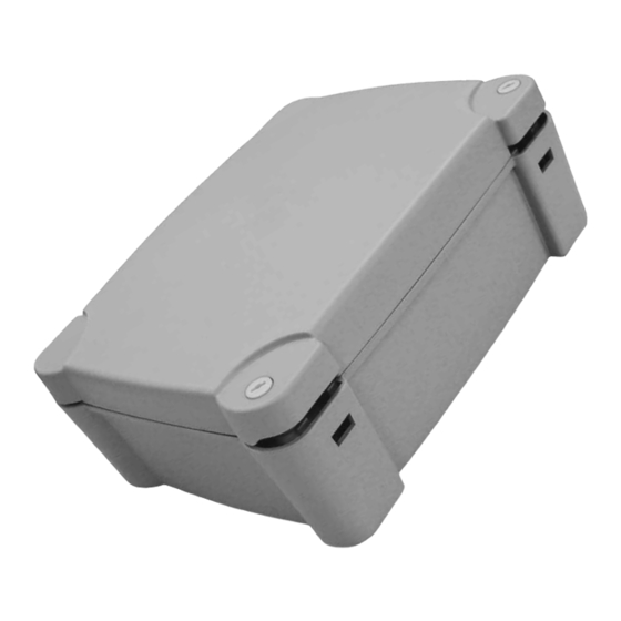
- Page 107 Istruzioni per il montaggio della centrale MINDY. Instructions for assembly of the MINDY control unit. Instructions pour le montage de l’unité MINDY. Anweisungen für die Montage der Steuerzentrale MINDY. Instrucciones para el montaje de la central MINDY. Aanwijzingen voor montage van de besturingseenheid MINDY Inserire le due viti negli appositi fori superiori facendole scorrere sulla guida, come fig.
- Page 108 Shanghai Tel. +39.06.72.67.17.61 Tel. +33.(0)4.42.62.42.52 info@es.niceforyou.com Tel. +86.21.575.701.45/46 Fax +39.06.72.67.55.20 Fax +33.(0)4.42.62.42.50 Fax +86.21.575.701.44 inforoma@niceforyou.com info@cn.niceforyou.com www.niceforyou.com Nice Gate is the doors and gate automation division of Nice Nice Screen is the rolling shutters and awnings automation division of Nice...
Need help?
Do you have a question about the Mindy A824 and is the answer not in the manual?
Questions and answers