Hafler trans-nova 9505 Installation And Operation Manual
Professional power amplifier
Hide thumbs
Also See for trans-nova 9505:
- Installation and operation manual (16 pages) ,
- Specifications (2 pages) ,
- Repairing instructions (5 pages)

Related Manuals for Hafler trans-nova 9505


Summary of Contents for Hafler trans-nova 9505
- Page 1 9505 Installation & Operation ® PROFESSIONAL POWER AMPLIFIER PROFESSIONAL POWER AMPL...
- Page 2 TO PREVENT FIRE OR SHOCK HAZARD DO NOT EXPOSE THIS EQUIPMENT TO RAIN OR MOISTURE. READ INSTRUCTIONS All the safety and operating instructions of your Hafler equipment should be read before power is applied to the equipment. RETAIN OWNER'S MANUAL These safety and operating instructions should be retained for future reference.
- Page 3 (48.26cm x 31.75cm x 13.34cm) *plus 1" (2.54cm) for handles Net Weight: 50 lbs. (22.68kg) P E C I F I C A T I O N S – ii – 16.94 19.00 Series 9505 True-balanced JFET input Power amplifier 12.05 1.19 ® 5.20...
-
Page 4: Table Of Contents
Cleaning and Maintenance ... 6 PC Board Layout ... 7 Schematic Diagram ... 8 Parts List ... 10 9505 Functional Block Diagram ... 12 TECHNICAL INFORMATION Theory and Operation of trans• nova ... 13 Circuit Implementation ... 13 Calibration ... 14 Common Mode Rejection ... -
Page 5: Introduction
This manual contains information on using the 9505 amplifier and is organized into three main sections. “Installation” covers the location and connection of the amplifier in the system. Like many precision components, careful attention to the initial setup can yield dividends in higher performance and trouble-free use. -
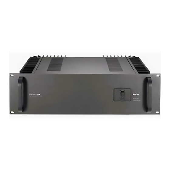
Page 6: Front/Rear Panel View
– 2 –... -
Page 7: Installation
Fan center approximately in line with edge of unit and starting of heatsink fins AC LINE The 9505 amplifier operates from a 120 volt, 60Hz AC power line. Connection is made by a 16 gauge, IEC Type 320, grounded line cord. For safety considerations only a properly grounded (earthed) receptacle should be used. -
Page 8: Input
UNBALANCED INPUT The unbalanced inputs use conventional RCA phone jacks. Set the BALANCED/UNBALANCED switch to the UNBALANCED position to use these jacks. BALANCED INPUT The input jacks located on the back of the amplifier are dual function connectors which accept 1/4" Phone (Tip Ring Sleeve) or XLR plugs. -
Page 9: Operation
When the amplifier is bridged the output is floating. Any speaker which requires a common ground from the amplifier output cannot be used in this application. Cuando el amplificador esté en modo puente (bridge), la salida del mismo es flotante (sin neutro). Cualquier parlante que necesite una tierra común de la salida del amplificador, no puede ser usado cuando el modo puente esté... -
Page 10: Input Switch
LOAD FAULT PROTECTION Because of the self-protecting properties and fault tolerance of the lateral MOSFETs used in the 9505, elaborate voltage and current limiting protection schemes are not necessary. To prevent damage to the amplifier from a fault in the loudspeaker load, the power supply B+ and B–... -
Page 11: Pc Board Layout
P C B O A R D A Y O U T – 7 –... -
Page 12: Schematic Diagram
301-399: Chassis/Power Supply 4. Left Channel Only Shown 5. Stereo/Mono Switch Shown in Stereo 6. Balanced/Unbalanced Switch Shown in Balanced Position 7. Chassis/Float Ground Switch Shown in Float Position Model 9505 CE Line Fuse 8A SLO-BLO (5x20mm) 230 VAC 50/60Hz I A G R A M –... - Page 13 – 9 –...
-
Page 14: Parts List
A R T S I S T DESIGNATOR VALUE ALL RESISTORS IN OHMS R1, R101 47.5k, 1/4W, 1% R2, R102 47.5k, 1/4W, 1% R3, R103 1k, 1/4W, 5% R4, R104 1k, 1/4W, 5% R5, R105 2.2M, 1/4W, 5% R6, R106 100, 1/4W, 5% R7, R107 22k, 1/4W, 5%... - Page 15 DESIGNATOR VALUE Q8, Q108 MMBT5087L Q10, Q110 MMBT5088L Q11, Q111 MMBT5087L Q12, Q112 MMBT5088L Q13, Q113 MMBT5087L Q14, Q114 MPS-A56 Q15, Q115 MPS-A56 Q16, Q116 MPS-A06 Q17, Q117 MPS-A06 Q45, Q145 2SK1058 Q46 Q146 2SK1058 Q47, Q147 2SK1058 Q48, Q148 2SK1058 Q49, Q149 2SJ162...
-
Page 16: 9505 Functional Block Diagram
9505 F UNCTIONAL LEFT INPUT (–) BALANCED/ UNBALANCED SWITCH RIGHT INPUT (–) STEREO/MONO LOCK IAGRAM (+) BUFFER (–) BUFFER (+) BUFFER (–) BUFFER SWITCH RIGHT CH. LEFT CH. HIGH VOLTAGE HIGH VOLTAGE LOW VOLTAGE POWER POWER POWER SUPPLY SUPPLY SUPPLY –... -
Page 17: Theory And Operation Of Trans• Nova
(voltage-to-current converter). The 9505 is the most sophisticated amplifier we have yet developed utilizing the basic trans• nova principle. And, although the measured specifications are very good, the numbers do not describe the realistic sound of the amplifiers. -
Page 18: Calibration
The final output stage utilizes lateral MOSFETs; four pairs are used for each channel in the 9505. These devices, unlike conventional bipolar transistors do not exhibit “thermal runaway.” Thermal runaway is a phenomenon whereby a transistor heats up as it draws more current, which causes it to get hotter, and conduct more current, and so on until the device self destructs. -
Page 19: Warranty
• How to obtain service or technical support Please call 1-800-669-9899 for Rockford/Hafler support. You must obtain an RA # (return authorization number) to return any products to Hafler. You are responsible for shipment of product to Hafler. - Page 20 LEA LAS INSTRUCCIONES Todas las instrucciones de seguidad y operación de su equipo Hafler, deben ser leídas antes de que el equipo sea conectado dléctricamente. CONSERVE EL MANUAL DEL PROPIETARIO Estas instrucciones de seguridad y operación, deben ser...
- Page 21 à éviter toute pénetration dans l'enceinte du matériel. 14. DÉGÂT NÉCESSITANT UNE RÉVISION Le matériel Hafler devrait être révisé par des personnes qualifées de service après-vente, lorsque: A. Les fiches ou la prise de courant ont été endommagé, ou: B.
- Page 22 Um die gefahr eines elektroschocks oder feuer zu vermeiden, setzen sie das gerät keinem regen oder extremer feuchtigkeitaus. INSTSRUKTIONEN LESEN Alle Sicherheits- und Operationshinweise Ihres Hafler Equip- ments sollten vor der Inbetriebnahme gelesen werden. BETRIEBSANLEITUNG AUFBEWAHREN Bewahren Sie die Bedienungsanleitung sorgfältig auf, damit Sie in dieser auch in Zukunft nachschlagen können.
- Page 23 Si deve prestar attenzione che oggetti e liquidi, come fluidi detergenti e bibite, non vengano versati all'interno dell'apparato. 14. RIPARAZIONI Gli apparati Hafler devono essere riparati da personale qualificato quando: A. Il cavo di alimentazione o la spina sono danneggiati B.
- Page 24 HAFLER PROFESSIONAL A DIVISION OF ROCKFORD CORPROATION 546 SOUTH ROCKFORD DRIVE TEMPE, ARIZONA 85281 U.S.A. IN U.S.A. (602) 967-3565 IN EUROPE, FAX (49) 8503-934014 IN JAPAN, FAX (81) 559-79-1265 MAN-0587-E 8/97...
Need help?
Do you have a question about the trans-nova 9505 and is the answer not in the manual?
Questions and answers