
Related Manuals for Hafler trans-nova P4000


Summary of Contents for Hafler trans-nova P4000
- Page 1 P4000 Installation & Operation ® PROFESSIONAL POWER AMPLIFIER PROFESSIONAL POWER AMPL...
- Page 2 TO PREVENT FIRE OR SHOCK HAZARD DO NOT EXPOSE THIS EQUIPMENT TO RAIN OR MOISTURE. READ INSTRUCTIONS All the safety and operating instructions of your Hafler equipment should be read before power is applied to the equipment. RETAIN OWNER'S MANUAL These safety and operating instructions should be retained for future reference.
- Page 3 E R F O R M A N C E P4000 Power Rating: FTC (20Hz-20kHz, 0.2% THD) 200 wpc into 8 275 wpc into 4 550 wpc into 8 (bridged mono) Signal-to-Noise Ratio: 100dB below rated output from 20Hz-20kHz “A” Weighted Frequency Response: 20Hz-20kHz, 0.1dB...
-
Page 4: Table Of Contents
Cleaning and Maintenance ... 7 TECHNICAL REFERENCE Field Service Considerations ... 8 Theory and Operation of trans• nova ... 8 P4000 Functional Block Diagram ... 9 Schematic Diagram ... 10 PC Board Layout ... 10 Parts List ... 13 Circuit Operation ... 15 Amplifier Module Replacement ... -
Page 5: Introduction
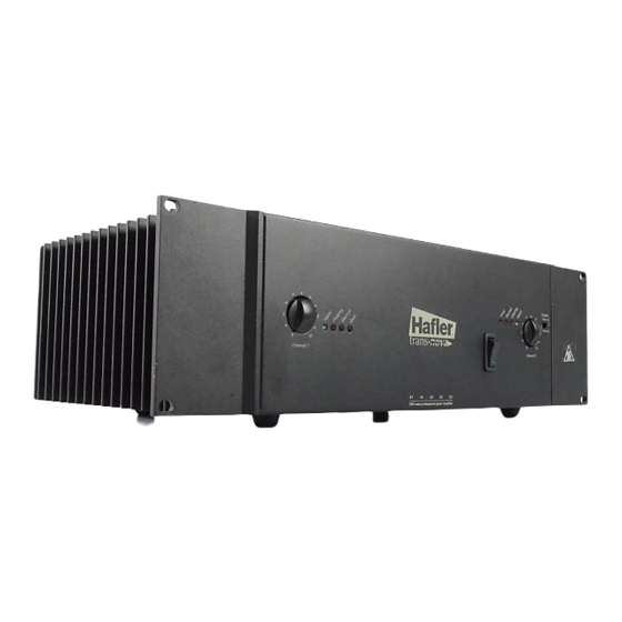
N T R O D U C T I O N The Hafler P4000 is a three rack height, two channel professional power amplifier suitable for use in any situation where a moderately powered compact amplifier is required. The P4000 is particularly attractive for use in monitoring situations. -
Page 6: Front & Rear Panel View
– 2 –... -
Page 7: Installation
Fan center approximately in line with edge of unit and starting of heatsink fins AC LINE The P4000 amplifier operates from a 120 volt, 60Hz AC power line. Connection is made by a 16 gauge, IEC Type 320, grounded line cord. For safety considerations only a properly grounded (earthed) receptacle should be used. -
Page 8: Input
Pin 2 = (+) Pin 3 = (–) Many popular mixers use unbalanced outputs and can be used with the Hafler amplifier. To minimize residual ground noise, we recommend using twisted pair cable or short cable lengths in this type of configuration. - Page 9 When the amplifier is bridged the output is floating. Any speaker which requires a common ground from the amplifier output cannot be used in this application. Cuando el amplificador esté en modo puente (bridge), la salida del mismo es flotante (sin neutro). Cualquier parlante que necesite una tierra común de la salida del amplificador, no puede ser usado cuando el modo puente esté...
-
Page 10: Operation
P E R A T I O N POWER SWITCH The POWER switch is located on the front panel of the amplifier. An internal lamp indicates when it is turned on. Standard practice is to turn the amplifier on last and off first when switching components to prevent sending damaging transients to the speakers. -
Page 11: Ground Switch
GROUND SWITCH Ground loops are characterized by a hum or buzz through the speakers and are caused by a voltage potential difference between two points in a ground circuit. Ground loops are aggravated when multiple paths exist for a given circuit. Mounting components in a rack with metal rails may introduce ground loops between associated equipment, because the rails can establish an additional ground path. -
Page 12: Technical Reference
The disadvantage of the Class A driver stage is the limited current headroom available. A conventional Class A transconductance stage has a 2:1 or 6dB limit on peak to quiescent current. The number of MOSFETs used in the P4000 imposes a significant capacitive load on the driver stage, enough of a load to strain the ability of the driver to deliver the required current at the higher audio frequencies. -
Page 13: P4000 Functional Block Diagram
P4000 F UNCTIONAL +17V Positive Input Positive Buffer Buffer Level Adjust Balanced Signal R24 A, B DC Offset Integrator U2B, R11, C332 Negative Input Buffer Protection Switch, Soft Start Delay –17V LOCK IAGRAM Current Mirror Q104, Q105 DIAMOND CMRR Adjust... -
Page 14: Schematic Diagram
C H E M A T I C I A G R A M NOTES: Unless specified otherwise 1. All resistors in ohms. 2. All capacitors in microfarads. 3. Channel 1 only shown. – 10 –... - Page 15 Model P4000CE 6.3A SLO-BLO SLO-BLO LINE 230 VAC 120 VAC 50/60Hz 60 HZ NEUTRAL GROUND GRN/YLW – 11 – AC CAPACITOR RECTIFIER WHT/ORG PRI. A BLK/WHT BLK/WHT WHT/BLU PRI. B +RED BRIDGE -BLU...
- Page 16 P C B O A R D A Y O U T PC-1487-C – 12 –...
-
Page 17: Parts List
A R T S I S T DESIGNATOR VALUE ALL RESISTORS IN OHMS 56.2k, 1/4W, 1% 1k, 1/4W, 1% 47k, 1/4W, 5% 47k, 1/4W, 5% 4.7k, 1/4W, 5% 4.7, 1/4W, 5% 909, 1/4W, 1% 200, Trim Pot 1k, 1/4W, 1% 28k, 1/4W, 1% 2.2M, 1/4W, 5% 28k, 1/4W, 1%... - Page 18 P Channel MOSFET LED Red LED Red LED Red LED Green MMBD914L Diode MMBD914L Diode MMBD914L Diode MMBD914L Diode CR10 Bridge Rectifier, 1.5 Amp CR11 BAV99L Dual Diode CR12 BAV99L Dual Diode CR13 MMBD914L Diode CR14 BAV99L Dual Diode CR15...
-
Page 19: Circuit Operation
The transistor Q1 is configured to operate as a switch which controls the current source, Q103, of the input differential amp, Q6 and Q7. When Q1 is off the emitter voltage is low turning off Q103. Timing of the Soft Start function is controlled by the charging time of C29 through R13. - Page 20 Output Short Protection Clip Detector Drive Signal Output Signal The Short detector monitors the Drive Signal and Output Signal levels and shuts down that channel when a shorted output condition is detected. Recovering for the Short protection requires turning the amplifier off to reset it. The comparator U4B monitors the Drive Signal and goes low when the drive level is sufficient to clip the output stage.
- Page 21 Thermal Protection Temp Comparator TS1, R25 The thermal protection is activated, and shuts down audio operation, when the amplifier heatsink reaches an excessively high temperature. The voltage divider R22 and R23 establishes the reference voltage on pin 5 of U5B. The control voltage on pin 4 is established by the voltage divider TS1 and R25.
-
Page 22: Amplifier Module Replacement
AMPLIFIER MODULE REPLACEMENT The amplifier modules have been designed to eliminate the need for a special workplace if a field exchange becomes necessary. All wire connections are made with quick connect terminals so soldering is not necessary. The following tools are needed to disassemble the amplifier: Allen wrench, 9/64 Allen wrench, 7/64 Phillips screwdriver, #1 tip... -
Page 23: Warranty
• How to obtain service or technical support Please call 1-800-669-9899 for Rockford/Hafler support. You must obtain an RA # (return authorization number) to return any products to Hafler. You are responsible for shipment of product to Hafler. - Page 24 LEA LAS INSTRUCCIONES Todas las instrucciones de seguidad y operación de su equipo Hafler, deben ser leídas antes de que el equipo sea conectado dléctricamente. CONSERVE EL MANUAL DEL PROPIETARIO Estas instrucciones de seguridad y operación, deben ser...
- Page 25 à éviter toute pénetration dans l'enceinte du matériel. 14. DÉGÂT NÉCESSITANT UNE RÉVISION Le matériel Hafler devrait être révisé par des personnes qualifées de service après-vente, lorsque: A. Les fiches ou la prise de courant ont été endommagé, ou: B.
- Page 26 Um die gefahr eines elektroschocks oder feuer zu vermeiden, setzen sie das gerät keinem regen oder extremer feuchtigkeitaus. INSTSRUKTIONEN LESEN Alle Sicherheits- und Operationshinweise Ihres Hafler Equip- ments sollten vor der Inbetriebnahme gelesen werden. BETRIEBSANLEITUNG AUFBEWAHREN Bewahren Sie die Bedienungsanleitung sorgfältig auf, damit Sie in dieser auch in Zukunft nachschlagen können.
- Page 27 Si deve prestar attenzione che oggetti e liquidi, come fluidi detergenti e bibite, non vengano versati all'interno dell'apparato. 14. RIPARAZIONI Gli apparati Hafler devono essere riparati da personale qualificato quando: A. Il cavo di alimentazione o la spina sono danneggiati B.
- Page 28 ® HAFLER PROFESSIONAL A DIVISION OF ROCKFORD CORPORATION 546 SOUTH ROCKFORD DRIVE TEMPE, ARIZONA 85281 U.S.A. IN U.S.A. (602) 967-3565 IN CANADA, (604) 942-1001 IN EUROPE, FAX 8503-9340-14 IN JAPAN, FAX (81) 559-79-01265 MAN-1498-B 6/97...
Need help?
Do you have a question about the trans-nova P4000 and is the answer not in the manual?
Questions and answers