Table of Contents
Advertisement
Advertisement
Table of Contents

Related Manuals for Hafler 0915P


Summary of Contents for Hafler 0915P
- Page 1 Haflee H O M E A U D I O C O M P O N E N T S Series 915 Preamp Series 0915...
- Page 2 SHOCK HAZARD, DO NOT EXPOSE THIS EQUIPMENT TO RAIN OR MOISTURE. READ INSTRUCTIONS All the safety and operating instructions of your Hafler equipment should be read before power is applied to the equipment. RETAIN OWNERS MANUAL These safety and operating instructions should be retained for future reference.
- Page 3 Care should be taken so that objects and/or liquids, such as cleaning fluids or beverages, are not spilled into the enclosure of the equipment. DAMAGE REQUIRING SERVICE Hafler equipment should be serviced by qualified service personnel when: The power supply cord or plug has been damaged, or Objects have fallen, or liquid has been spilled into the equipment, or...
-
Page 4: Table Of Contents
TABLE OF CONTENTS PERFORMANCE SPECIFICATIONS ... General Information ... INSTALLATION Rackmounting ... Ventilation/Placement ... Line Voltage ... OPERATION/CONNECTIONS Power Cord Connection ... Initial Power-Up/Muting System ... Convenience Outlets ... Line Level Inputs ... Phono Section ... Front Panel View Diagram ... Rear Panel View Diagram ... -
Page 5: Performance Specifications
PERFORMANCE SPECIFICATIONS All specifications are for 20 Hz - 20 kHz unless specified otherwise. PHONO SECTION FREQUENCY RESPONSE: +/-0.1 dB (Measured At MAXIMUM OUTPUT: 5 volts RMS REC OUT) TOTAL HARMONIC DISTORTION AND NOISE: Moving Magnet: .002% Moving Coil: .009% SENSITIVITY (For 0.5 volts RMS at REC OUT, @ 1 kHz): Moving Magnet: 6.0 mV RMS Moving Coil: 600 uV RMS... -
Page 6: Installation Rackmounting
GENERAL INPUTS: Tuner, Video, CD, Phono/Aux INFORMATION OUTPUTS: Out 1, Out 2, Record Out, Headphone CONTROLS: input Selector, Volume, Tape Monitor , Tone Control In, Balance, Bass, Treble, Output Off, Power, Phono MM/MC INDICATORS: Mute/Standby, Power CONVENIENCE OUTLETS: 1 Unswitched, (Convenience Outlets are not included on 200-240 VAC units) PHYSICAL 17”... -
Page 7: Convenience Outlets
For units wired for 100-120 VAC, the Power Switch controls the Switched Convenience Outlets only. As soon as the 915 is plugged into the AC line, power is applied to the circuitry (regardless of the position of the front panel Power Switch). Therefore, all connections should be performed with the unit unplugged. -
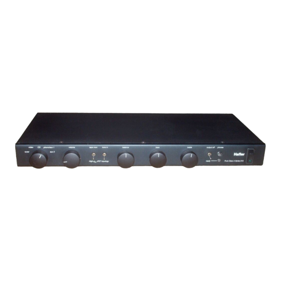
Page 8: Front Panel View Diagram
INPUT SELECTOR VOLUME CONTROL RACKMOUNT HOLES TAPE MONITOR SWITCH (19” VERSION ONLY) UP TO MONITOR TAPE INPUT BALANCE CONTROL BASS CONTROL TONE IN SWITCH UP TO ACTIVATE BASS & TREBLE 915 PREAMPLIFIER FRONT PANEL VIEW *lOO-120 VAC UNITS ONLY. 200-240 VAC UNITS ARE WITHOUT CONVENIENCE OUTLETS: POWER SWITCH CONTROLS PREAMPLIFIER POWER. -
Page 10: Tape Input/Record Output
TAPE INPUT/ The 915 incorporates one monitoring loop for use with tape decks, or other input/output signal RECORD OUTPUT processors. The Ret Out jack feeds a signal to a tape recorder’s input. The signal present at this output is the same as indicated by the Selector Switch. This output may alternately be used to feed the input of a signal processing device, such as an equalizer. -
Page 11: Out 1, Out 2, And Output Switch
OUT 1, OUT 2 Activating this switch (UP position) turns off both Out 1 and Out 2. It does not affect the headphone AND OUTPUT OFF output. This control is useful for turning off the signal to the power amplifier(s) during headphone SWITCH listening, or for general system muting purposes. -
Page 12: Jfet Buffer And Record Output Driver
The output of the Selector System is followed by a very high input-impedance JFET buffer pair JFET BUFFER AND to establish negligible CMOS switch loading (for low distortion) and to provide a low-impedance RECORD OUTPUT source for the Record Output and the Volume and Balance controls. DRIVER The Tape Monitor Switch drives a relay to break the line input path to insert tape input signals. -
Page 13: Headphone Amplifier
To convert this input for use with a turntable, purchase the 915 Phono Option Accessory from your Hafler Dealer. Review the installation instructions before attempting this procedure. If any doubts exist about one’s ability to install the Phono Option, it is advisable that the procedure be conducted by a qualified technician. -
Page 15: Installing Cartridge Loads
INSTALLING Optional cartridge loading is a “fine tuning” matter. Many cartridges are not sensitive to loading CARTRIDGE LOADS and work well without it. Only every cartridge is different. And only the user can say for sure whether or not it produces meaningful sonic improvement. -
Page 17: General Troubleshooting Hints
Place the preamplifier on a soft, protective surface. Remove the eight allen head screws (four on each side), and six phillips bottom covers. Remove covers. Referring to the diagram “Main Printed Circuit Board Component Layout”, locate the three wire jumper locations labelled control the series/parallel connections of the power transformer’s primary. -
Page 18: Ground Loops
Ground loops are characterized by a low level hum or buzz in the system. Loops are caused by GROUND LOOPS a voltage potential difference between two points in a ground circuit, and aggravated when multiple paths for a given circuit exist. Noise-free audio performance is dependent upon all grounds being at the same potential, with a single path for each ground connection. -
Page 20: Main Circuit Board
PARTS LIST PARTS LIST DESIGNATORS l-99: FOR COMMON AND RIGHT CHANNEL PARTS 100-199: FOR LEFT CHANNEL DESIGNATOR VALUE ALL RESISTORS 1/4 WATT, 1% METAL FILM R1, R101 2.15K R2, R102 100K 100K 100K R6, R106 R7, R107 R8, R106 R9, R109 33.2 R10, R110 33.2... -
Page 22: Main Board Circuit Schematic Diagram
rJoba’- ----- +--- ’ A----- P H O N O P W E R PWNOOPllONJUMPERS A&B=100-12OVW: c - 2 0 0 - 2 4 0 VAE: +15V - 1 5 V +15V 1 N5226B lN4145 +15V- L C H... -
Page 23: Phono Board Parts List
BOARD CIRCUIT SCHEMATIC ENANCE MUTE RUAY UNLESS SPECIFIED OTHERWISE 1. RIGHT CHANNEL ONLY SHOWN 2. COMPONENT DESIGNATORS 1-99 F O R COMMON AND RIGHT CHANNEL PARTS. 100-199 FUR L E F T CHANNEL 5. ML RESISTORS IN OHMS, CAPACITORS IN M I C R O F A R A D S 4.TCNE5WllCHSHWNINBYPASSPO5RlCN 5. - Page 24 PARTS LIST PARTS LIST - PHONO BOARD DESIGNATORS 1 - 99: FOR RIGHT CHANNEL PARTS 100-l 99: FOR LEFT CHANNEL DESIGNATOR VALUE PART NUMBER All Resistors 1/4 Watt, 1% Metal Film R1, R101 R2, R102 33.2 L o w Noise R3, R103 33.2 L o w Noise R4, R104...
-
Page 25: Phono Board Component Layout Diagram
RlO RlO R 2 -c=l- -c=l- "R1B05 "R1B05 c5 c5 jRSo jRSo Rl9 Rl9 J3 J3 PHONO BOARD COMPONENT LAYOUT DIAGRAM -fxb R 1 0 3 -fxb 0 1 0 4 0 1 0 4 R l 1 8 "OS R l 1 8 "OS ii:: ii:: R l 1 3... -
Page 26: Phono Board Circuit Schematic Diagram
PHONO INPUT L CH IMC/MM SWrrCH PHONO POWER 1. RIGHT CHANNEL ONLY SHOWN. 2. COMPONENT DESIGNATORS 1-99 FOR RIGHT CHANNEL PARTS. 1 W-199 FOR LEFT CHANNEL. 3. ALL RESISTORS IN OHMS, CAPACITORS IN MICROFARADS. 4. MC/MM SWITCH SHOWN IN MOVING MAGNET POSITION. PHONO BOARD CIRCUIT SCHEMATIC DIAGRAM D,‘) I.,#. -
Page 27: Service Policy And Limited Warranty
The Hafler 915 Preamplifier is warranted to the original owner (non-transferrable) for seven years from the date of purchase, including parts, labor, and return shipping costs within the Continental United States.
Need help?
Do you have a question about the 0915P and is the answer not in the manual?
Questions and answers