
Related Manuals for Hafler 9303


Summary of Contents for Hafler 9303
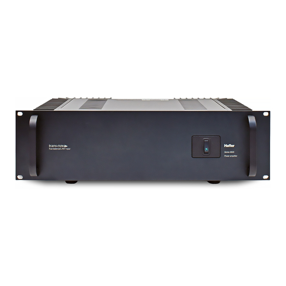
- Page 1 9303 / 9505 Installation & Operation ® PROFESSIONAL POWER AMPLIFIER PROFESSIONAL POWER AMPL...
- Page 2 SHOCK HAZARD, DO NOT EXPOSE THIS EQUIPMENT TO RAIN OR MOISTURE. READ INSTRUCTIONS All the safety and operating instructions of your Hafler equipment should be read before power is applied to the equipment. RETAIN OWNER'S MANUAL These safety and operating instructions should be retained for future reference.
-
Page 3: Specifications
E R F O R M A N C E 9303/9505 Full Power Bandwidth: 0.15Hz to 300kHz Signal-to-Noise: >100dB “A” Weighted Slew Rate: 150 V/ s CMRR: 75dB at 1kHz Gain: +29dB max. 9303 Power Rating: 150 wpc @8 , 225 wpc @ 4 , 450 Watts mono @ 8 Distortion: 0.07% THD 20-20Hz, Typically 0.005% THD 1kHz, at rated power into 8... -
Page 4: Table Of Contents
Cleaning and Maintenance ... 3 Schematic Diagram ... 4 PC Board Layout ... 6 Parts List ... 7 9303/9505 Functional Block Diagram ... 8 TECHNICAL INFORMATION Theory and Operation of trans• nova ... 9 Circuit Implementation ... 9 Calibration ... 10 Common Mode Rejection ... -
Page 5: Introduction
AC LINE The 9303 and 9505 operate from a 120 volt, 60Hz AC power line. Connection is made by an IEC Type 320, grounded line cord. For safety considerations only a properly grounded (earthed) receptacle should be used. -
Page 6: Input
INPUT The 9303 and 9505 have input jacks for both balanced and unbalanced input signals. The unbalanced inputs use conventional RCA phono jacks. When using the RCA inputs, the rear panel BALANCED/UNBALANCED switch must be set to the UNBALANCED position. The balanced input jacks are dual function connectors which accept 1/4"... -
Page 7: Operation
LOAD FAULT PROTECTION Because of the self-protecting properties and fault tolerance of the lateral MOSFETs used in the 9303 and 9505, elaborate voltage and current limiting protection schemes are not necessary. To prevent damage to the amplifier from a fault in the loudspeaker load, the power supply B+ and B– rails are fused. Check these fuses if the sound is garbled or there is no output. -
Page 8: Schematic Diagram
C H E M A T I C NOTES: Unless specified otherwise 1. All resistors in ohms 2. All capacitors in microfarads 3. Component Designators: 1-99: Left Channel 101-199: Right Channel 201-299: Common Parts 301-399: Chassis/Power Supply 4. Left Channel Only Shown 5. - Page 9 – 5 –...
-
Page 10: Pc Board Layout
P C B O A R D A Y O U T – 6 –... -
Page 11: Parts List
A R T S I S T DESIGNATOR VALUE ALL RESISTORS IN OHMS R1, R101 47.5k, 1/4W, 1% R2, R102 47.5k, 1/4W, 1% R3, R103 1k, 1/4W, 5% R4, R104 1k, 1/4W, 5% R5, R105 2.2M, 1/4W, 5% R6, R106 100, 1/4W, 5% R7, R107 22k, 1/4W, 5%... -
Page 12: 9303/9505 Functional Block Diagram
Q202 MMBT5088L Q203 MMBT5088L F1, F101 AGC 10A Fuse F2, F102 AGC 10A Fuse F201 15A Slo/Blo F203, F204 2.5A Fast Mini 9303 / 9505 F LEFT INPUT (–) BALANCED/ UNBALANCED SWITCH RIGHT INPUT (–) STEREO/MONO SWITCH PART # SS-0115... -
Page 13: Theory And Operation Of Trans• Nova
Many “balanced” amplifiers are merely conventional unbalanced designs with a Balanced-to-Unbalanced converter (usually IC op-amp based) preceding the power amplifier. The 9303 and 9505, however, are true differential input power amplifiers. Each (+) and (–) input port has been buffered to allow direct signal access to the differential amplifier, without conversion to unbalanced form. -
Page 14: Calibration
High voltage power supply capacitance is 20,000 F per rail for each channel for the 9505 and 5,000 for the 9303. The third transformer secondary feeds a regulated supply for the input stage and driver circuitry. -
Page 15: Warranty
I M I T E D A R R A N T Y If you encounter any difficulty or have any question concerning your 9303 and 9505 Amplifier, please call our Technical Support Department weekdays, 8:00 a.m. to 3:30 p.m., Mountain Standard Time, at 800-795-2385. - Page 16 HAFLER PROFESSIONAL A DIVISION OF ROCKFORD CORPROATION 546 SOUTH ROCKFORD DRIVE TEMPE, ARIZONA 85281 U.S.A. IN U.S.A. (602) 967-3565 IN EUROPE, FAX (49) 4207-801250 IN JAPAN, FAX (81) 559-79-01265 MAN-0587-D 4/95...
Need help?
Do you have a question about the 9303 and is the answer not in the manual?
Questions and answers