
Related Manuals for Hafler trans-nova P1000


Summary of Contents for Hafler trans-nova P1000
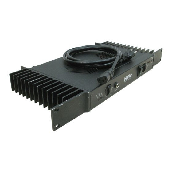
- Page 1 P1000 Installation & Operation ® PROFESSIONAL POWER AMPLIFIER PROFESSIONAL POWER AMPL...
-
Page 2: Declaration Of Conformity
Declaration of Conformity Application of Council Directive: 73 / 23 / EEC (Low Voltage Directive) Standard(s) to which Conformity is Declared: EN55103-1 Manufacturer’s Name: Hafler Manufacturer’s Address: 546 South Rockford Drive, Tempe, Arizona 85281 Importer’s Name: Importer’s Address: Type of Equipment: 2-channel Audio Power Amplifier/Speaker Model No.: P1000CE... - Page 3 152W/1.3A @ 120VAC (1/8 power – 8 ) (both channels driven) 260W/2.2A @ 120VAC (max. power – 8 ) Controls & Switches: Front Panel: Power switch, Normal/Bridged mono switch, level controls Rear Panel: Chassis/Float ground switch, Balanced/Unbalanced switch 115V/230V Power line selector...
- Page 4 TO PREVENT FIRE OR SHOCK HAZARD DO NOT EXPOSE THIS EQUIPMENT TO RAIN OR MOISTURE. READ INSTRUCTIONS All the safety and operating instructions of your Hafler equipment should be read before power is applied to the equipment. RETAIN OWNER'S MANUAL These safety and operating instructions should be retained for future reference.
- Page 5 LEA LAS INSTRUCCIONES Todas las instrucciones de seguidad y operación de su equipo Hafler, deben ser leídas antes de que el equipo sea conectado dléctricamente. CONSERVE EL MANUAL DEL PROPIETARIO Estas instrucciones de seguridad y operación, deben ser conservadas...
- Page 6 à éviter toute pénetration dans l'enceinte du matériel. 14. DÉGÂT NÉCESSITANT UNE RÉVISION Le matériel Hafler devrait être révisé par des personnes qualifées de service après-vente, lorsque: A. Les fiches ou la prise de courant ont été endommagé, ou: B.
- Page 7 Um die gefahr eines elektroschocks oder feuer zu vermeiden, setzen sie das gerät keinem regen oder extremer feuchtigkeitaus. INSTRUKTIONEN LESEN Alle Sicherheits- und Operationshinweise Ihres Hafler Equipments sollten vor der Inbetriebnahme gelesen werden. BETRIEBSANLEITUNG AUFBEWAHREN Bewahren Sie die Bedienungsanleitung sorgfältig auf, damit Sie in dieser auch in Zukunft nachschlagen können.
- Page 8 Si deve prestar attenzione che oggetti e liquidi, come fluidi detergenti e bibite, non vengano versati all'interno dell'apparato. 14. RIPARAZIONI Gli apparati Hafler devono essere riparati da personale qualificato quando: A. Il cavo di alimentazione o la spina sono danneggiati B.
-
Page 9: Table Of Contents
Field Service Considerations ... 9 Theory and Operation of trans• ana ... 9 PC Board Layout ... 10 Parts List ... 11 P1000 Functional Block Diagram ... 13 Circuit Operation ... 14 Amplifier Module Replacement ... 17 WARRANTY ... 18... -
Page 10: Introduction
N T R O D U C T I O N The Hafler P1000 is a single rack height, two channel professional power amplifier suitable for use in any situation where a moderately powered compact amplifier is required. The P1000 is particularly attractive for use in broadcast monitoring situations. -
Page 11: Front & Rear Panel View
– 2 –... -
Page 12: Installation
AC LINE The P1000 is capable of operation from either a 115 VAC/60Hz or a 230 VAC/50-60Hz power line. The power line selector switch is located on the rear panel. Check that the switch is set in the correct position before putting the amplifier into service. -
Page 13: Balanced Input
Pin 2 = (+) Pin 3 = (–) Many popular mixers use unbalanced outputs and can be used with the Hafler amplifier. To minimize residual ground noise, we recommend using twisted pair cable or short cable lengths in this type of configuration. -
Page 14: Operation
The input sensitivity, for each channel, can be adjusted individually using the level controls on the front panel. The level controls on the P1000 are configured to allow each channel to be fully attenuated and are marked from 0 (minimum output) to 10 (full output). -
Page 15: Nomad Safe Area Protection
This multiplication method has numerous problems, including temperature sensitivity, nonlinearity and complexity. The NOMAD circuit, used in the P1000, avoids these problems by deriving the device dissipation by a different method. Sensing circuits measure the device voltage and current. NOMAD determines the allowed current after an established duration. -
Page 16: Schematic Diagram
C H E M A T I C I A G R A M – 7 –... - Page 17 Amplifier Channel – 8 –...
-
Page 18: Field Service Considerations
FIELD SERVICE CONSIDERATIONS A primary focus during the design and development of the P1000 was to ensure the dependability of the amplifiers. The use of MOSFET output transistors and the low voltage trans• ana input stage combined with careful component selection for the circuit assembly made the reliability goals achievable. -
Page 19: Pc Board Layout
MUTE2 R56 C9 C M R R PC-1130-C ROCKFORD CORP ROCKFORD/HAFLER PC-1179-E LINE4 C101 J101 ROCKFORD/HAFLER ARTWORK COMPONENT SIDE R102 B I A S M.ALBERS PC-1130-C CHASS1 J100 115V 230V PC-1179-E P1000 Back Panel – 10 – X4 X3 LINE3... -
Page 20: Parts List
A R T S I S T DESIGNATOR VALUE ALL RESISTORS IN OHMS 33, 1/10W 1k, 1/4W, 1% 47k, 1/4W, 5% 47k, 1/4W, 5% 1k, 1/4W, 1% 4.7, 1/4W 909, 1/4W 200, Trim Pot 1k, 1/4W, 1% 4.7, 1/4W 300k, 1/4W, 5% 10k, 1/4W 470k, 1/4W, 5% 28k, 1/4W... - Page 21 DESIGNATOR VALUE C101 0.01 F, 1kV C119 0.1 F, 100V, Mylar C120 0.1 F, 100V, Mylar MMBT3904L, NPN LM-317 + Regulator LM-337 – Regulator MMBT5088L, NPN MMBT5088L, NPN MMBT3904L, NPN MMBT3906L, PNP MMBT3904L, NPN MMBT3906L, PNP MMBT3906L, PNP MMBT3906L, PNP MMBT3904L, NPN MMBT3904L, NPN IRF9540, P Channel MOSFET...
-
Page 22: P1000 Functional Block Diagram
P1000 F UNCTIONAL Positive Input DC Offset Buffer Integrator U2B, C22, C21, Level Balanced Input Buffer Control Signal R24A, B Negative Input Buffer LOCK IAGRAM Current Mirror Q7, Q9 CMRR Differential Amp Adjust Q4, Q5 Current Protection Switch Source Soft Start Delay Q1, C29 –... -
Page 23: Circuit Operation
The transistor Q1 is configured to operate as a switch which controls the constant current source, Q6, of the input differential amp, Q4 and Q5. When Q1 is off the emitter voltage is low turning off Q6. Timing of the Soft Start function is controlled by the charging time of C29 through R13. - Page 24 NOMAD (NOn-Multiplying Advance Decision) Stage Current R67 (R68) Gate Voltage Clamp Reference Voltage Dissipation Threshold Q17 (Q16) Q11 (Q13) Sense Q10 (Q12) Stage Voltage R43 (R54) Maximum power delivery, within the output MOSFET ratings for power, voltage and current, is ensured by our NOMAD (NOn-Multiplying Advance Decision, patent pending) circuit.
- Page 25 Thermal Protection Temp Comparator TS1, R25 The thermal protection is activated, and shuts down audio operation, when the amplifier heatsink reaches an excessively high temperature. The voltage divider R22 and R23 establishes the reference voltage on pin 5 of U5B. The control voltage, on pin 4 is established by the voltage divider TS1 and R25.
-
Page 26: Amplifier Module Replacement
AMPLIFIER MODULE REPLACEMENT The amplifier modules have been designed to eliminate the need for a special workplace if a field exchange becomes necessary. All wire connections are made with quick connect terminals so soldering is not necessary. The following tools are needed to disassemble the amplifier: Allen wrench, 9/64 Phillips screwdriver, #1 tip Thin nose pliers... -
Page 27: Warranty
• How to obtain service or technical support Please call 1-800-669-9899 for Rockford/Hafler support. You must obtain an RA # (return authorization number) to return any products to Hafler. You are responsible for shipment of product to Hafler. - Page 28 ® HAFLER PROFESSIONAL A DIVISION OF ROCKFORD CORPORATION 546 SOUTH ROCKFORD DRIVE TEMPE, ARIZONA 85281 U.S.A. IN U.S.A. (480) 967-3565 IN CANADA, (604) 942-1001 IN EUROPE, FAX (49) 4207-801250 IN JAPAN, FAX (81) 559-79-01265 www.hafler.com 11/99 E.W.R. MAN-1482-B...
Need help?
Do you have a question about the trans-nova P1000 and is the answer not in the manual?
Questions and answers