Table of Contents
Advertisement
Advertisement
Table of Contents

Related Manuals for Metso NORDBERG LT105


Summary of Contents for Metso NORDBERG LT105
- Page 1 NORDBERG LT105/LT105S INSTRUCTION MANUAL 140561-B https://tractormanualz.com/...
- Page 2 Nordberg LT105/105S CHAPTER This instruction manual is valid for diesel engine Nordberg LT105/105S is a portable jaw crusher driven Nordberg LT105/105S manufactured by unit, which is intented to be used in recycling Metso Minerals. crushing applications in crushing plants. Because of the continuous development of the...
- Page 3 PREFACE CHAPTER This instruction manual is intended to assist owners This instruction manual must be read and used by and users of Nordberg products in the proper use of each person who works with the equipment, the equipment. typically: It includes important references to safe, proper and –...
- Page 4 Chapter 2 Security SAFETY 2.1 WARNING SYMBOLS ............2.2 PERSONNEL SAFETY .
-
Page 5: Warning Symbols
SAFETY CHAPTER 2.1 WARNING SYMBOLS are presented as a helpful guide to construction equipment personnel and shows some of the daily The following symbols for particularly important work problems which they may encounter. instructions are being used in the instruction manual: It is the responsibility of the operator to know what specific requirements, precautions and work area... - Page 6 CHAPTER 2 - SAFETY DO YOU KNOW YOUR EMPLOYER'S Be a good housekeeper . . . keep the floor clean, SAFETY PROGRAM? free of oil, grease, rags, cables, chains, buckets, rocks and other hazards. Keep loose parts in a tool Company safety records show that the greatest box.
-
Page 7: Operation
CHAPTER 2 - SAFETY 4. CHECK every drain cock, valve and fitting 2.5 REPORT A DEFECTIVE MACHINE to sure it is in place and secure Inspect your machine daily . . . check for loose, 5. Loss of pressure from low fluid levels may worn or damaged parts. - Page 8 CHAPTER 2 - SAFETY on the Crusher. electrical equipment, are dangerous. 2. 2Provide each maintenance man with his 2. DO NOT let material lay and build up on or own personal padlock and ONE key. around the Crusher. 3. 3STORE dangerous fluids in a suitable place 2.11 CLOTHING - SAFE PRACTICE - away from unauthorized personnel.
- Page 9 CHAPTER 2 - SAFETY 5. DO NOT smoke while using cleaning USE QUALITY PARTS solvents. A replacement part for any item should always be 6. DO NOT let greasy, oily rags accumulate in of comparable SIZE, TYPE AND QUALITY - as poorly ventilated area.
- Page 10 Chapter 3 Main components MAIN COMPONENTS 3.1 MAIN ASSEMBLY ............3.2 DIESEL ENGINE .
-
Page 11: Main Components
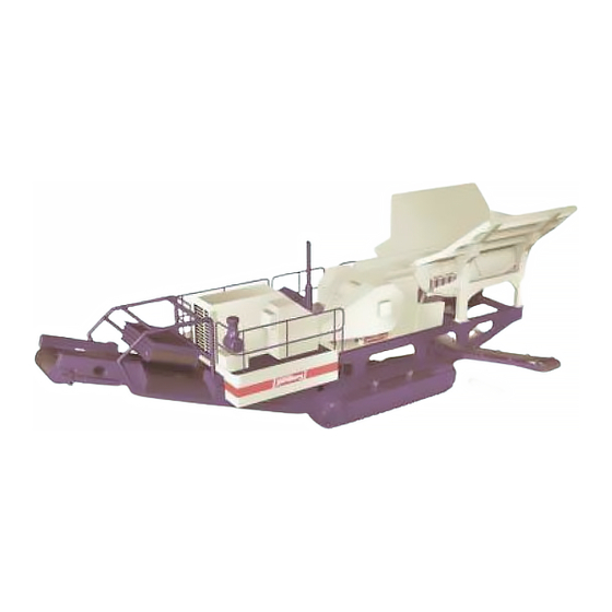
MAIN COMPONENTS CHAPTER 3.1 MAIN ASSEMBLY 1. Diesel engine 2. Tracks 3. Crusher 4. Feeder 5. Main conveyor 6. Side conveyor (optional) 7. Magnetic separator (optional) Figure 3-1 Main assembly 02/02 3-38-B NORDBERG LT105/105S INSTRUCTION MANUAL https://tractormanualz.com/... - Page 12 3.8 MAGNETIC SEPARATOR (OPTIONAL) The optional magnetic separator is installed above the main conveyor. It separates magnetic objects from the crushed material and transfers those to a separate pile beside the machine. NORDBERG LT105/105S INSTRUCTION MANUAL 3-38-B 02/02 https://tractormanualz.com/...
- Page 13 15. Engine oil drainage 6. Left track 16. Hydraulic outlet (PTO) 7. Right track 17. Hydraulic oil drainage 8. Feeder 9. Side conveyor / hand valves 10. Side conveyor turning, up/down Figure 3-9 Hydraulic valve location 02/02 3-38-B NORDBERG LT105/105S INSTRUCTION MANUAL https://tractormanualz.com/...
- Page 14 2. Adjustment wedge movement 3. Return rod pressurizing 1. Left side wall lifting and lowering 4. Return rod pressure sensor 2. Rear wall lifting and lowering 3. Right side wall lifting and lowering NORDBERG LT105/105S INSTRUCTION MANUAL 3-38-B 02/02 https://tractormanualz.com/...
-
Page 15: Engine Module
7. Coolant expansion tank c) Crusher drive pump pressure (when crusher 8. Crusher circuit filter running to normal direction) 9. Hydraulic pressure filter 2. Engine primary fuel filter and water separator 3. Dipstick 02/02 3-38-B NORDBERG LT105/105S INSTRUCTION MANUAL https://tractormanualz.com/... - Page 16 Figure 3-12 b) Engine module 1. Air cleaner 2. Air precleaner 3. Fuel filter, secondary 6. Hydraulic pressure filter 4. Mechanical fuel transfer pump 7. Coolant expansion tank 5. Engine electronics 8. Batteries 9. Crusher circuit filter NORDBERG LT105/105S INSTRUCTION MANUAL 3-38-B 02/02 https://tractormanualz.com/...
-
Page 17: Hydraulic Tank
CHAPTER 3 - MAIN COMPONENTS 3.13 HYDRAULIC TANK 1. Hydraulic return filter 2. Breather 3. Hydraulic oil sight glass 02/02 3-38-B NORDBERG LT105/105S INSTRUCTION MANUAL https://tractormanualz.com/... - Page 18 Chapter 4 Control panels CONTROL PANELS 4.1 OPERATING PANEL SWITCHES/BUTTONS ........4.2 DRIVE CONTROL BOX.
-
Page 19: Control Panels
4.1 OPERATING PANEL SWITCHES/BUTTONS 6. Process ON 1. Emergency stop 7. Key switch 2. Lubrication unit 8. Signal horn 3. Radio key 9. Process OFF 4. Water pump 10. Work light 5. Display 02/02 4-38-B NORDBERG LT105/105S INSTRUCTION MANUAL https://tractormanualz.com/... - Page 20 CHAPTER 4 - CONTROL PANELS 4.2 DRIVE CONTROL BOX 4.2.1 DRIVING CONTROLS 1. Track, left-hand 2. Track, right-hand 3. RPM of diesel engine 4. Emergency stop NORDBERG LT105/105S INSTRUCTION MANUAL 4-38-B 02/02 https://tractormanualz.com/...
-
Page 21: Remote Control
2. Feeder stop 8. Crusher, counter-clockwise swing 3. Feeder start 9. Crusher, clockwise swing 4. Feeder speed - 10. Crusher setting - increase 5. Feeder speed + 11. Crusher setting - decrease 6. Crusher stop 02/02 4-38-B NORDBERG LT105/105S INSTRUCTION MANUAL https://tractormanualz.com/... - Page 22 CHAPTER 4 - CONTROL PANELS 4.4 HYDRAULIC MODULE CENTER 1. Safety switch for conveyors 2. Fuel pump (optional) 3. Socket for screen module 4. Emergency stop 5. Hand valves NORDBERG LT105/105S INSTRUCTION MANUAL 4-38-B 02/02 https://tractormanualz.com/...
- Page 23 CHAPTER 4 - CONTROL PANELS 4.5 IC500 CONTROL SYSTEM Please refer to a separate IC500 Instruction Manual for information on usage of this control system. The manual is attached to this Instruction Manual folder. 02/02 4-38-B NORDBERG LT105/105S INSTRUCTION MANUAL https://tractormanualz.com/...
- Page 24 Chapter 5 Starting and stopping STARTING AND STOPPING 5.1 BEFORE STARTING ............5.2 STARTING THE DIESEL ENGINE .
-
Page 25: Starting And Stopping
Check the crusher V-belt tensions. The belt deflection is 22 mm (4/5") when force is 50 N (11 lb) (figure 5.1.2). 50 N 11 lbs. 22 mm 0.86” MAIN SWITCH Figure 5.1.2 Check crusher V-belt tensions 02/02 5-38-B NORDBERG LT105/105S INSTRUCTION MANUAL https://tractormanualz.com/... -
Page 26: Starting The Diesel Engine
But the same way as with the drive control box. the device will start to operate immediately when the engine is started, if the manual control is on. NORDBERG LT105/105S INSTRUCTION MANUAL 5-38-B 02/02 https://tractormanualz.com/... -
Page 27: Emergency Stop Button
BUTTON are shown in the drawing 5.5.1. Operating of Stops the machine emergency relay ref. chapter 10. Stops the discharge conveyor Stops the main conveyor Figure 5.5.1 Location of the Emergency stop -buttons. 02/02 5-38-B NORDBERG LT105/105S INSTRUCTION MANUAL https://tractormanualz.com/... - Page 28 If the suction valves are not fully open, the position switch of the suction valves will cause emergency stop function. Figure 5.1.2 Ensure that the suction valves of the hydraulic tank are fully open. NORDBERG LT105/105S INSTRUCTION MANUAL 5-38-B 02/02 https://tractormanualz.com/...
- Page 29 Chapter 6 Transport TRANSPORT 6.1 SAFETY WHILE TRACKING ..........6.2 TRACKING SPEED .
- Page 30 5 degrees sideways and 15 degrees length ways. Make sure that the load bearing capacity of the ground is at least 15,000 kg/m2(3072 lbf/sq f). Start the engine as instructed in chapter 5.2. 02/02 6-38-B NORDBERG LT105/105S INSTRUCTION MANUAL https://tractormanualz.com/...
- Page 31 Figure 6.3.1 Plug the drive control cable into one of the cable connecting sockets Figure 6.3.2 The LT105 can be moved in either direction using drive controls NOTE: If manual valves selection switch is active, the track driving is prevented. NORDBERG LT105/105S INSTRUCTION MANUAL 6-38-B 02/02 https://tractormanualz.com/...
- Page 32 LT105 must be driven feeder end first. That is to turning the unit at the same time. keep the track chain tight and to prevent the chain from jumping over drive pulley teeth. 02/02 6-38-B NORDBERG LT105/105S INSTRUCTION MANUAL https://tractormanualz.com/...
-
Page 33: Equipment Needed
EQUIPMENT NEEDED – Low loader, min capacity 40 t (44 st). MEASURES BEFORE TRANSPORT 1. Turn down additional side walls of the feeder. (ref 7.4) 2. Turn the side conveyor up. (ref 7.4) NORDBERG LT105/105S INSTRUCTION MANUAL 6-38-B 02/02 https://tractormanualz.com/... - Page 34 The LT105 may be driven onto the trailer forwards carefully. or backwards depending on trailer type. Fix suitable ramp against the trailer so that the maximum inclination does not exceed 1 in 4 when driving the LT105 up onto the trailer. 02/02 6-38-B NORDBERG LT105/105S INSTRUCTION MANUAL https://tractormanualz.com/...
- Page 35 3300 Notice: The units actual weight can be calculated by adding the weight of the options to unit base weight. (Note: Weights are directive. There can be some differences due to manufacturing tolerances.) NORDBERG LT105/105S INSTRUCTION MANUAL 6-38-B 02/02 https://tractormanualz.com/...
- Page 36 Chapter 7 Crushing CRUSHING 7.1 CRUSHING LOCATION............7.2 FEEDING MEASURES .
- Page 37 Figure 7.1.1 First shape the material pile ground, then rub it smooth. Figure 7.1.2 General measures taken on the site. Figure 7.1.4 Strenghten the underlying ground by driving the LT105 back and forth over it. 02/02 7-28-B NORDBERG LT105/105S INSTRUCTION MANUAL https://tractormanualz.com/...
- Page 38 Figure 7.1.7 Dig a hole under the LT105 for Figure 7.1.5 The maximum lateral inclination purposes of maintenance. permitted during the crushing process is 1 degree. Figure 7.1.6 The maximum longitudinal inclination permitted during the crushing process is 2 degrees. NORDBERG LT105/105S INSTRUCTION MANUAL 7-28-B 02/02 https://tractormanualz.com/...
- Page 39 NOTE: Do not hit the excavator bucket into the material or try to force the material into the jaw cavity. 02/02 7-28-B NORDBERG LT105/105S INSTRUCTION MANUAL https://tractormanualz.com/...
- Page 40 Discharge from the side, do not push the material mm (9"). under the LT105 unit. The material emitted from the vibrating chute can be directed to either the main conveyor or the side conveyor with the help of the control plate. NORDBERG LT105/105S INSTRUCTION MANUAL 7-28-B 02/02 https://tractormanualz.com/...
- Page 41 – Deactivate the manual valves. NOTE: The discharge conveyor can only be folded on top of an even surface. Figure 7.3.2 Transport position Figure 7.3.3 Crushing position 02/02 7-28-B NORDBERG LT105/105S INSTRUCTION MANUAL https://tractormanualz.com/...
- Page 42 Figure 7.4.1 Turn the side conveyor down with the help of the control levers. Figure 7.4.2 Conveyor control switches: 1) Side conveyor up/down, 2) Side conveyor in/out, 3) Main conveyor folding. NOTE: The control switch for manual valves, refer to Chapter 3.9. NORDBERG LT105/105S INSTRUCTION MANUAL 7-28-B 02/02...
- Page 43 Lift and lock one side wall at a time, as explained above. When positioning the wedges, do not lift or lower anything. Figure 7.4.4 Turn the rear wall of the feed hopper upwards. 02/02 7-28-B NORDBERG LT105/105S INSTRUCTION MANUAL https://tractormanualz.com/...
- Page 44 Before starting the machine, caution everybody in its vicinity that you are about to start the crusher. Figure 7.4.5 Remove the transport locking of the feeder. Figure 7.4.6 Turn the light pole up NORDBERG LT105/105S INSTRUCTION MANUAL 7-28-B 02/02 https://tractormanualz.com/...
- Page 45 When loading with the help of an excavator, more than one bucketful can be loaded in to the hopper at a time. 02/02 7-28-B NORDBERG LT105/105S INSTRUCTION MANUAL https://tractormanualz.com/...
- Page 46 5.5) NOTE: The side conveyor must not be switched on if it is in transport position Figure 7.4.8 Do not switch the side conveyor on while it is in a transport position. 7-10 NORDBERG LT105/105S INSTRUCTION MANUAL 7-28-B 02/02 https://tractormanualz.com/...
- Page 47 (pass-through) or to the main conveyor. Figure 7.5.1 The chute has been directed towards the main conveyor. Figure 7.5.2 The chute has been directed towards the side conveyor. 7-11 02/02 7-28-B NORDBERG LT105/105S INSTRUCTION MANUAL https://tractormanualz.com/...
-
Page 48: Feed Control
NOTE: Radio control will by-pass the feeder controls located in the control box on the service platform. The best capacity can be reached by having the feeder remain running for as long as possible. 7-12 NORDBERG LT105/105S INSTRUCTION MANUAL 7-28-B 02/02 https://tractormanualz.com/... -
Page 49: Minimum Setting
Figure 7.7.2 Setting adjustment The process does not have to be stopped compeletely when changing settings. Process is restarted with the crusher start button (7) and the feeder start button (3), see chp. 4.3. 7-13 02/02 7-28-B NORDBERG LT105/105S INSTRUCTION MANUAL https://tractormanualz.com/... - Page 50 Figure 7.8.1 Remote control Use a hook to remove iron bars and wires. Be very careful not to hurt yourself. Never use a hook when the machine is running. 7-14 NORDBERG LT105/105S INSTRUCTION MANUAL 7-28-B 02/02 https://tractormanualz.com/...
- Page 51 OFF position. HYDRAULIC OUTPUT The hydraulic output can be set ON/OFF permanently or ON with the process. Refer to the IC500 Instruction Manual for further information on how to select the hydraulic output. 7-15 02/02 7-28-B NORDBERG LT105/105S INSTRUCTION MANUAL https://tractormanualz.com/...
-
Page 52: Radio Components
1. Engine rpm UP-DOWN / feeder ON-OFF 6. Battery voltage level indicator 2. Battery 7. Selector switch tracking-crushing 3. Feeder speed increase/decrease 8. Right track forward-backward 4. Remote STOP 9. Key-switch 5. Left track forward/backward 7-16 NORDBERG LT105/105S INSTRUCTION MANUAL 7-28-B 02/02 https://tractormanualz.com/... -
Page 53: Battery Voltage Level
7.12.5 USING THE RADIO CONTROL FEATURE Select the track driving mode or crushing mode with switch # 7. Tracking Mode: – Switch 1: Engine RPM level up/down 7-17 02/02 7-28-B NORDBERG LT105/105S INSTRUCTION MANUAL https://tractormanualz.com/... - Page 54 Chapter 8 Screen unit SCREEN UNIT 8.1 MAIN ASSEMBLY ............8.2 CONNECTION PARTS OF THE SCREEN UNIT .
- Page 55 2. Screen TK11 - 30S 6. Cylinder for H8-8 up / down movement 3. H6,5-4 undersize conveyor 7. Cylinder for H8-8 sideway movement 4. Mechanical legs 8. Mechanical support leg for theH8-8 conveyor 02/01 8-13-B NORDBERG LT105/105S INSTRUCTION MANUAL https://tractormanualz.com/...
- Page 56 Figure 8.1.1 Hydraulic control module (HCM) panel 1. Connection socket for the service light 2. Fuel pump (optional) 3. Connection socket for screen module 4. Emergency button 5. Switch for hand valves 6. Safety switch for conveyors NORDBERG LT105/105S INSTRUCTION MANUAL 8-13-B 02/01 https://tractormanualz.com/...
- Page 57 4. Load sense line from valve block Screen unit is mounted with 4 pins to the Lokotrack 5. Screen drive motor leakage frame. Pins are secured with lock rings. 6. Line conveyor leakage 02/01 8-13-B NORDBERG LT105/105S INSTRUCTION MANUAL https://tractormanualz.com/...
- Page 58 5. H8-8 conveyor swing up / down 6. Left hydraulic support leg 7. Right hydraulic support leg 8. Junction box 24 VDC 9. Connection socket for screen module control panel 10. Pressure relief valve NORDBERG LT105/105S INSTRUCTION MANUAL 8-13-B 02/01 https://tractormanualz.com/...
- Page 59 Hydraulic support leg up / down (at conveyor side) Control panel socket is located on the hydraulic valve module. NOTE: Make sure that all hydraulic connections are proberly connected before using. Control panel for screen unit. 02/01 8-13-B NORDBERG LT105/105S INSTRUCTION MANUAL https://tractormanualz.com/...
- Page 60 1. Connect the screen module control panel for conveyor to swing above the support. folding to the control socket (LT105 control panel) 2. Release transport lockings 4. Swing the H8-8 conveyor 30º downwards from the vertical position. NORDBERG LT105/105S INSTRUCTION MANUAL 8-13-B 02/01 https://tractormanualz.com/...
- Page 61 CHAPTER 8 - SCREEN UNIT 5. Straighten the conveyor H8-8 6. Release the support leg and lower the conveyor H8-8 above the support. 7. Release the hydraulic support legs and support screen module against the ground. 02/01 8-13-B NORDBERG LT105/105S INSTRUCTION MANUAL https://tractormanualz.com/...
- Page 62 9. Remove the screen transport locking. 10. Remove the conveyor belt rubber strap. 11. Start the crushing process and observe belt tracking and support leg balance. NORDBERG LT105/105S INSTRUCTION MANUAL 8-13-B 02/01 https://tractormanualz.com/...
- Page 63 Maximum feed to the screen unit is 200 mm / 8 ". Minimum mesh hole size # 10 mm. Maximum mesh hole size 50 mm. 1. Raise the H8-8 conveyor 10º by using the control panel. 02/01 8-13-B NORDBERG LT105/105S INSTRUCTION MANUAL https://tractormanualz.com/...
- Page 64 3. Lower the H8 - 8 conveyor until the weight rests on the steel cables. 4. Raise the hydraulic support legs. 5. Unit is ready to be moved on site. 8-10 NORDBERG LT105/105S INSTRUCTION MANUAL 8-13-B 02/01 https://tractormanualz.com/...
- Page 65 3. Assemble the rubber strap to the conveyor H8-8 to prevent conveyor belt from sliding out it's place. 4. Lift the conveyor 5. Raise the support leg of the H8-8 conveyor and lock to rest position 8-11 02/01 8-13-B NORDBERG LT105/105S INSTRUCTION MANUAL https://tractormanualz.com/...
- Page 66 CHAPTER 8 - SCREEN UNIT 6. Raise the support leg of the H8-8 conveyor and lock to rest position 7. Swing the conveyor downwards above the support 8-12 NORDBERG LT105/105S INSTRUCTION MANUAL 8-13-B 02/01 https://tractormanualz.com/...
- Page 67 (c) to their places. Furthest legs must be pulled (b) out to middle position, before locking them to vertical position. 3. Extend the hydraulic legs as farout as they come. 8-13 02/01 8-13-B NORDBERG LT105/105S INSTRUCTION MANUAL https://tractormanualz.com/...
- Page 68 7. Retract the hydraulic cylinders so that the weight of the screen module is on the mechanical legs. 8-14 NORDBERG LT105/105S INSTRUCTION MANUAL 8-13-B 02/01 https://tractormanualz.com/...
- Page 69 H8-8 conveyor 11. Drive the LT105S directly away from the screen unit. Use crawling speed and observe that the unit moves directly and does not damage to the frame of screen unit. 8-15 02/01 8-13-B NORDBERG LT105/105S INSTRUCTION MANUAL https://tractormanualz.com/...
-
Page 70: Periodical Maintenance
Greasing: 10 g / 40 h / each bearing Mesh condition & cleannes Listen the sound of screen Check support springs Check wear parts Check the bolt torques Check the bearing temperature & sound 8-16 NORDBERG LT105/105S INSTRUCTION MANUAL 8-13-B 02/01 https://tractormanualz.com/... - Page 71 The minimum viscosity of the base oil must be 160 mm2/s ( cSt ) in 40ºC / 104ºF and minimum viscocity index 80. Please consult TK11-30S instruction manual for more detailed information. 8-17 02/01 8-13-B NORDBERG LT105/105S INSTRUCTION MANUAL https://tractormanualz.com/...
- Page 72 Chapter 9 Maintenance MAINTENANCE 9.1 PERIODICAL MAINTENANCE ..........9.2 RUNNING-IN .
-
Page 73: Diesel Engine
Check toggle seats, clean as necessary. Check the tightness of the mounting bolts of the labyrinth covers and the frame bearings. Check the tightness of the frame tie rods. Check the mounting of the flywheel. 05/01 9-07-B NORDBERG LT105/105S INSTRUCTION MANUAL https://tractormanualz.com/... - Page 74 Check the belt tension. HYDRAULICS Check the oil level. Check the oil temperature (max 90ºC / 194ºF). Check the fixing bolts of all components. Check pipes and hoses. Change hydraulic oil every 2000 operating hours. NORDBERG LT105/105S INSTRUCTION MANUAL 9-07-B 05/01 https://tractormanualz.com/...
-
Page 75: Final Drive
Check tension of track chains. Check tightness of track bolts. MAGNETIC SEPARATOR Lubricate the bearings. 3g/40h/Bear. Check the belt tension. FUEL TANK Breather replacement Fuel fill pump filter replacement (optional) First oil change 05/01 9-07-B NORDBERG LT105/105S INSTRUCTION MANUAL https://tractormanualz.com/... -
Page 76: Hydraulic Adjustments
Esso Univis N 32 1,6-1,8 m/s – Mobil DTE 13 Oversize conveyor (5.3-5,9 f/s) – Shell Tellus Oil T 32 2,0-2,2 m/s – Teboil Tebo Hydraulic Oil 32 S Undersize conveyor (6,6-7,3 f/s NORDBERG LT105/105S INSTRUCTION MANUAL 9-07-B 05/01 https://tractormanualz.com/... -
Page 77: Fuel Level
600l (160gal). NOTE: The system will inform about a low fuel amount by a display alarm, but it will not prevent the machine from running out of fuel. Figure 9.5.1 Checking the fuel level 05/01 9-07-B NORDBERG LT105/105S INSTRUCTION MANUAL https://tractormanualz.com/... -
Page 78: Filling Volumes
OIL GRADE PLUG Engine is equipped with oil grade plug. (refer to the C-9 Operation and Maintenance Manual). Factory filled oil type: 10W30 (plug position 1). OIL GRADE DETECTION Plug Oil Grade 10W30 15W40 NORDBERG LT105/105S INSTRUCTION MANUAL 9-07-B 05/01 https://tractormanualz.com/... - Page 79 Lokotrack if needed. – Check track shoes for damage. Figure 9.8.1 Check that the track chains are properly tensioned. The correct deflection (X) is 25 mm (1") 05/01 9-07-B NORDBERG LT105/105S INSTRUCTION MANUAL https://tractormanualz.com/...
- Page 80 – Enersyn HTX 220 NOTE: The unit must be in operating and • CASTROL horizontal position when the hydraulic oil level inspection is carried out. – Alphasyn T 220, Aplha ZN 220 • NORDBERG LT105/105S INSTRUCTION MANUAL 9-07-B 05/01 https://tractormanualz.com/...
-
Page 81: Engine Fuel Filter Replacement
Maintenance Manual. Fuel System Primary Filter/Water Separator - Drain (refer 3.10 figure a), #2). Fuel System Primary Filter/Water Separator Element - Replace Fuel System Secondary Filter - Replace (refer to 3.10, figure b), #3). 05/01 9-07-B NORDBERG LT105/105S INSTRUCTION MANUAL https://tractormanualz.com/... - Page 82 CHAPTER 9 - MAINTENANCE 9-10 NORDBERG LT105/105S INSTRUCTION MANUAL 9-07-B 05/01 https://tractormanualz.com/...
- Page 83 Chapter 10 Service instructions SERVICE INSTRUCTIONS 10.1 GENERAL ..............10-1 10.2 BATTERY MAINTENANCE .
- Page 84 Avoid breathing of solvent fumes. Service facilities must be kept clean. Oil and water can make floors slippery and highly dangerous. Avoid severely soiled clothing, they can be a fire hazard. 10-1 05/01 10-09-B NORDBERG LT105/105S INSTRUCTION MANUAL https://tractormanualz.com/...
-
Page 85: Battery Maintenance
Batteries must always be maintained as far as possible at full charge. If the charge is allowed to remain low, the plates will become sulphated reducing the capacity and efficiency of the whole battery. 10-2 NORDBERG LT105/105S INSTRUCTION MANUAL 10-09-B 05/01 https://tractormanualz.com/... -
Page 86: Pressure Accumulator
10.4 WELDING If any welding is to be done on the machine, care must be taken to protect sensitive electrical equipment. 10-3 05/01 10-09-B NORDBERG LT105/105S INSTRUCTION MANUAL https://tractormanualz.com/... - Page 87 – Chocked fuel filter – Chocked air filter – V-belts are loose - slipping – The setting too small for the crushed material – Cavity worn out. – Hydraulic drive component failure 10-4 NORDBERG LT105/105S INSTRUCTION MANUAL 10-09-B 05/01 https://tractormanualz.com/...
-
Page 88: Troubleshooting Chapter
TROUBLESHOOTING CHAPTER 11 LICENSE TO START ENGINE Check: Main switch ON Fuse 2F03 Key switch contact Battery voltage Key switch ON Module missing alarm 37, 38 or 39 All modules not up Check function of the emergency relay Remote stop alarm 26 or 27: Check ECM XM1 input 15 with radio Remote stop control... -
Page 89: Engine Start
ENGINE START TROUBLESHOOTING CHAPTER 11 Key switch to start Check DCM XM1 input 4 position Check the key switch contact Check ECM XM2 output 7 Signal horn output ON Check fuse 2F04 & relay 2K06 for 3 sec. Engine start output ON Check ECM XM2 output 5 max 30 sec. -
Page 90: Engine Running
TROUBLESHOOTING CHAPTER 11 Engine start continue Closed Engine stopping Alarm 16 Main valve Check : ECM XM2 input 18 Check suction valve position Down Engine stopping Alarm 10 Hydraulic oil level Check: ECM XM2 input 17 Check actual oil level at hydraulic tank Engine stopping Alarm 11 J1939 bus fault... - Page 91 ENGINE CONTROL TROUBLESHOOTING CHAPTER 11 WHILE ENGINE RUNNING Engine stopping All modules not up Module missing alarm 37, 38 or 39 Check function of the emergency relay Engine stopping Radio Radio Alarm 27 selected remote stop Check ECM XM1 input 15 Engine stopping Drive box Drive box...
- Page 92 TROUBLESHOOTING CHAPTER 11 SCREEN ENABLE Alarm 22 Check HCM Safety switch XM1 input 19 (over size) off If not active repair wiring or switch Alarm 23 Safety switch Check HCM (under size) off XM1 input 20 If not active repair wiring or switch Force screen conveyors on from display...
- Page 93 TROUBLESHOOTING CHAPTER 11 MAIN CONVEYOR ENABLE Alarm 18 Main conveyor not enable Reset trip wire switch Main conveyor left Check steel cable tension safety switch HCM XM1 input 23 - "1" ok ( "0" not ok ) - Check wiring & contact Alarm 19 Main conveyor not enable Main conveyor right...
- Page 94 TROUBLESHOOTING CHAPTER 11 CRUSHER START UP AND STARTING BY PROCESS Fault Crusher not enable Engine control Contact to Metso mierals service dept. Crusher not enable Crusher drive pressure Alarm 41 probe failure Check wiring if ok Replace sensor Crusher not enable...
- Page 95 TROUBLESHOOTING CHAPTER 11 CRUSHER START FROM SERVICE PLATFORM Fault Engine control Crusher Stopping Forced control from display ? Crusher stopped by process ? Swing reverse Swing normal direction ? 1) direction ? Swing reverse direction ? Run crusher to Stop crusher Run crusher to reverse direction normal direction...
- Page 96 TROUBLESHOOTING CHAPTER 11 CRUSHER CONTROL IN RUNNING MODE Fault Engine control Crusher stopping Crusher stop request from process ? Alarm 4 or 5 Crusher stopping Crusher not enable. Check charging circuit operating charging valve manually. ! does the pressure change at UCD page 1.2 ! if not check sensor Clamping pressure not between limits...
- Page 97 TROUBLESHOOTING CHAPTER 11 SETTING CONTROL WHEN OVERLOAD PROTECTION TYPE IS TOGGLE PLATE Process running Crusher stopped Process control mode: DO Return rod pre relief valve OFF DO Setting increase valve OFF Increase setting DO Setting decrease valve OFF DO Return rod pre valve ON, if pressurization needed else OFF DO Return rod pre relief valve ON DO Setting increase valve ON...
- Page 98 TROUBLESHOOTING CHAPTER 11 SETTING CONTROL WHEN OVERLOAD PROTECTION TYPE IS HYDRAULIC Increase setting DO Return rod pre relief valve ON DO Return rod pre valve OFF Decrease setting DO Return rod pre relief valve OFF DO Setting decrease valve ON DO Return rod pre valve ON, if pressurization needed else OFF DO Return rod pre relief valve OFF...
- Page 99 TROUBLESHOOTING CHAPTER 11 CRUSHER OVERLOAD: DETECTION AND SETTING CONTROL Ultrasonic sensor Alarm 33 in range Ultrasonic sensor movement over 8 mm Crusher Crusher load overload normal Crusher pressure high Alarm 2 Crusher DO Return rod pre relief valve OFF stopping, Page 9 DO Setting decrease valve ON DO Return rod pre valve ON, if pressurization needed else OFF...
- Page 100 TROUBLESHOOTING CHAPTER 11 SIDE CONVEYOR ENABLE Alarm 24 Side conveyor not enable Reset left side safety switch Side conveyor left HCM XM1 input 21 safety switch - "1" ok ( "0" not ok ) - Check wiring & contact Alarm 25 Side conveyor right Side conveyor not enable safety switch...
- Page 101 TROUBLESHOOTING CHAPTER 11 FEEDER START UP Fault Engine control Feeder stop ? Yes ( radio contrtol on & active ) Feeder start from radio ? Feeder start from service platform ? Feeder start from process ? Feeder start for- ced from dislay ? Feeder power &...
- Page 102 FEEDER STOP TROUBLESHOOTING CHAPTER 11 Feeder start from process ? Alarm 35 Check: sensor & wiring // HCM XM3 analog input 7 ( 4 – 20 mA = "ok" ) Device pump probe Replace sensor if nesessary failure Alarm 40 Check the reason for high Device pump pressure.
- Page 103 TROUBLESHOOTING CHAPTER 11 Feeder running Fault Engine control Feeder stop ? Secondary LT level high ? Check crusher V-belt tension Check used setting ! open if nesessary Check / adjust the crushing speed ! Parameter C1 ! increase the mA value Crusher speed low Crusher should run 300 rpm (avg.) with the crushed material...
- Page 104 TROUBLESHOOTING CHAPTER 11 Feeder paused Fault Engine control ? Feeder stop ? Secondary LT level high ? Crusher speed low Crusher level high Crusher pressure high Hydraulic oil temperature high Crusher overload Feeder stopped Feeder running https://tractormanualz.com/...
- Page 105 TROUBLESHOOTING CHAPTER 11 Process start up Fault Engine control Return rod pressure not correct: - manual valve position ? Crusher enable Cruher drive circuit pressure sensor not in range. Main conveyor Page 6 enable Screen module Screen enable Page 5 connected Side con.veyor Side conv.eyor...
- Page 106 TROUBLESHOOTING CHAPTER 11 Process start Fault Process Engine control stopping Signal horn Engine to max rpm Process Screen module Screen enable stopping connected Screen conveyors hydr. valve ON Screen hydr. valve CW/ CCW ON Magnetic separator Magnetic separator output ON present Hydraulic outlet Hydraulic outlet on...
- Page 107 Process start continue TROUBLESHOOTING CHAPTER 11 Process stopping Crusher enable Start crusher Process stopping Crusher enable Process stopping Side conveyor Side conveyor present enable Side conveyor hydraulic valve ON Crusher pressure rise too fast at start Start feeder Process stopping Process stop Process running https://tractormanualz.com/...
- Page 108 Process stopping TROUBLESHOOTING CHAPTER 11 procedure Stop feeder Feeder running ? Side conveyor Stop side present conveyor Stop crusher Crusher running ? Stop main conveyor Stop hydraulic Hydraulic outlet on outlet mode ? Stop magnetic Magnetic separator separator present ? Stop screen and Screen module conveyor...
- Page 109 TROUBLESHOOTING CHAPTER 11 Process control in running mode Fault Engine control Crusher enable Main conv. enable Screen module Screen enable connected Side conveyor Side conveyor connected enable Process stop Process running Process stopping https://tractormanualz.com/...
- Page 110 Track drive from radio TROUBLESHOOTING CHAPTER 11 Fault Engine control Hand valve on Screen connected Process running Track drive not enabled Radio selected Radio or process control Radio left track forward Radio left track backward Radio right track forward Radio righttrack backward Track control...
- Page 111 TROUBLESHOOTING CHAPTER 11 Track drive from drivebox Fault Engine control Hand valve on Screen connected Process running Track drive not enabled Radio selected Drivebox connected Drivebox left track forward Drivebox left track backward Drivebox right track forward Drivebox righttrack backward Track control https://tractormanualz.com/...
- Page 112 TROUBLESHOOTING CHAPTER 11 Track drive from display Fault Engine control Hand valve on Screen connected Process running Track drive not enabled Radio process or Radio selected control Display left track forward Display left track backward Display right track forward Display righttrack backward Track control...
- Page 113 TROUBLESHOOTING CHAPTER 11 Track control Process running Normal driving: Driving with Track speed slow speed. according to engine RPM. https://tractormanualz.com/...
- Page 114 Symbol Identification APPENDIX 1.General symbols 1. On/Start 2. Off/Stop 3. Connecting 4. Disconnecting 7. Stepless adjustable 5. Increase 6. Decrease 8. Warning movement 10. Warning: electric 11. Grease lubrication 9. Warning: pressurized 12. Oil lubrication point danger point 13. Running hours 14.
- Page 115 APPENDIX A - SYMBOL IDENTIFICATION 1.General symbols 17. Belt conveyor 18. Feeding 20. Check 21. Max. temperature 2. Electric symbols 3. Lights 2. Battery charging 1. Remote control indicator 1. Work light 2. Driving lights 4. Engine 1. Engine emergency 2.
- Page 116 APPENDIX A - SYMBOL IDENTIFICATION 4. Engine 5. Starting of engine 5. Fuel 1. Fuel volume 2. Fuel pressure 3. Fuel filter 4. Fuel shut-off 5. Fuel refill 07/00 APPENDA https://tractormanualz.com/...
- Page 117 APPENDIX A - SYMBOL IDENTIFICATION 6. Engine oil 1. Oil level 2. Oil refill 3. Oil pressure 4. Oil temperature 5. Oil filter 7. Cooler system 1. Coolant refill 2. Coolant level indicator 3. Coolant pressure 4. Coolant temperature APPENDA 07/00 https://tractormanualz.com/...
- Page 118 APPENDIX A - SYMBOL IDENTIFICATION 8. Transmission oil 1. Oil refill 2. Oil level indicator 3. Oil pressure 4. Oil temperature 6. Testing point: oil 5. Oil filter pressure 9. Hydraulic oil 4. Hydraulic oil 1. Hydraulic oil refill 2. Hydraulic oil level 3.
- Page 119 APPENDIX A - SYMBOL IDENTIFICATION 9. Hydraulic oil 5. Hydraulic oil filter 6. Pressure testing 7. Shut-off valve 10. Air 1. Air intake 2. Air pressure 3. Air filter 11. Symbols not included in the ISO standard 1. Tensioning of power 2.
-
Page 120: Noise And Vibration
2631-1 (1994) Weighted r.m.s. ISO/DIS longitudinal direction 0,32 m/s acceleration a 2631-1 (1994) Vibration total value av ISO/DIS calculated according to chapter of weighted r.m.s. 2,3 m/s 2631-1 (1994) 8.2 of the standard acceleration 03/02 12-00-I NORDBERG LT105/105S INSTRUCTION MANUAL https://tractormanualz.com/... -
Page 121: Additional Information
ADDITIONAL INFORMATION CHAPTER GUARDS AND PROTECTION DEVICES STORAGE OF THE MACHINES – Belt drives are guarded. The machine must be stored in a dry and covered area. – The feed opening to the crusher is guarded. DISPOSAL OF THE MACHINE –... - Page 122 RECYCLING CHAPTER If the machine is used for recycling, pay attention to the following: 1. Preprocessing of the feed material Break the feed material small enough and cut the metal bars to 0.5 - 1 metres long depending on the machine.
- Page 123 https://tractormanualz.com/...
- Page 124 https://tractormanualz.com/...
- Page 125 https://tractormanualz.com/...
- Page 126 https://tractormanualz.com/...
Need help?
Do you have a question about the NORDBERG LT105 and is the answer not in the manual?
Questions and answers