
Related Manuals for PENKO SGM800


Summary of Contents for PENKO SGM800
- Page 1 PENKO Engineering B.V. Your Partner for Fully Engineered Factory Solutions Manual: SGM800 Digitizer...
- Page 2 If this Instruction Manual is not the processes. The use of non-specified ‘look- correct manual for the Penko product you alike’ substitution parts may result in the are using, call 0031(0)318-525630 for a risk of fire, electrical hazards, or improper replacement copy.
- Page 3 Proper relay use and configuration is the responsibility of the user. Do not operate this instrument without the front cover being secured. Refer any installation, operation or servicing issues to qualified personnel. WWW.PENKO.COM Penko is an ETC Company e-mail: info@penko.com...
-
Page 4: Table Of Contents
Table of Contents MOUNTING THE INDICATOR ..................5 SGM800 D ..................... 6 IGITIZER SGM810 D ..................... 7 IGITIZER SGM820 D ..................... 8 IGITIZER SGM840 D ..................... 9 IGITIZER SGM850 D ....................10 IGITIZER SGM860 D ....................11 IGITIZER FIRST USE OF INDICATOR ..................12 .................... -
Page 5: Mounting The Indicator
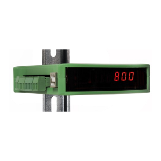
1 Mounting the indicator The indicator is designed to be mounted on 35mm DIN rail. For adequate heat dissipation 30mm of space above and below the indicator are advised. More space may be necessary for cables and connectors. 120mm 200mm 10mm 22,5mm 35mm DIN-rail... -
Page 6: Sgm800 Digitizer
To PC Config software The shields of all connected interfaces must be earthed to a reference point, e.g. the din rail. Example: When the SGM800 is powered by USB (not 24Vdc) the loadcell interface and the analog output don’t work. -
Page 7: Sgm810 Digitizer
To PC Config software The shields of all connected interfaces must be earthed to a reference point, e.g. the din rail. Example: When the SGM800 is powered by USB (not 24Vdc) the loadcell interface and the analog output don’t work. -
Page 8: Sgm820 Digitizer
To PC Config software The shields of all connected interfaces must be earthed to a reference point, e.g. the din rail. Example: When the SGM800 is powered by USB (not 24Vdc) the loadcell interface and the analog output don’t work. -
Page 9: Sgm840 Digitizer
To PC Config software The shields of all connected interfaces must be earthed to a reference point, e.g. the din rail. Example: When the SGM800 is powered by USB (not 24Vdc) the loadcell interface and the analog output don’t work. -
Page 10: Sgm850 Digitizer
To PC Config software The shields of all connected interfaces must be earthed to a reference point, e.g. the din rail. Example: When the SGM800 is powered by USB (not 24Vdc) the loadcell interface and the analog output don’t work. -
Page 11: Sgm860 Digitizer
To PC Config software The shields of all connected interfaces must be earthed to a reference point, e.g. the din rail. Example: When the SGM800 is powered by USB (not 24Vdc) the loadcell interface and the analog output don’t work. -
Page 12: First Use Of Indicator
MANUAL SGM800 2 First use of indicator Indication of Display With cover closed 1. Weigher stable 4. Output active 1-4 2. Zero active 5. Weigher value 3. Tare active 6. Profinet BUS state With cover opened 1. key 1 press <2sec.= key 2 press <2sec.=... -
Page 13: Explanation Of Front Keys
MANUAL SGM800 Explanation of front keys All keys have different functions depending if you are in weighing or menu mode. Pressing key 1 “short”. In Weighing mode: create a new zero level. In Menu mode: increase value by 1 or move up in menu. -
Page 14: Multiple Range And Multi-Interval Modes
MANUAL SGM800 Multiple Range and Multi-Interval modes There are three parameters in the configuration software (see paragraph Fout! Verwijzingsbron niet gevonden. Fout! Verwijzingsbron niet gevonden.) to modify the behavior from Multiple Range and Multi-Interval. The three parameters are listed in the table below. - Page 15 MANUAL SGM800 2.3.1 Normal Operation To use the instrument in normal operation, without multiple-range or multi-Interval, set the range to 0 parts. 2.3.2 Multiple-Range With these settings the weight indicator swithches to a lower display resolution depending on the GROSS weight on the scale. The multi-range mode can be enabled by setting the mode to “Multiple-Range”...
-
Page 16: Configuration Menu Structure
MANUAL SGM800 Configuration menu structure- - - - Fun setpoint function settings (not for SGM810 or controller) - - - ACn setpoint action settings (not for SGM810 or controller) - - - dAC Analog output settings - - - 485... -
Page 17: Display Indication At Startup
MANUAL SGM800 Display indication at startup Turn the indicator on by connecting it to the power supply. A series of display will appear: Display test. All LED will turn on to confirm that the device display is functioning correctly. Model Name. This shows the model name of the device (in this case a SGM820 Ethernet). -
Page 18: Weigher Settings
MANUAL SGM800 Weigher settings- Set up the correct indicator setting (step size and decimal point position). Turn the indicator on by connecting it to the power supply. Press key 3 for >2 sec. to get in to Configuration Menu. (In SGM810 or controller) Go to the Indicator parameters pressing key 1 <2 sec. - Page 19 MANUAL SGM800 Display step size Press key 1 <2 sec. untill you see Ind 5 and press key 2 <2 sec. Use Ind 5 to set the display step size. The step size defines the scaled parts of the weight value. The display value will be rounded off to the nearest value with a valid step size.
- Page 20 MANUAL SGM800 Press key 1 to define the point position and confirm by pressing key 3 for >2 sec. Left Right Confirm Done successfully, the following screen is visible: Press key 3 <2 sec to go back to Configuration Menu.
-
Page 21: Calibration
MANUAL SGM800 Calibration Press key 3 for >2sec. to get in to Configuration Menu. (In SGM810 or controller) Go to the Calibration parameters by pressing key 1 <2 sec. until you see - - - CAL Check and delete calibration points. - Page 22 MANUAL SGM800 When a number is shown, the deletion of one calibration point is completed and more points need to be deleted. Press key 3 >3 sec to do so. >3 sec. When all calibration points are deleted, the following screen is visible: Entering new calibration points.
- Page 23 MANUAL SGM800 The indicator now shows CP2 to calibrate the gain point (CP2). And will automatically jump to: Use key 1 and key 2 to enter the reference value. Key 1 is used for changing the number (1-9), key 2 is used for changing the position of the cursor. Load the weigher with the reference value and press key 3 >2 sec.
-
Page 24: Pi Mach Ii Software
After installing, connect the SGM800 to the computer using an A-B USB cable. Start Pi Mach II. The SGM800 will be found and connected. This is shown in the status bar (lower left corner). If there appears a USB error, connect the device manually:... - Page 25 MANUAL SGM800 The following screen appears: In the Usb tab sheet click Discover, select the SGM800 Digitizer and click OK. If this doesn’t work, make sure other USB devices like mobile phones are disconnected from the PC. In case of Windows 8, a USB driver manual is available in the Penko Suite.
- Page 26 MANUAL SGM800 Go to Start Quick setup and click the button: The following tree is shown: Use step 1 to set the Weigher Parameters: The settings you can make are: Unit: set the weigher unit (kg, lbs, T, etc.) this will be shown in PI. Decimal point: Set the decimal point to show the correct weigher value.
- Page 27 MANUAL SGM800 Use step 2 to select the type of indicator: Set the type of weighing the SGM will be used for. This will automatically set the most common filter settings to get a stable weigher signal. The options are: Unknown, Standard indicator, Fast indicator, Silo, Platform, Belt slow, Belt fast, Filling slow, Filling fast, Checkweigher slow or Checkweigher fast.
- Page 28 MANUAL SGM800 Use step 4 to set the communication (different for every type): SGM820 (Ethernet): Here you can set: Name: here you can give the SGM820a name. Example “ platform 1” . Address: set the IP-address for the SGM820. Mask: set the subnetmask for the SGM820.
- Page 29 MANUAL SGM800 SGM840 (PROFIBUS): Here you can set: Address: Set the Profibus address of the SGM840 Format: Set the format of the values sent over Profibus (Integer or Floating Point)
- Page 30 MANUAL SGM800 SGM850 (Serial): Here you can set (for both RS232 and RS422): Protocol: Set the Protocol that is used on the serial port. Options are: None, Printerm ASCII, NPV Slave, Modbus RTU, Modbus ASCII. Address: set the address of the SGM850 on the communication bus.
- Page 31 MANUAL SGM800 Use Done to finish the quick setup. Click End Quick setup: Click Enable Full setup to gain access to all settings (optional): The following tree is shown and gives access to all settings:...
-
Page 32: Main Menu
SGM810 or controllers), display the TAC code and display the CAL code. Setpoints. (this option is not available in the SGM810) The SGM800 has four outputs that can swithch on/off on different levels. These levels have to be filled in at the setpoint menu. - Page 33 TAC code (Traceable Access Code). The SGM800 has a TAC code inside. TAC code is number of times the indicator data is changed. When an indicator gets certified this number will be written on the device and is used by the controlling agency to see if the settings aren’t changed after sealing.
- Page 34 MANUAL SGM800 CAL code (Calibration counter). The SGM800 has a CAL code inside. CAL code is the number of times the calibration is changed. When an indicator gets certified this number will be written on the device and is used by the controlling agency to see if the settings aren’t changed after sealing.
-
Page 35: Configuration Menu
MANUAL SGM800 Configuration Menu Press button 3 >2 sec to enter the Configuration Menu. In the Configuration Menu the following options are available: - - - Fun setpoint function settings (not for SGM810 or controller) - - - ACn setpoint action settings (not for SGM810 or controller) - Page 36 MANUAL SGM800 3.1.1 Menu -Fun- setpoint function settings (not for SGM810 or controller) Configure the weigher mode the outputs has to swithch on press key 2 <2 sec to enter the setpoint function settings menu. Select the output you want to configure pressing key 1 <2 sec. Fun 1= output 1, Fun 2= output 2, Fun 3= output 3 and Fun 4= output 4.
- Page 37 MANUAL SGM800 3.1.2 Menu -ACn- ACn setpoint action settings (not for SGM810 or controller) To set the hysteresis for the outputs press key 2 <2 sec to enter the setpoint function settings menu. Select the output you want to configure pressing key 1 <2 sec. Acn 1= output 1, Acn 2= output 2, Acn 3= output 3 and Acn 4= output 4.
- Page 38 MANUAL SGM800 Positive hysteresis Negative hysteresis...
- Page 39 MANUAL SGM800 3.1.3 Menu -dAC- dAC Analog output settings In this menu, all analog output parameters can be set (only for SGM810 or when the analog output option is installed) options are: dAC 1 Set analog output to minimum level...
- Page 40 MANUAL SGM800 In dAC 2 you can set the analog output to its maximum level for testing purpose. Press key 2 <2 sec to set the analog output to maximum. Press key 3 <2 sec to go back. The following screen is visible: In dAC 3 you can set the analog output to a level you want for testing purpose.
- Page 41 MANUAL SGM800 The options are: Weigher 10 Weigher x 10 Fast gross 11 Fast gross x 10 Fast net 12 Fast Net x 10 Display Gross 13 Display Gross x 10 Display Net 14 Display Net x 10 Tare 15 Tare x 10...
- Page 42 MANUAL SGM800 The following screen will be visible: In dAC 6 you set the weigher end value for the analog output. At this value the analog output stops with its maximum value. Press key 2 < 2sec. to enter dAC 6.
- Page 43 The following screen will be visible: In 485 1 you set the address of the SGM800. Press key 2 < 2sec. to enter 485 1. Set the address using key 1 and key 2.. Key 1 is for changing the number (1-9), key 2 is for changing the position of the cursor.
- Page 44 Ethernet settings (SGM820 only) Protocols that can be used are Ethernet IP, Omron Fins and Modbus TCP. For protocol description please download PENKO Suite from www.penko.com In this menu, the communication settings can be set for the ethernet port. Options are:...
- Page 45 MANUAL SGM800 Increase Decrease Left Right Confirm When confirmed the following screen will be visible: In Adr 2 you set the second three numbers of the IP address you want to give the SGM820 (example: 192.168.151.112). Use key 1 and key 2 to change the num- ber Key 1 is for changing the number (1-9), key 2 is for changing the position of the cursor.
- Page 46 MANUAL SGM800 Increase Decrease Left Right Confirm When confirmed the following screen will be visible: In Sub 1 you set the first three numbers of the Subnet address you want to give the SGM820 (example: 255.255.255.000). Use key 1 and key 2 to change the number Key 1 is for changing the number (1-9), key 2 is for changing the position of the cursor.
- Page 47 MANUAL SGM800 Confirm by pressing key 3 >2 sec. Increase Decrease Left Right Confirm Wen confirmed the following screen will be visible: In Sub 4 you set the fourth three numbers of the Subnet address you want to give the SGM820 (example: 255.255.255.000).
- Page 48 MANUAL SGM800 In gAt 2 you set the second three numbers of the Gateway address you want to give the SGM820 (example: 192.168.001.001). Use key 1 and key 2 to change the number Key 1 is for changing the number (1-9), key 2 is for changing the po- sition of the cursor.
- Page 49 MANUAL SGM800 When confirmed the following screen will be visible: Starting at firmware version 1.5.0.9.0.1 the PENKO ASCII protocol is available over TCP at port 23.
- Page 50 MANUAL SGM800 3.1.6 Menu –Pb- Profibus settings (SGM840 only) For GSD file and protocol description please download PENKO Suite from www.penko.com. In this menu, the communication settings can be set for profibus. Options are: Pb 1 Profibus address Pb 2 Value mode Press key 2 <2 sec to enter the profibus settings.
- Page 51 MANUAL SGM800 In Pb 2 you set the profibus Value mode. The profibus value can be shown as Integer (direct value without decimal point) or as Floating Point (real value with decimal point). Press key 2 <2 sec. to change the mode.
- Page 52 Set the Prot using key 1 and key 2 confirm by pressing key 3 >2 sec. (options are: 1= None, 2= Printer, 3= ASCII, 4= NPV Slave, 5= Modbus-RTU, 6= Modbus ASCII). For protocol descriptions please download PENKO Suite from www.penko.com Increase Decrease Confirm...
- Page 53 MANUAL SGM800 In 232 2 you set the RS232 address of the SGM850. Press key 2 <2 sec. to enter 232 2 Set the address using key 1 and key 2 confirm by pressing key 3 >2 sec. (options are: 0-255).
- Page 54 MANUAL SGM800 In 232 4 you set the RS232 Parity of the SGM850. Press key 2 <2 sec. to enter 232 4 Set the Parity using key 1 and key 2 confirm by pressing key 3 >2 sec. (options are: 1= none, 2= odd, 3= even, 4= mark, 5=space).
- Page 55 MANUAL SGM800 In 232 6 you set the RS232 ASCII Indicator of the SGM850. This setting only takes effect when using the ASCII protocol. Press key 2 <2 sec. to enter 232 6 Set the Indicator number that you want to send out over the RS232 port by using key 1 and key 2 confirm by pressing key 3 >2 sec.
- Page 56 422 1. Set the Prot using key 1 and key 2 confirm by pressing key 3 >2 sec. (options are: 1= None, 2= Printer, 3= ASCII, 4= NPV Slave, 5= Modbus-RTU, 6= Modbus ASCII).For protocol descriptions please download PENKO Suite from www.penko.com Increase Decrease Confirm...
- Page 57 MANUAL SGM800 In 422 2 you set the RS422 address of the SGM850. Press key 2 <2 sec. to enter 422 2 Set the address using key 1 and key 2 confirm by pressing key 3 >2 sec. (options are: 0-255).
- Page 58 MANUAL SGM800 When confirmed the following screen will be visible: In 422 5 you set the RS422 Baudrate of the SGM850. Press key 2 <2 sec. to en- ter 422 5. Set the speed of the protocol by using key 1 and key 2 confirm by pres- sing key 3 >2 sec.
- Page 59 MANUAL SGM800 3.1.9 Menu -Ind- Indicator settings In this menu, the Indicator settings can be set. Options are: Ind 1 Maximum display value Ind 2 No motion band Ind 3 Stable time Ind 4 Digital overall filter Ind 5 Display step size...
- Page 60 MANUAL SGM800 Use key 1 and 2 to change the value. Key 1 is for changing the number (1-9), key 2 is for changing the position of the cursor. Confirm by pressing key 3 for >2 sec. Increase Decrease Left...
- Page 61 MANUAL SGM800 The following screen is visible: Use key 1 and 2 to change the value. Key 1 is for changing the number (1-9), key 2 is for changing the position of the cursor. Confirm by pressing key 3 for >2 sec.
- Page 62 MANUAL SGM800 The following screen is visible: In Ind 5 you set the display step size. The step size defines the scaled parts of the weight value. The display value will be rounded off to the nearest value with a valid step size.
- Page 63 MANUAL SGM800 In Ind 6 you set the decimal point. The decimal point defines the point position of the weight value. To change the decimal point press key 2 < 2 sec. The following screen is visible: Press key 1 to define the point position and confirm by pressing key 3 for >2 sec.
- Page 64 Down Confirm The following screen is visible: In Ind 8 you set the operation mode of the SGM800. Set the operation mode of the unit to Industrial or Certified. In Industrial mode it’s always possible to change the indicator parameters and calibration. In certified mode the unit will be sealed by marks and also the weighing parameters will be blocked to satisfy to the cali- bration laws.
- Page 65 MANUAL SGM800 In Ind 9 you set the sample rate of the indicator. The sample rate is the refresh- ment speed of the weigher signal. Options are: 10, 20, 25, 50, 100, 200, 400, 800, 1600 samples/sec. To change the sample rate press key 2 < 2 sec.
- Page 66 MANUAL SGM800 3.1.10 Menu -rng- 5.1 - - - rng Multi range/interval settings In this menu, the multi range/interval can be set. Options are: Rng 1 Number of display divisions Rng 2 Maximum auto range step size Rng 3 Auto range reset option Press key 2 <2 sec to enter the multi range/interval settings.
- Page 67 MANUAL SGM800 Use key 1 and 2 to change the value. Key 1 is for changing the number (1-9), key 2 is for changing the position of the cursor. Confirm by pressing key 3 for >2 sec. Down Left Right...
- Page 68 MANUAL SGM800 Example Max Step: Displayed range Step size If the settings are: Step size = 1, Range = 100 and Max. Step = 50, 0-100 the table on the right shows the 100-200 accompanying step size with which the...
- Page 69 MANUAL SGM800 3.1.11 Menu -FIL- - - FIL Filter settings In this menu, the filter settings can be set. The display filter will damp the weigher signal to the display to get a calm display view. Options are: FIL 1...
- Page 70 MANUAL SGM800 In FIL 2 you can set the display filter factor. Set the strength of the filter. 0dB means no effect and –50 is the strongest damping. This parameter works together with FIL 1. Choose between -: 0dB, 1: -6dB, 2: -12dB, 3: -18dB, 4: -24dB, 5: -30dB, 6: -36dB, 7: -42dB and 8: -50dB.
- Page 71 MANUAL SGM800 In FIL 4 you can set the number of the indicator shown in the display. Choose a number between 1 and 19. When using the FIL parameters use 4, 5, 12 or 13. The following screen is visible:...
- Page 72 MANUAL SGM800 3.1.12 Menu -dSF- Digital filter settings In this menu, the digital filter settings can be set. This filter is a 2 order filter. The filter effects all signals up to and including the cutoff frequency. Options are: dSF 1...
- Page 73 MANUAL SGM800 The following screen is visible: In dSF 2 you can set the Cutoff frequency. Determines the range used for filtering the signal. Choose between oFF, 1.0Hz, 1.4Hz, 2.5Hz, 5.0Hz, 10.0Hz, 20.0Hz and 40Hz. Press key 2 <2 sec. to change the cutoff frequency range.
- Page 74 MANUAL SGM800 3.1.13 Menu -PCL- Use key 1 and 2 to change the value. Key 1 is for changing the number (1-9), key 2 is for changing the position of the cursor. Confirm by pressing key 3 for >2 sec.
- Page 75 MANUAL SGM800 In PcL 1 you can set the polaritiy of the input range. Un=Unipolar mode the input range for load cells is –0.2 mV/V to + value set at Range. Bi=Bipolar mode the input range for load cells is –value set at Range to + value set at Range.Press key 2 <2 sec. To change the polaritity og the input range.
- Page 76 MANUAL SGM800 In PcL 3 you can set the Input offset. Choose between choose a sample value between –50000 and 50000. Press key 2 <2 sec. to change the input offset The following screen is visible: Use key 1 and 2 to change the value. Key 1 is for changing the number (1-9), key 2 is for changing the position of the cursor.
- Page 77 MANUAL SGM800 3.1.14 Menu -CAL- 5.2 - - - CAL Calibration settings In this menu, the Calibration settings can be set. Options are: CAL 1 Add calibration point CAL 2 Check weigher information CAL 3 Show/remove calibration points CAL 4...
- Page 78 MANUAL SGM800 First calibrate the zero point (CP1). Make sure the weigher is unloaded and press key 3 >2 sec. The indicator now shows CP2 to calibrate the gain point (CP2). And will automatically jump to: Use key 1 and key 2 to enter the reference value. Key 1 is used for changing the number (1-9), key 2 is used for changing the position of the cursor.
- Page 79 MANUAL SGM800 Use key 1 <2 sec. to toggle between the actual weight and the actual weight x10. Use key 2 <2 sec. to toggle between the actual weight and the ADC value. When finished press key 3< 2 sec.
- Page 80 MANUAL SGM800 When a number is shown, the deletion of one calibration point is completed and more points need to be deleted. Press key 3 >3 sec to do so. >3 sec. When all calibration points are deleted, the following screen is visible: In CAL 4 you can set a Deadload compensation.
- Page 81 MANUAL SGM800 Normally, the deadload is zero, but it is possible to change the line position if there is weight on the scale. To do so, edit the actual weigh value to the new known value. When the new dead load is set the following screen is visible:...
- Page 82 MANUAL SGM800 3.1.15 Menu -tCL- Theoretic calibration In this menu, the Theoretic calibration settings can be set. Here you can set a calibration without using a reference weight. For this you only need the specification sheets of the used loadcells. Options are:...
- Page 83 MANUAL SGM800 Use key 1 and key 2 to enter the maximum load of the loadcell(s). Key 1 is used for changing the number (1-9), key 2 is used for changing the position of the cursor. And press key 3 >2 sec.to set the maximum load.
- Page 84 MANUAL SGM800 The following screen is visible: In tcL 3 you can set the loadcell sensitivity for loadcell 2. This information can be found on the datasheet delivered with the loadcell. Press key 2 <2 sec. to set the loadcell sensitivity.
- Page 85 MANUAL SGM800 Use key 1 and key 2 to enter the sensitivity of loadcell 3. Key 1 is used for changing the number (1-9), key 2 is used for changing the position of the cursor. Sensitivity has to be filled in as 0.00000 mV/V. Press key 3 >2 sec. to set the sensitivity of the loadcell.
- Page 86 MANUAL SGM800 3.1.16 Menu -gCL- gCL Geographic calibration In this menu, the Geographic calibration settings can be set. Here you can set a geographic information of the loadcells filled in al tCL. Options are: gCL 1 Origin latitude gCL 2...
- Page 87 MANUAL SGM800 Down Left Right Confirm The following screen is visible: In gcL 2 you can set the origin elevation of the loadcell. This is the geographic elevation of where the loadcell is manufactured. Press key 2 <2 sec. to set the origin elevation.
- Page 88 MANUAL SGM800 The following screen is visible: Use key 1 and key 2 to enter the location latitude of the loadcell(s). Key 1 is used for changing the number (1-9), key 2 is used for changing the position of the cursor. And press key 3 >2 sec.to set the location latitude.
- Page 89 MANUAL SGM800 3.1.17 Menu -CLo- CLo Date and time configuration In Clock, you can set the internal date and time. Press key 2 <2 sec to enter Clock. The following screen is visible: Set the date. Use key 1 and key 2 to change the number Key 1 is for changing the number (1-9), key 2 is for changing the position of the cursor.
- Page 90 MANUAL SGM800 3.1.18 Menu -rcl- Recall In Recall, you can reset all parameters back to factory settings. Press key 2 <2 sec to enter Recall. The following screen is visible. Press key 2 <2 sec. The following screen is visible.
- Page 91 Starting at firmware version 1.6.0.9.0.3 a backup of the device configuration can be made within the device. A password is required for the backup. Contact PENKO for this password. The backup can only be made using Pi Mach II manage. Enter the password in the service code field.
- Page 92 MANUAL SGM800 3.1.19 Menu -SoF- Firmware update In SoF, you can set the SGM800 in boot mode for software update. Press key 2 <2 sec to enter Boot mode. The following screen is visible: Press key 3 >2 sec to set the SGM800 in Boot mode.
-
Page 93: Firmware Update
MANUAL SGM800 4 Firmware update Connect the SGM to the computer through USB. Start PI Mach II. Set communi- cation to USB. Start the Firmware Update Manager. Click Open and select the PIP file. Click Search For Devices and select the device with source “0”. - Page 94 Press key 2 <2 sec to enter Boot mode. The following screen is visible: Press key 3 >2 sec to set the SGM800 in Boot mode. Now click Firmware Update to start the update. The SGM will reboot automatically and the Firmware Update Manager will show...
-
Page 95: Event Log
Calibrations. Event Logs can be viewed via Pi Mach II Manage: How you can connect your SGM800 to PI Mach II Manage is explained in chapter 3 of this manual. Enter the Event number at “Entry Number” and confirm with Enter or the Apply button. - Page 96 MANUAL SGM800 complete Event log memory.
-
Page 97: Alibi Memory
SGM800 MFL, checked weight of the SGM800 CHK and actual weigher value of the SGM800 Indicator. In the SGM800 Belt the Alibi Memory has no function. The Alibi memory can be viewed via Pi Mach II Manage: How you can connect your SGM800 to PI Mach II Manage is explained in chapter 3 of this manual. - Page 98 MANUAL SGM800 Enter the Alibi number at “Entry Number” and confirm with Enter or the Apply but- ton. The Alibi data is shown. It shows the weigher value that is saved with the time and date it is saved on.
-
Page 99: Sgm800 Controller Chk Alibi Memory
MANUAL SGM800 SGM800 Controller CHK Alibi Memory In the SGM800 CHK the Alibi Memory can be enabled in the configuration. For more information about the configuration please check the SGM800 Check weigher manual supplement. To get the Alibi information enter the Alibi number at “Entry Number” and confirm with Enter or the Apply button. -
Page 100: Sgm800 Controller Mfl Alibi Memory
MANUAL SGM800 SGM800 Controller MFL Alibi Memory In the SGM800 MFL the Alibi Memory can be enabled in the configuration. For more information about the configuration please check the SGM800 Mono Filler manual supplement. To get the Alibi information enter the Alibi number at “Entry Number” and confirm with Enter or the Apply button. -
Page 101: Error Codes
MANUAL SGM800 7 Error Codes Error Code Description Solution 2001 Parameter error Invalid entry, choose a valid value Invalid entry, choose value within range 2005 Input value is not valid Wait for stable weigher signal and try 2101 Weigher not stable... -
Page 102: Weigher Error Codes
MANUAL SGM800 Bad calibration 2119 Change calibration levels Weigher error Codes Error Code Description Solution CCCCCC No proper calibration available Check calibration setting Check loadcell UUUUUU Underflow Check platform construction Check loadcell OOOOOO Overflow Check platform construction Display overflow; ======... -
Page 103: Profibus Protocol Description
MANUAL SGM800 Profibus Protocol Description Note that the GSD Profibus file for the SGM840 Indicator differ from SGM840 controller GSD file. Use PSGM0E28.GSD This file is available in the Penko Suite. Inputs to PLC D word 32 bit Weight register... -
Page 104: Standard Factory Settings
MANUAL SGM800 Standard Factory Settings Description Display Value Your setting Setpoint function Fun 1 Fun 2 Fun 3 Fun 4 Setpoint action Acn 1 000,010 Acn 2 000,010 Acn 3 000,010 Acn 4 000,010 Analog output dAC 4 dAC 5 000.000... - Page 105 MANUAL SGM800 Description Display Value Your setting Ethernet gAT 1 gAT 2 gAT 3 gAT 4 Indicator Ind 1 10.009 Ind 2 Ind 3 1.000 Ind 4 Ind 5 Ind 6 - - - . - - - Ind 7...
- Page 106 MANUAL SGM800 Pre-calibration Pcl 1 Pcl 2 Pcl 3 Theoretic calibration tCL 1 10.000 tCL 2 0.000 tCL 3 0.000 tCL 4 0.000 tCL 5 0.000 Geographic calibration gCL 1 52.00 gCL 2 gCL 3 52.00 gCL 4...
- Page 107 MANUAL SGM800 Appendix I Description Definition Weight filtered net weigher value that can react on mulit range/interval Fast Gross unfiltered gross weigher value Fast Net unfiltered net weigher value Display Gross filtered gross weigher value Display Net filtered net weigher value...
- Page 108 About PENKO At PENKO Engineering we specialize in weighing. Weighing is inherently chemically correct, independent of consistency, type or temperature of the raw material. This means that weighing any kind of material guaranties consistency and thus, it is essential to sustainable revenue generation in any industry.
Need help?
Do you have a question about the SGM800 and is the answer not in the manual?
Questions and answers