Sign In
Upload
Download
Table of Contents
Contents
Add to my manuals
Delete from my manuals
Share
URL of this page:
HTML Link:
Bookmark this page
Add
Manual will be automatically added to "My Manuals"
Print this page
×
Bookmark added
×
Added to my manuals
Manuals
Brands
PENKO Manuals
Measuring Instruments
SGM700 Series
Manual
PENKO SGM700 Series Manual
Hide thumbs
Also See for SGM700 Series
:
Manual
(84 pages)
1
2
3
Table Of Contents
4
5
6
7
8
9
10
11
12
13
14
15
16
17
18
19
20
21
22
23
24
25
26
27
28
29
30
31
32
33
34
35
36
37
38
39
40
41
42
43
44
45
46
47
48
49
50
51
52
53
54
55
56
57
58
59
60
61
62
63
64
65
66
67
68
69
70
71
72
73
74
75
76
77
78
79
80
81
82
83
84
85
86
87
88
89
90
91
92
93
94
95
96
97
98
99
100
101
102
103
104
105
106
page
of
106
Go
/
106
Contents
Table of Contents
Bookmarks
Table of Contents
Table of Contents
1 Loadcell Power Connection
SGM700 Basic Digitizer
SGM710 Digitizer Analog
SGM720 Digitizer Ethernet
SGM730 Digitizer CAN
SGM740 Digitizer Profibus
SGM750 Digitizer Serial
2 Indication of Display
3 Explanation of Front Keys
4 First Use of Indicator
Configuration Menu Structure
Weigher Setting
Calibration
First Use by Using PI Mach II Software
5 Main Menu
Setpoints (Not for SGM710)
TAC (Traceable Acces Code)
CAL (Calibration Counter)
6 Configuration Menu
Setpoint Function Settings (Not for SGM710)
Setpoint Action Settings (Not for SGM710)
Analog Output Settings
Local Bus Communication Settings (RS485)
Ethernet Settings (SGM720 Only)
Can Bus Port Settings (SGM730 Only)
Profibus Settings (SGM740 Only)
RS232 Port Settings (SGM750 Only)
RS422 Port Settings (SGM750 Only)
Indicator Settings
Multi Range/Interval Settings
Filter Settings
Digital Filter Settings
Pre-Calibration Settings
Calibration Settings
Theoretic Calibration
Geographic Calibration
Date and Time Configuration (SGM750 Only)
Recall
Firmware Update
7 Firmware Update
8 Error Codes
Weigher Error Codes
10 Profibus Protocol Description
11 Standard Factory Settings
Appendix I
Notes
Advertisement
Quick Links
1
Sgm710 Digitizer Analog
2
Sgm720 Digitizer Ethernet
3
Calibration
4
Calibration Settings
Download this manual
PENKO Engineering BV
The Leading Experts In Weighing & Dosing
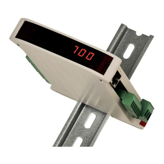
SGM700
Digitizer
Manual
For more information visit
www.penko.com - technical support - literature library
Table of
Contents
Previous
Page
Next
Page
1
2
3
4
5
Advertisement
Table of Contents
Need help?
Do you have a question about the SGM700 Series and is the answer not in the manual?
Ask a question
Questions and answers
Related Manuals for PENKO SGM700 Series
Measuring Instruments PENKO SGM700 Manual
(84 pages)
Measuring Instruments PENKO SGM740 Manual
(106 pages)
Measuring Instruments PENKO SGM720 Manual
(106 pages)
Measuring Instruments PENKO SGM800 Manual
(113 pages)
Measuring Instruments PENKO SGM800 Manual
(108 pages)
Measuring Instruments PENKO 1020 FMD Manual
(110 pages)
This manual is also suitable for:
Sgm730
Sgm740
Sgm750
Sgm710
Sgm720
Table of Contents
Save PDF
Print
Rename the bookmark
Delete bookmark?
Delete from my manuals?
Login
Sign In
OR
Sign in with Facebook
Sign in with Google
Upload manual
Upload from disk
Upload from URL


Need help?
Do you have a question about the SGM700 Series and is the answer not in the manual?
Questions and answers