
Related Manuals for PENKO 1020 FMD


Summary of Contents for PENKO 1020 FMD
- Page 1 1020 FMD PENKO Engineering B.V. Your Partner for Fully Engineered Factory Solutions Manual: 1020 FMD...
- Page 2 If this Instruction Manual is not may affect the continued safe operation of the correct manual for the PENKO product your processes. The use of non-specified you are using, call 0031(0)318-525630 for a ‘look-alike’...
- Page 3 Proper relay use and configuration is the responsibility of the user. Do not operate this instrument without the front cover being secured. Refer any installation, operation or servicing issues to qualified personnel. WWW.PENKO.COM PENKO Engineering B.V. is an ETC Company Email: info@PENKO.com...
-
Page 4: Table Of Contents
1020 FMD Table of Contents Introduction ............................6 In the box ............................6 Needed for use ..........................6 Overview ........................... 7 Connections ..........................9 Power supply ........................9 Load cell ........................... 10 USB ........................... 11 Analog output ........................12 Digital inputs ........................13 Digital outputs ......................... - Page 5 1020 FMD 6.3.3 Communication ......................61 6.3.4 Digital inputs ......................68 6.3.5 Digital outputs ......................68 6.3.6 Analog output ......................71 6.3.7 Passwords ......................... 73 6.3.8 Screen ........................75 6.3.9 Clock ......................... 79 6.3.10 Printer ........................80 6.3.11 Factory recall ......................84 Control ..........................
-
Page 6: Introduction
1020 FMD Introduction The PENKO 1020 FMD is a compact comprehensive Force Measurement Device. In the box The box contains the following items: 1 x 10²⁰ FMD device 1 x rubber ring for mounting purpose 2 x clip for mounting purpose ... -
Page 7: Overview
1020 FMD 1 Overview Option 1: Option 2:... - Page 8 1020 FMD Number Description TFT display 320 x 240 Keypad OPTION: None || Serial + CAN bus || Profibus Ethernet connection USB connection Digital inputs (3) Digital outputs (4) 24VDC power supply OPTION: Analog output Load cell connection RS232/RS422 connection...
-
Page 9: Connections
1020 FMD 2 Connections This chapter describes the connections of the 1020 FMD. Before connecting the device to a computer using USB, make sure the USB driver is installed. 2.1 Power supply Power the device using a Class 2 or Limited Power Source, rate 18 – 32 VDC, 0.4A@24VDC... -
Page 10: Load Cell
1020 FMD 2.2 Load cell Property Description Wiring With sense Type of sense Passive Excitation voltage 5 VDC Sensitivity 0,1 μV/d Selectable ranges 1 mV/V | 1,5 mV/V | 2 mV/V | 2,5 mV/V | 3 mV/V Input voltage @3mV/V... -
Page 11: Usb
PENKO configuration software. Before connecting the device to a computer using USB, make sure the USB driver is installed. The driver is included in the PENKO configuration PC applications, see chapter PC applications. Only 1 protocol is supported over USB:... -
Page 12: Analog Output
1020 FMD 2.4 Analog output The analog output can be used as mA output in the following ranges and react to an indicator value. Range Description 16 bit DAC value 0 - 20 mA The minimum and maximum output of the analog output... -
Page 13: Digital Inputs
1020 FMD 2.5 Digital inputs The device has 3 digital. The inputs can be switched PNP or NPN with 18 - 28 VDC. The inputs can be programmed as Hold, Peak Hold, Key Lock etc. -
Page 14: Digital Outputs
1020 FMD 2.6 Digital outputs The device has 4 digital outputs that can be used for an AC and DC power circuit up to 35V/0.5A. The outputs can be programmed as setpoints with a programmable hysteresis and function like Track, Peak, Valley etc. -
Page 15: Ethernet
The Ethernet connection can be used for communication with Pi Mach II and for the following protocols: Protocol Description BusLink PENKO Protocol to connect the device to a PENKO FLEX controller EthernetIP Protocol to connect to SCADA/PLC Omron FINS Protocol to connect to SCADA/PLC... -
Page 16: Can Bus
1020 FMD 2.9 CAN Bus The CAN Bus can be used for the PENKO BusLink protocol, a protocol to connect the 1020 FMD to a PENKO FLEX controller. Connection Description CAN High Ground CAN Low Shield The CANopen protocol is not available... -
Page 17: Profibus
1020 FMD 2.10 Profibus Profibus is available on the option board. Pin No. Symbol Name Description SHIELD Shield protective ground Reserved for power RxD/TxD-P Receive/Transmit data P CNTR-P Control P DGND Data ground Voltage plus Reserverd for power RxD/TxD-N Receive/Transmit data N... -
Page 18: Rs232/Rs422
RS232 and RS422 are available on the option board and can be used for the following protocols: Protocol Description Printer PENKO protocol to connect a ASCII/plain-text printer ASCII PENKO protocol for ASCII communication NPV Slave PENKO Protocol used for follow displays... - Page 19 1020 FMD RS232 communication: RS422 communication with multiple devices:...
-
Page 20: Display And Keypad
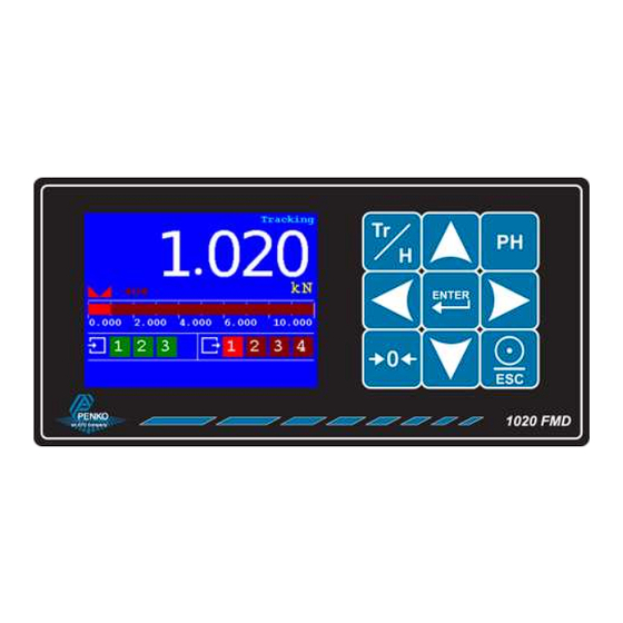
1020 FMD 3 Display and keypad The display contains the following indications: Number Description Indicator in stable range [] Zero active [] Range/Interval active Bar graph indication Digital input active indication (3 inputs) Digital output active indication (4 outputs) Measured value Type of value shown on the display (Tracking, Hold, T.I.R, Peak, Valley) *... - Page 21 1020 FMD Hold function Peak, Valley and T.I.R. function...
- Page 22 1020 FMD The display indications in menu mode: Number Description Active buttons for current menu item TAC and CAL code* Menu level * TAC and CAL code TAC stands for Traceable Access Code. A number of settings are only available after entering this code.
- Page 23 1020 FMD The keys have the following functions: Tracking / Hold Toggle between Tracking mode and Hold mode. Peak Hold Show Peak Hold mode. Enter / Menu Adjust levels. Press > 2 seconds to enter configuration menu. In menu mode, press to confirm setting.
-
Page 24: Pc Applications
1020 FMD 4 PC applications For easy configuration and monitoring, two PC applications are available as download. PDI Client and Pi Mach II. In the following chapters, Pi Mach II is used to explain the 1020 FMD functionality. www.penko.com/software 4.1 PDI Client PDI client is a small cross-platform application that only works with USB communication. -
Page 25: Pi Mach Ii
1020 FMD 4.2 Pi Mach II Pi Mach II is a comprehensive Windows application that works with USB and Ethernet communication and has more functionality compared to PDI Client. The tree structure configuration of PDI Client is available in this program. Other features are backup and restore, firmware updates and a build in oscilloscope to analyze signals for different filter settings. -
Page 26: First Use
1020 FMD 5 First use For first use, the following settings are important: Unit indication Decimal point position Step size Maximum load Calibration Communication This chapter describes how to adjust these settings with the configuration software and on the device itself. - Page 27 For example the live force information: In the tree, select PENKO 1020. The properties of this tree node are shown in the right screen. The first use settings are available under Start Quick setup...
- Page 28 1020 FMD Select Step1, Indicator Parameters Unit Set the unit of measurement, for example kN or N. This will be shown everywhere the measured force is displayed or printed. Decimal point Select the position of the decimal point. This setting will be used everywhere the measured force is displayed or printed.
- Page 29 1020 FMD Example: Measured value is 2005 kN. Step size Displayed value 2005 2006 2005 2010 2000 2000 2000 2000 Maxload Set the force the indicator will use as maximum. If the measured force is higher than the maximum load, the display will show ======...
- Page 30 1020 FMD Select Step2, Indicator setup Application A number of predefined configurations with specific filter settings are available. These configurations don’t affect the settings made in step 1. They only affect the filter settings. Available options Unknown Standard indicator Fast indicator When setting up an installation, select the appropriate configurations and start fine tuning it with the options available in the Full setup.
- Page 31 1020 FMD Select Step 3, Calibrate With this step a two-point calibration can be made. The unit indication and decimal point position are a result of the settings in step 1. Live gross This shows the gross indicator value. When no calibration is available this will show cccccc Live signal This shows the voltage generated by the connected load cell or force sensor.
- Page 32 1020 FMD Select Step 4, Communication Every available communication port has its own settings. The available ports depend on the option board. Ethernet This shows the MAC address of the device. This number cannot be changed. Name Domain Name System (DNS). A name can be given to the device to access the device in the Ethernet network by name instead of by IP address.
- Page 33 1020 FMD Ethernet BusLink BusLink is a PENKO protocol to connect the device to a PENKO FLEX series device. The device parameters like indicator values and I/O status become available in the PENKO FLEX. A BusLink network can contain up to 40 PENKO devices (8 addresses x 5 sub addresses).
- Page 34 1020 FMD RS232 / RS422 The available options for RS232 and RS422 are the same and therefore described only once. Protocol Select the protocol for the serial port. Available options None Printer ASCII NPV Slave MODBUS-RTU MODBUS-ASCII Address Set the address of the port for identification in the network.
- Page 35 1020 FMD Parity Set the parity needed for the selected protocol. Available options None Even Mark Space Baudrate Set the baud rate needed for the selected protocol. Available options 1200 2400 4800 9600 19200 38400 57600 115200 Indicator This option is only active when ASCII is selected as protocol. The value of the selected indicator will be sent out over the communication port.
- Page 36 1020 FMD BusLink is a PENKO protocol to connect the device to a PENKO FLEX series device. The device parameters like indicator values and I/O status become available in the PENKO FLEX. A BusLink network can contain up to 40 PENKO devices (8 addresses x 5 sub addresses).
- Page 37 1020 FMD Buslink Subaddress Set the BusLink sub address. Available options Baudrate Set the baud rate equal to the baud rate of the connected PENKO FLEX. Available options 100k 125k 250k 500k The CANopen protocol is not available...
- Page 38 1020 FMD Profibus Address Set the Profibus address for the device. Range 0…255 Format Set the format for the values sent over Profibus. Available options Integer Floating point Select Done and click End Quick setup This will finish the quick setup.
-
Page 39: Using The Device
1020 FMD 5.2 Using the device The menu structure in the device has no quick setup like the configuration software. The first use items can be set along with all other settings. Main Menu From the main screen, press the Enter button for 2 seconds to enter the Main Menu. - Page 40 1020 FMD Edit a value Use the arrow buttons to edit a value. Select the digit with the Left and Right button. Increase the value with the Up button. Decrease the value with the Down button. Use the Enter button to confirm the whole value.
- Page 41 1020 FMD → → Change character set Indicator parameters The indicator parameters from the quick setup can be set as follows:...
- Page 42 1020 FMD Enter the TAC as shown on the right bottom corner of the screen using the arrow buttons - apply with the Enter button Here the Unit, Step size, Decimal point and Max load can be set The predefined settings of step 2 in the quick setup are not available in the...
- Page 43 1020 FMD Calibration The calibration from the quick setup can be performed as follows: Enter the CAL as shown on the right bottom corner of the screen using the arrow buttons - apply with the Enter button...
- Page 44 1020 FMD Make sure the load cell or force sensor is not loaded and is stable before pressing Enter Make sure the load cell or force sensor is loaded with the reference weight and is stable before pressing Enter...
- Page 45 1020 FMD Enter the reference weight - apply with the Enter button The device is now calibrated...
-
Page 46: Full Setup
A full menu structure can be found in the attachment. In the tree, select PENKO 1020. The properties of this tree node are shown in the right screen. The full settings are available under Enable Full setup... -
Page 47: Live
1020 FMD 6.1 Live Live shows various live parameters of the device. Node Description Indicator Live indicator values and indicator status Digital inputs Live status of the 3 digital inputs (0 = OFF, 1 = ON) Digital outputs Live status of the 4 digital outputs (0 = OFF, 1 = ON) -
Page 48: System Setup
1020 FMD 6.3 System Setup System Setup contains the full device configuration. 6.3.1 Service Service is for PENKO employees only. 6.3.2 Indicator Indicator contains the indicator parameters and calibration. PARAMETERS To enter the parameters, enter the shown TAC and confirm with Enter or the Apply button:... - Page 49 1020 FMD Properties Properties contain the basic weigher parameters. Name Set a name to identify the device in a multiple device setup (optional). Maxload Set the force the indicator will use as maximum. If the measured force is higher than the...
- Page 50 1020 FMD Step Select the step size. This setting defines the scaled parts of the force value. The display value will be rounded to the nearest value with a valid step size. Available options: Available options Example: Measured value is 2005 kN.
- Page 51 1020 FMD Unit Set the unit of measurement, for example kN or N. This will be shown everywhere the measured force is displayed or printed. Stable The stable settings determine when the indicator accepts the current value as stable. Stable range Set the range the indicator has to be in for the set time to give a stable signal.
- Page 52 1020 FMD Range/Interval Set the indicator to change its step size when the measured force reaches a certain value. Range Set the number of divisions when the indicator has to display with the next step size. Auto ranging is disabled when range is set to 0.
- Page 53 1020 FMD Range No. Displayed range Step size Range: 1 0 - 100 Range: 2 100 - 200 Range: 3 200 - 500 Range: 4 500 - 1000 Range: 5 1000 - 2000 Range: 6 2000 - 5000+ The number of ranges depends on the selected max step size. In this case there are 6 possible ranges.
- Page 54 1020 FMD Overall filter Select an overall filter. This will affect all indicator signals in the device. 0dB is no filtering. -48dB gives the strongest damping. Available options 0 dB -6 dB -12 dB -18 dB -24 dB -30 dB...
- Page 55 1020 FMD Cut Off Select the cutoff frequency for the selected filter type. Available options 1,0 Hz 1,4 Hz 2,5 Hz 5,0 Hz 10 Hz 20 Hz 40Hz Moving Average Set the moving average frequency for the selected filter. Range 0…50...
- Page 56 1020 FMD Display Tracking: Filter range Set the range where the filter is active. Display Tracking: Filter damping Select the strength of the filter. 0dB is no filtering. -48dB gives the strongest damping. Available options 0 dB -6 dB -12 dB...
- Page 57 1020 FMD CALIBRATION To enter the calibration, enter the shown CAL and confirm with Enter or the Apply button: The parameters are now shown in the tree: Force calibration Force calibration contains the calibration settings. Display shows the current display values.
- Page 58 1020 FMD Signal The current voltage, from the load cell or force sensor, in millivolts. The current ADC value. Points show the stored calibration points. Up to 10 calibration points can be stored to realize a multi-point calibration. Add/Replace point is used to add a calibration point.
- Page 59 1020 FMD Deadload can be set to pull the whole measuring line back to zero. The zero point could be different because of some modification on the scale or dirt. Normally, the dead load is zero, but it’s possible to change the line position if there’s weight on the scale.
- Page 60 1020 FMD Output Set the output value as mentioned on the datasheet. Zero balance Set the zero balance value as mentioned on the datasheet. Type Set a name for the load cell or force sensor. Max load Set the maximum load as mentioned on the datasheet.
-
Page 61: Communication
1020 FMD 6.3.3 Communication Every available communication port has its own settings. The available ports depend on the option board. Ethernet This shows the MAC address of the device. This number cannot be changed. Name Domain Name System (DNS). A name can be given to the device to access the device in the Ethernet network by name instead of by IP address. - Page 62 1020 FMD Ethernet BusLink BusLink is a PENKO protocol to connect the device to a PENKO FLEX series device. The device parameters like indicator values and I/O status become available in the PENKO FLEX. A BusLink network can contain up to 40 PENKO devices (8 addresses x 5 sub addresses).
- Page 63 1020 FMD RS232 / RS422 The available options for RS232 and RS422 are the same and therefore described only once. Protocol Select the protocol for the serial port. Available options None Printer ASCII NPV Slave MODBUS-RTU MODBUS-ASCII Address Set the address of the port for identification in the network.
- Page 64 1020 FMD Parity Set the parity needed for the selected protocol. Available options None Even Mark Space Baudrate Set the baud rate needed for the selected protocol. Available options 1200 2400 4800 9600 19200 38400 57600 115200 Indicator This option is only active when ASCII is selected as protocol. The value of the selected indicator will be sent out over the communication port.
- Page 65 1020 FMD BusLink is a PENKO protocol to connect the device to a PENKO FLEX series device. The device parameters like indicator values and I/O status become available in the PENKO FLEX. A BusLink network can contain up to 40 PENKO devices (8 addresses x 5 sub addresses).
- Page 66 1020 FMD Buslink Subaddress Set the BusLink sub address. Available options Baudrate Set the baud rate equal to the baud rate of the connected PENKO FLEX. Available options 100k 125k 250k 500k The CANopen protocol is not available...
- Page 67 1020 FMD Profibus Address Set the Profibus address for the device. Range 0…255 Format Set the format for the values sent over Profibus. Available options Integer Floating point...
-
Page 68: Digital Inputs
1020 FMD 6.3.4 Digital inputs The digital inputs can execute a function. Function Select a function for the input. Available options Description None No function Zero Set Set indicator to zero Zero Reset Reset indicator from zero Hold Store current value as hold value... - Page 69 1020 FMD Action Hysteresis Set the hysteresis for each output. The hysteresis can be positive or negative.
- Page 70 1020 FMD Function Function Select the indicator the output has to react on. Available options Description Fast Tracking Unfiltered tracking value Tracking Filtered tracking value Peak Peak hold value - the highest measured value Valley Valley hold value - the lowest measured value...
-
Page 71: Analog Output
1020 FMD 6.3.6 Analog output The analog output is an option. The settings are only available when the DAC module is placed. Manual Manual output level Set the percentage for the output when manual control is enabled. Manual control Enable manual control of the output. - Page 72 1020 FMD Minimum level Set the indicator value the analog output will set as 0.00% output. Maximum level Set the indicator value the analog output will set as 100.00% output. Function Select the indicator the output has to react on.
-
Page 73: Passwords
1020 FMD Example: Minimum level Maximum level Function Range 0,000 kN 10,000 kN Tracking 4-20 mA If the tracking value is 0,000 kN, the analog output will send out 4 mA (0%) If the tracking value is 5,000 kN, the analog output will send out 12 mA (50%) ... - Page 74 1020 FMD Try to enter a menu item in the system setup menu The password screen appears - enter the password to gain access to the menu item The menu item is now available - when no actions are performed the access is blocked...
-
Page 75: Screen
1020 FMD 6.3.8 Screen In Screen all screen options can be set. Buttons The Zero, Track/Hold, Peak Hold and Esc/Print button can be enabled or disabled. To the other buttons a function can be assigned. By default, T.I.R. is assigned to the Up button and Valley Hold is assigned to the Down button. - Page 76 1020 FMD Led Bar Bar Style Select the style of the led bar. Bar Peak and Dot Peak show a peak value indication for a second when the value drops. Available options Description Bar Peak Dot Peak Bar Reverse Dot Reverse Minimum Set the minimum value for the led bar.
- Page 77 1020 FMD Example: Bar Style Minimum Lower Margin Upper Margin Maximum Step 0,000 2,000 8,000 10,000 1,000 Value below the margin is yellow: Value within the margin is green: Value above the margin is red: Maximum Set the maximum value for the led bar.
- Page 78 1020 FMD Keybeep Enable or disable the key beep. When enabled, every key press is confirmed with a beep. When disabled, only entering the main menu (pressing enter for 2 seconds) gives a beep. Available options Language Select the language for the device. This only applies to the device. The configuration software is always in English.
-
Page 79: Clock
1020 FMD Indicator Select the indicator that is shown on the display. In case any other indicator than Display is selected, the buttons for showing the Tracking, Hold, T.I.R., Peak hold and Valley hold value are disabled. Available options Description... -
Page 80: Printer
1020 FMD Set Time Set the time in the indicated format to correct the device time. Set Date Set the date in the indicated format to correct the device date. An easy way to synchronize time and date is to use the Clock function in Pi Mach II. - Page 81 1020 FMD Layout Select the layout for printing. The Ticket layout is a predefined format. The Line layout prints every measurement on a new line. For both layouts a 24 and 40 columns format is present. 24 columns 40 columns...
- Page 82 1020 FMD Rows For the ticket layout, the number of rows represents the empty lines after each ticket. For the line layout, the number of rows represents the total number of rows for the header and the lines. When set to 1 for example, each printed line gets a header. When set to 10 for example, each 6 lines get a header (in case the header is 4 lines).
- Page 83 1020 FMD Header Header 1...4 Optionally set a header for the printer ticket. Up to 4 lines can be programmed. Footer Footer 1…4 Optionally set a footer for the printer ticket. Up to 4 lines can be programmed. Ethernet printer...
-
Page 84: Factory Recall
A backup of the device configuration can be made within the device. A password is required for the backup. Contact PENKO for this password. When using Pi Mach II manage to make a backup, enter this password in the service code field to enable the backup option. -
Page 85: Control
1020 FMD 6.4 Control Control has various functions to control the indicator. Node Description Zero Set Set the indicator value to zero Zero Reset Set the indicator value back to its original value Hold Reset Reset the stored hold value... -
Page 86: Alibi Memory And Event Log
1020 FMD 7 Alibi Memory and Event Log The Alibi and Event Log support the following features: Automatically store system events Create alibi records View, search and print alibi records and event logs 7.1 Alibi Memory Alibi records are generated by a user action. To generate records, go to the Printer Settings menu and set Port to Alibi memory. - Page 87 1020 FMD Entry Number Enter the number of the desired record and conform with Enter or the Apply button. The record is shown. Record The type of record. A record can be a Header or a Data record. A header records is the title of the record and shows a tag, date and time.
- Page 88 1020 FMD Example of a printer layout of these records: The alibi records are also available on the device. Press 2 seconds...
- Page 89 1020 FMD Use the buttons for the following actions: Last Jump to the last entry of the list. Filter Filter the list on date or UID. Select All to undo the filtering. First/Clear Jump to the first entry of the list.
- Page 90 1020 FMD Filtering the alibi memory: Press the Enter button. The following screen is shown: Use the “From Date” and “To Date” to set a date filter, or type in a UID to filter on 1 specific record. Leave the filter screen with the Escape button and the filter is applied.
-
Page 91: Event Log
System events are generated automatically by the system. These events can be seen but cannot be erased. Erasing of the records can only be performed by PENKO. Events are created for logging software updates, calibration changes, parameter changes, clearing the alibi memory, etc. - Page 92 1020 FMD Print This will print the total event log to a connected printer. On the device it’s possible to print only a part of the event log. This is explained further on. Examples: Number Record Tag/Code Date/Value Time/Unit Header...
- Page 93 1020 FMD Use the buttons for the following actions: Last Jump to the last entry of the list. Filter Filter the list on date or UID. Select All to undo the filtering. First Jump to the first entry of the list.
- Page 94 1020 FMD Filtering the event log: Press the Enter button. The following screen is shown: Use the “From Date” and “To Date” to set a date filter, or type in a UID to filter on 1 specific record. Leave the filter screen with the Escape button and the filter is applied.
-
Page 95: Firmware Update
Update the application firmware by Ethernet or USB connection. 8.1 Ethernet Connect the 1020 FMD to the computer through Ethernet. Start PI Mach II. Set communication to Ethernet. Also see the Pi Mach II manual. Start the Firmware Update Manager. -
Page 96: Usb
The 1020 FMD will reboot automatically and the Firmware Update Manager will show Updated. 8.2 USB Connect the 1020 FMD to the computer through USB. Start PI Mach II. Set communication to USB. Also see the Pi Mach II manual. - Page 97 1020 FMD Now click Firmware Update to start the update. The 1020 FMD will reboot automatically and the Firmware Update Manager will show Updated.
-
Page 98: Backup And Restore
9 Backup and restore With the 1020 FMD it’s possible to make a backup of the software as it’s installed in the device. The software will be saved as an FDI file which stands for Flex Data Image. The Backup data assures that when the device fails, a replacement device can be programmed as a copy of the original device. - Page 99 1020 FMD...
-
Page 100: Standard Factory Settings
1020 FMD 10 Standard factory settings Description Display Value Your setting Properties Name … Unit label Step Decimal point 0,000 Max Load 10,009 kN Sample Rate 1600/s Stable condition Range 0,002 kN Time 1,00 s Zero tracking Range 0,000 kN... -
Page 101: Error Codes
1020 FMD 11 Error codes Error code Description Solution 2001 Parameter error Invalid entry, choose valid value 2005 Input value is not valid Invalid entry, choose value within range 2101 Weigher not stable Wait for stable and try again 2102... -
Page 102: Specifications
1020 FMD 12 Specifications Type Description Wiring With sense Type of sense Passive Power supply 18-32 VDC; 7,5 W max. Excitation voltage 5 VDC Sensitivity 0,1 μV/d Selectable ranges 1 mV/V | 1,5 mV/V | 2 mV/V | 2,5 mV/V | 3 mV/V... - Page 103 1020 FMD...
-
Page 104: Index
1020 FMD Index Ethernet connection ....17 Manual 100.00% ......74 Manual control ......74 Manual off ......... 74 Add/Replace .......60 Manual output level ....74 Address Ethernet ......64 Margin ........85 Factory recall ......87 Address Ethernet BusLink ...65 Mask subnet ....... - Page 105 1020 FMD Stable time ......... 53 Step Led bar ....... 80 Step size ........52 Range (range/interval) ....54 UID alibi ........90 Stopbits RS232/422 ....66 Range analog out ......75 UID event ........94 Sub address Ethernet BusLink ..65 Range input range.......63...
-
Page 106: Appendix I - Menu Structure
1020 FMD Appendix I - Menu structure... - Page 107 1020 FMD...
- Page 108 1020 FMD...
-
Page 109: Appendix Ii - Communication Protocols
PENKO protocol over Ethernet, serial and Ethernet (UDP) USB connection used for communication PENKO TP / PDI RS232/422 between the device and the configuration software. Protocol descriptions and needed files can be downloaded from the PENKO website. www.penko.com... - Page 110 A complete overview you will find on: www.penko.com/dealers PENKO Engineering B.V. ▪ Schutterweg 35, NL 6718XC Ede ▪ Tel +31 (0) 318525630 ▪ Fax +31 (0) 31852971 ▪ info@penko.com Web ▪ www.penko.com ▪ 7600M1062 ▪ Copyright © 2015 ETC All rights reserved.
Need help?
Do you have a question about the 1020 FMD and is the answer not in the manual?
Questions and answers