
Related Manuals for PENKO SGM700


Summary of Contents for PENKO SGM700
- Page 1 PENKO Engineering BV The Leading Experts In Weighing & Dosing SGM700 Digitizer Manual For more information visit www.penko.com - technical support - literature library...
- Page 2 If this Instruction Manual is not the processes. The use of non-specified ‘look- correct manual for the Penko product you alike’ substitution parts may result in the are using, call 0031(0)318-525630 for a risk of fire, electrical hazards, or improper replacement copy.
- Page 3 Proper relay use and configuration is the responsibility of the user. Do not operate this instrument without the front cover being secured. Refer any installation, operation or servicing issues to qualified personnel. WWW.PENKO.COM Penko is an ETC Company e-mail: info@penko.com...
-
Page 4: Table Of Contents
TABLE OF CONTENT Chapter Page 1.Indication of display 2. Explanation of front keys 3. Loadcell power conection 3.1 SGM700 basic digitizer 3.2 SGM710 digitizer analog 3.3 SGM720 digitizer Ethernet 3.4 SGM730 digitizer CAN 3.5 SGM740 digitizer Profibus 3.6 SGM750 digitizer Serial 4. - Page 5 SGM700 Digitizer TABLE OF CONTENT Chapter Page 6.17 Firmware update 7. Firmware update 8. Error codes 8.1 Weigher error codes 9. ASCII 9.1 ASCII protocol format 9.2 ASCII protocol commands 10. Profibus protocol description 11. Standard factory settings Appendix I...
-
Page 6: Indication Of Display
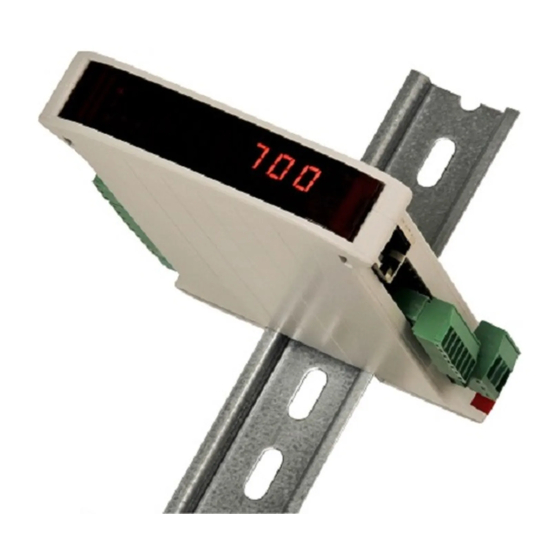
SGM700 Digitizer 1. Indication of Display With cover closed 1. Weigher stable 4. Output active 1-4 2. Zero active 5. Weigher value 3. Tare active With cover opened key 1 press <2sec.= key 2 press <2sec.= key 1 press >2sec.= key 2 press >2sec.=... -
Page 7: Explanation Of Front Keys
SGM700 Digitizer 2. Explanation of front keys All keys have different functions depending if you are in weighing or menu mode. Pressing key 1 “short”. In Weighing mode: create a new zero level. In Menu mode: increase value by 1 or move up in menu. -
Page 8: Loadcell Power Conection
SGM700 Digitizer 3. Load cell / power connection 3.1 SGM700 basic digitizer... -
Page 9: Sgm710 Digitizer Analog
SGM700 Digitizer 3. Load cell / power connection 3.2 SGM710 digitizer analog... -
Page 10: Sgm720 Digitizer Ethernet
SGM700 Digitizer 3. Load cell / power connection 3.3 SGM720 digitizer ethernet... -
Page 11: Sgm730 Digitizer Can
SGM700 Digitizer 3. Load cell / power connection 3.4 SGM730 digitizer CAN... -
Page 12: Sgm740 Digitizer Profibus
SGM700 Digitizer 3. Load cell / power connection 3.5 SGM740 digitizer Profibus... -
Page 13: Sgm750 Digitizer Serial
SGM700 Digitizer 3. Load cell / power connection 3.6 SGM740 digitizer Serial... -
Page 14: First Use Of Indicator
SGM700 Digitizer 4. First use of indicator 4.1 First use of indicator -Weigher settings- Set up the correct indicator setting (step size and decimal point position). The start Turn the indicator on by connecting it to the power supply. Press key 3 for >2 sec. to get in to Configuration Menu. - Page 15 SGM700 Digitizer First use of indicator -continue- When the maximum net weight value is set succesfully, the following screen is visible: Display step size Press key 1 <2 sec. untill you see Ind 5 and press key 2 <2 sec.
- Page 16 SGM700 Digitizer First use of indicator -continue- Press key 1 to define the point position and confirm by pressing key 3 for >2 sec. Left Right Confirm Done succesfully, the following screen is visible: Press key 3 <2 sec to go back to Configuration Menu.
-
Page 17: Calibration
SGM700 Digitizer First use of indicator -continue- 4.2 First use of indicator -Calibration- Press key 3 for >2sec. to get in to Configuration Menu. Go to the Calibration parameters by pressing key 1 <2 sec. until you see - - - CAL Check and delete calibration points. - Page 18 SGM700 Digitizer First use of indicator -continue- Calibration Settings -continue- When a number is shown, the deletion of one calibration point is completed and more points need to be deleted. Press key 3 >3 sec to do so. >3 sec.
- Page 19 SGM700 Digitizer First use of indicator -continue- Calibration Settings -continue- The indicator now shows CP2 to calibrate the gain point (CP2). And will automatically jump to: Use key 1 and key 2 to enter the reference value. Key 1 is used for changing the number (1-9), key 2 is used for changing the position of the cursor.
-
Page 20: Main Menu
CAL code. 5.1 Setpoints. The SGM700 has four outputs that can switch on/off on different levels. These levels have to be filled in at the setpoint menu. Press key 3 <2 sec. to go into the Main menu. -
Page 21: Tac (Traceable Acces Code)
5.2 TAC code (Traceable Acces Code). The SGM700 has a TAC code inside. TAC code is number of times the indicator data is changed. When an indicator gets certified this number will be written on the device and is used by the controlling agency to see if the settings aren’t changed after sealing. -
Page 22: Cal (Calibration Conter)
Main Menu -continue- 5.2 CAL code (Calibration counter). The SGM700 has a CAL code inside. CAL code is the number of times the calibration is changed. When an indicator gets certified this number will be written on the device and is used by the controlling agency to see if the settings aren’t changed after sealing. -
Page 23: Configuration Menu
SGM700 Digitizer 6. Configuration Menu Press button 3 >2 sec to enter the Configuration Menu. In the Configuration Menu the following options are available: - - - Fun setpoint function settings - - - ACn setpoint action settings - - - dAC... -
Page 24: Setpoint Function Settings
SGM700 Digitizer Configuration Menu -Fun- 6.1 - - - Fun setpoint function settings Configure the weiger mode the outputs has to switch on press key 2 <2 sec to en- ter the setpoint function settings menu. Select the output you want to configure pressing key 1 <2 sec. Fun 1= output 1, Fun 2= output 2, Fun 3= output 3 and Fun 4= output 4. -
Page 25: Setpoint Action Settings
SGM700 Digitizer Configuration Menu -ACn- 6.2 - - - ACn setpoint action settings To set the hysteresis for the outputs press key 2 <2 sec to enter the setpoint function settings menu. Select the output you want to configure pressing key 1 <2 sec. Acn 1= output 1, Acn 2= output 2, Acn 3= output 3 and Acn 4= output 4. -
Page 26: Analog Output Settings
SGM700 Digitizer Configuration Menu -dAC- 6.3 - - - dAC Analog output settings In this menu, all analog output parameters can be set. Options are: dAC 1 Set analog output to minimum level dAC 2 Set analog output to maximum level... - Page 27 SGM700 Digitizer Configuration Menu -dAC- -continue- In dAC 2 you can set the analog output to its maximum level for testing purpo- se.Press key 2 <2 sec to set the analog output to maximum. Press key 3 <2 sec to go back.
- Page 28 SGM700 Digitizer Configuration Menu -dAC- -continue- The options are: Weigher 10 Fast gross x 10 Fast gross 11 Fast Net x 10 Fast net 12 Gross x 10 Gross 13 Net x 10 14 Tare x 10 Tare 15 Peak x 10...
- Page 29 SGM700 Digitizer Configuration Menu -dAC- -continue- The following screen will be vissable: In dAC 6 you set the weigher end value for the analog output. At this value the analog output stops with its maximum value. Press key 2 < 2sec. to enter dAC 6.
-
Page 30: Local Bus Communication Settings
The following screen will be vissable: In 485 1 you set the address of the SGM700. Press key 2 < 2sec. to enter 485 1. Set the address using key 1 and key 2.. Key 1 is for changing the number (1-9), key 2 is for changing the position of the cursor. -
Page 31: Profibus Settings (Sgm740 Only)
The following screen will be vissable: In Pb 1 you set the profibus address of the SGM700. Press key 2 <2 sec. to enter Pb 1. Set the address using key 1 and key 2 confirm by pressing key 3 >2 sec. - Page 32 SGM700 Digitizer Configuration Menu -Pb- -continue- In Pb 2 you set the profibus Value mode. The profibus value can be shown as Integer (direct value without decimal point) or as Floating Point (real value with decimal point). Press key 2 <2 sec. to change the mode.
-
Page 33: Ethernet Serrings (Sgm720 Only)
SGM700 Digitizer Configuration Menu -Eth- 6.6 - - - Eth Ethernet settings (SGM720 only) In this menu, the communication settings can be set for the ethernet port. Options are: Adr 1 First three numbers of the IP address Adr 2... - Page 34 In Adr 2 you set the second three numbers of the IP address you want to give the SGM700 (example: 192.168.151.112). Use key 1 and key 2 to change the number Key 1 is for changing the number (1-9), key 2 is for changing the position of the cursor.
- Page 35 In Sub 2 you set the second three numbers of the Subnet address you want to give the SGM700 (example: 255.255.255.000). Use key 1 and key 2 to change the number Key 1 is for changing the number (1-9), key 2 is for changing the po-...
- Page 36 In Sub 3 you set the third three numbers of the Subnet address you want to give the SGM700 (example: 255.255.255.000). Use key 1 and key 2 to change the number Key 1 is for changing the number (1-9), key 2 is for changing the po- sition of the cursor.
- Page 37 In gAt 2 you set the second three numbers of the Gateway address you want to give the SGM700 (example: 192.168.001.001). Use key 1 and key 2 to change the number Key 1 is for changing the number (1-9), key 2 is for changing the po- sition of the cursor.
- Page 38 In gAt 4 you set the fourth three numbers of the Gateway address you want to give the SGM700 (example: 192.168.001.001). Use key 1 and key 2 to change the number Key 1 is for changing the number (1-9), key 2 is for changing the po- sition of the cursor.
-
Page 39: Indicator Settings
SGM700 Digitizer Configuration Menu -Ind- 6.7 - - - Ind Indicator settings In this menu, the Indicator settings can be set. Options are: Ind 1 Maximum display value Ind 2 No motion band Ind 3 Stable time Ind 4 Digital overall filter... - Page 40 SGM700 Digitizer Configuration Menu -Ind- -continiue- The following screen is vissable: Use key 1 and 2 to change the value. Key 1 is for changing the number (1-9), key 2 is for changing the position of the cursor. Confirm by pressing key 3 for >2 sec.
- Page 41 SGM700 Digitizer Configuration Menu -Ind- -continiue- The following screen is vissable: In Ind 3 you set the Stable time Indicator gives stable signal when weigher value is stable within the range set in Ind 2 and time set with Ind 3.
- Page 42 SGM700 Digitizer Configuration Menu -Ind- -continiue- To change the filter press key 2 < 2 sec. The following screen is vissable: Use key 1 change the filter. Confirm by pressing key 3 for >2 sec. Down Confirm The following screen is vissable: In Ind 5 you set the display step size.
- Page 43 SGM700 Digitizer Configuration Menu -Ind- -continiue- Use key 1 to select the correct step size. Choose between 1, 2, 5, 10, 20, 50 and confirm by pressing key 3 for >2 sec. Example step size: weigher value is 2005 kg...
- Page 44 SGM700 Digitizer Configuration Menu -Ind- -continiue- The following screen is vissable: In Ind 7 you set the Display refreshment speed. The Display refreshment speed defines the times the weigher value is refresht per second. Options are: 1, 2, 3, 5, 10, 25, 50.
- Page 45 SGM700 Digitizer Configuration Menu -Ind- -continiue- In Ind 8 you set the operation mode of the SGM700. Set the operation mode of the unit to Industrial or Certified. In Industrial mode it’s always possible to change the indicator parameters and calibration. In certified mode the unit will be sealed by marks and also the weighing parameters will be blocked to satisfy to the cali- bration laws.
-
Page 46: Multi Range/Interval Settings
SGM700 Digitizer Configuration Menu -rng- To change the sample rate press key 2 < 2 sec. The following screen is vissable: Press key 1 to choose the sample rate and confirm by pressing key 3 for >2 sec. Down Confirm The following screen is vissable: 6.8 - - - rng... - Page 47 SGM700 Digitizer Configuration Menu -rng- -continue- The following screen is vissable: In rng 1 you set the number of display divisions. Set the number of divisions when the indicator has to display with the next step size. Auto ranging starts with step size set at Ind 5 and is disabled when range size is set to 0.
- Page 48 SGM700 Digitizer Configuration Menu -rng- -continue- To change the maximum step size press key 2 < 2 sec. The following screen is vissable: Use key 1 change the filter. Key 1 is for changing the number. Confirm by pressing key 3 for >2 sec.
-
Page 49: Filter Settings
SGM700 Digitizer Configuration Menu -FIL- In rng 3 you set the auto range reset option. Choose between: oF: Multi Range = the highest shown step size will be reseted after the signal has been lower or equal to zero on: Mulit Interval = the highest shown step size will be reseted after the signal reaches the previous range. - Page 50 SGM700 Digitizer Configuration Menu -FIL- -continue- The following screen is visible: In FIL 1 you can set the display filter band. Set the band where the filter is active. This parameter works together wit FIL 2. Choose a value between –99999 kg and 999999 kg.
- Page 51 SGM700 Digitizer Configuration Menu -FIL- -continue- The following screen is visible: Use key 1 change the filter. Confirm by pressing key 3 for >2 sec. Down Confirm The following screen is visible: In FIL 3 you set the band within the indicator will show 0. When the indicator is certified, this parameter will be disabled.
-
Page 52: Digital Filter Settings
SGM700 Digitizer Configuration Menu -dSF- 6.10 - - - dSF Digital filter settings In this menu, the digital filter settings can be set. This filter is a 2 order filter. The filter effects all signals up to and including the cutoff frequency. Options are:... - Page 53 SGM700 Digitizer Configuration Menu -dSF- -continue- The following screen is visible: In dSF 2 you can set the Cutoff frequency. Determines the range used for filtering the signal. Choose between oFF, 1.0Hz, 1.4Hz, 2.5Hz, 5.0Hz, 10.0Hz, 20.0Hz and 40Hz. Press key 2 <2 sec. to change the cutoff frequency range.
-
Page 54: Pre-Calibration Settings
SGM700 Digitizer Configuration Menu -PCL- Use key 1 and 2 to change the value. Key 1 is for changing the number (1-9), key 2 is for changing the position of the cursor. Confirm by pressing key 3 for >2 sec. - Page 55 SGM700 Digitizer Configuration Menu -PCL- -continue- In PcL 1 you can set the polaritiy of the input range. Un=Unipolar mode the input range for load cells is –0.2 mV/V to + value set at Range. Bi=Bipolar mode the input range for load cells is –value set at Range to + value set at Range.Press key 2 <2 sec.
- Page 56 SGM700 Digitizer Configuration Menu -PCL- -continue- Use key 1 change the sensitiviy. Confirm by pressing key 3 for >2 sec. Down Confirm The following screen is visible: In PcL 3 you can set the Input offset. Choose between choose a sample value between –50000 and 50000.
-
Page 57: Calibration Settings
SGM700 Digitizer Configuration Menu -CAL- The following screen is visible: The following screen is visible: To recall the factory settings press key 3 >2 sec. To cancel press key 3 <2 sec. Cancel Recall The following screen is visible: 6.12 - - - CAL Calibration settings In this menu, the Calibration settings can be set. - Page 58 SGM700 Digitizer Configuration Menu -CAL- -continue- Press key 2 <2 sec to enter the calibration settings. The following screen is visible: In CAL 1 you can set the calibration points for the weigher. Press key 2 <2 sec. to set the calibration points.
- Page 59 SGM700 Digitizer Configuration Menu -CAL- -continue- The indicator now shows CP2 to calibrate the gain point (CP2). And will automatically jump to: Use key 1 and key 2 to enter the reference value. Key 1 is used for changing the number (1-9), key 2 is used for changing the position of the cursor.
- Page 60 SGM700 Digitizer Configuration Menu -CAL- -continue- Use key 1 <2 sec. to toggle between the actual weight and the actual weight x10. Use key 2 <2 sec. to toggle between the actual weight and the ADC value. When finished press key 3< 2 sec.
- Page 61 SGM700 Digitizer Configuration Menu -CAL- -continue- When a number is shown, the deletion of one calibration point is completed and more points need to be deleted. Press key 3 >3 sec to do so. >3 sec. When all calibration points are deleted, the following screen is visible: In CAL 4 you can set a Deadload compensation.
-
Page 62: Theoretic Calibration
SGM700 Digitizer Configuration Menu -tCL- Normally, the deadload is zero, but it is possible to change the line position if there is weight on the scale. To do so, edit the actual weigh value to the new known value. When the new dead load is set the following screen is visible: 6.13 - - - tCL... - Page 63 SGM700 Digitizer Configuration Menu -tCL- -continue- Press key 2 <2 sec to enter the theoreatic calibration settings. The following screen is visible: In tcL 1 you can set the maximum loadcell load. When more then one loadcell is used all loadcells should have the same maximum load. Press key 2 <2 sec. to set the maximum load.
- Page 64 SGM700 Digitizer Configuration Menu -tCL- -continue- The following screen is visible: Use key 1 and key 2 to enter the sensitivitiy of loadcell 1. Key 1 is used for changing the number (1-9), key 2 is used for changing the position of the cursor.
- Page 65 SGM700 Digitizer Configuration Menu -tCL- -continue- Use key 1 and key 2 to enter the sensitivitiy of loadcell 2. Key 1 is used for changing the number (1-9), key 2 is used for changing the position of the cursor. Sensitivity has to be filled in as 0.00000 mV/V. Press key 3 >2 sec. to set the sensitivity of the loadcell.
- Page 66 SGM700 Digitizer Configuration Menu -tCL- -continue- The following screen is visible: In tcL 5 you can set the loadcell sensitivity for loadcell 4. This information can be found on the datasheet deliverd with the loadcell. Press key 2 <2 sec. to set the loadcell sensitivity.
-
Page 67: Geographic Calibration
SGM700 Digitizer Configuration Menu -gCL- 6.14 - - - gCL Geographic calibration In this menu, the Geographic calibration settings can be set. Here you can set a geographic information of the loadcells filled in al tCL. Options are: gCL 1... - Page 68 SGM700 Digitizer Configuration Menu -gCL- -continue- Down Left Right Confirm The following screen is visible: In gcL 2 you can set the origin elevation of the loadcell. This is the geographic elevation of where the loadcell is manufactured. Press key 2 <2 sec. to set the origin elevation.
- Page 69 SGM700 Digitizer Configuration Menu -gCL- -continue- In gcL 3 you can set the location latiude of the loadcell(s). This is the geographic latitude of where the loadcell is going to be used. Press key 2 <2 sec. to set the location latitude.
-
Page 70: Date And Time Configuration (Sgm750 Only)
SGM700 Digitizer Configuration Menu –CLo- Use key 1 and key 2 to enter the location elevation of the loadcell(s). Key 1 is used for changing the number (1-9), key 2 is used for changing the position of the cursor. And press key 3 >2 sec.to set the location latitude. Choose value between –1000 and 30000 meter... -
Page 71: Recall
SGM700 Digitizer Configuration Menu -rcl- The following screen is visible: Set the time. Use key 1 and key 2 to change the number Key 1 is for changing the number (1-9), key 2 is for changing the position of the cursor. Confirm by pressing key 3 >2 sec. -
Page 72: Firmware Update
The SGM700 will reboot after he file system is reset. 6.17 - - - SoF Firmware update In SoF, you can set the SGM700 in boot mode for software update. Press key 2 <2 sec to enter Boot mode. The following screen is visible:... -
Page 73: Firmware Update
SGM700 Digitizer 7. Firmware update Connect the SGM to the computer through USB. Start PI Mach II. Set communi- cation to USB. Start the Firmware Update Manager. Click Open and select the PIP file. Click Search For Devices and select the device with source “0”. - Page 74 Press key 2 <2 sec to enter Boot mode. The following screen is visible: Press key 3 >2 sec to set the SGM700 in Boot mode. Now click Firmware Update to start the update. The SGM will reboot automatically and the Firmware Update Manager wil show...
-
Page 75: Error Codes
SGM700 Digitizer 8. Error Codes Error Code Description Solution 2001 Parameter error Invalid entry, choose a valid value 2005 Input value is not valid Invalid entry, choose value within 2101 Weigher not stable Wait for stable weigher signal and try... -
Page 76: Weigher Error Codes
SGM700 Digitizer 8.1 Weigher error Codes Error Code Description Solution CCCCCC No proper calibration available Check calibration setting Check loadcell UUUUUU Underflow Check platform construction Check loadcell OOOOOO Overflow Check platform construction Display overflow; ====== Exceed maximum display Reduce load on platform value (max. -
Page 77: Ascii Protocol Commands
SGM700 Digitizer 9.2 ACSII -Protocol Commands- Command Respons strings Operation OP <number><CR> OK<CR>/ERR<CR> Open channel connection CL<CR> Close channel connection SZ<CR> OK<CR>/ERR<CR> Set Zero value OK<CR>/ERR<CR> RZ<CR> Reset Zero value OK<CR>/ERR<CR> ST<CR> Set Tare OK<CR>/ERR<CR> RT<CR> Reset Tare OK<CR>/ERR<CR> PT<value><CR>... - Page 78 SGM700 Digitizer 5. ACSII -protocol commands - continue- Command Respons strings Operation LN<CR> N+00000+00000SSCC<CR>/ERR<CR> Get net+fast net , status & checksum Get long extended net (net x 10) + LX<CR> X+00000+00000SSCC<CR>/ERR<CR> extended gross (gross x 10), status & checksum SD<CR>...
-
Page 79: Profibus Protocol Description
SGM700 Digitizer 10. Profibus Protocol Description Module = "weight" 0x28, 0x1E ; gross 32 bits inputs ; net 32 bits inputs ; tare 32 bits inputs ; status 16 bits inputs ; cmd 8 bits inputs ; level1 32 bits outputs ;... -
Page 80: Standard Factory Settings
SGM700 Digitizer 11. Standard Factory Settings Description Display Value Your setting Setpoint function Fun 1 Fun 2 Fun 3 Fun 4 Setpoint action Acn 1 000,010 Acn 2 000,010 Acn 3 000,010 Acn 4 000,010 Analog output dAC 4 dAC 5 000.000... - Page 81 SGM700 Digitizer 7. Standard Factory Settings -continue- Description Display Value Your setting Ethernet gAT 1 gAT 2 gAT 3 gAT 4 Indicator Ind 1 10.009 Ind 2 Ind 3 1.000 Ind 4 Ind 5 Ind 6 - - - . - - -...
- Page 82 SGM700 Digitizer 7. Standard Factory Settings -continue- Description Display Value Your setting Pre-calibration Pcl 1 Pcl 2 Pcl 3 Theoretic calibration tCL 1 10.000 tCL 2 0.000 tCL 3 0.000 tCL 4 0.000 tCL 5 0.000 Geographic calibration gCL 1 52.00...
-
Page 83: Appendix I
SGM700 Digitizer Appendix I Description Definition Weight filtered net weigher value that can react on mulit range/interval Fast Gross unfiltered gross weigher value Fast Net unfiltered net weigher value Gross filtered gross weigher value filtered net weigher value Tare tare value... - Page 84 PENKO Engineering B.V. | Schutterweg 35, 6718 XC Ede | The Netherlands | Tel 0031 (0)318 525630 | Fax 0031 (0)318 529715 | info@penko.com | www.penko.com All product information and specifications are subject to change without prior notice. Copyright © 2012 PENKO.
Need help?
Do you have a question about the SGM700 and is the answer not in the manual?
Questions and answers