
Related Manuals for Assa Abloy 840C-50


Summary of Contents for Assa Abloy 840C-50
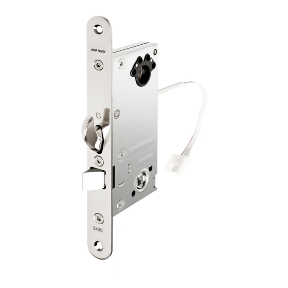
- Page 1 Motor Lock Manual 840C-50, 841C-50, 841C-35, 851C-35, 851C-50, 850C-50 ASSA ABLOY, the global leader in door opening solutions.
-
Page 2: Table Of Contents
Quick guide ....11 För manual på svenska, var god vänd. ASSA ABLOY, the global leader in door opening solutions, dedicated to satisfying end-user needs for security, safety and convenience. -
Page 3: Installation
Installation Mark centerline A (Face plate) when you have decided the position of the lockcase. Mark B and C Use a 20 mm drill bit to get the correct depth for the lockcase, 82 mm for 50 mm backset and 48 mm for 35 backset. Do not use force to push the lockcase into the mortice. -
Page 4: Connection
Connection To connect a motor lock to the Hi-O bus a White CAN high four wire cable is used; two for power and Brown CAN low two for communication. Green + 12–24VDC stab Yellow 0 V Use supplied cable EA226 (10m), with connector, at installation. -
Page 5: Latch Bolt 840C/850C
Latch bolt 840C/850C Unmount the screws (Torx T20). Be careful the pin and socket can fall out. Unmount the plastic. Turn the latchbolt. Assembly the plastic. Assembly the pin and socket. Assembly the forend. Assembly the screws (Torx T20). Door monitor The placement of the door monitor is under the date mark on the forend... -
Page 6: Technical Data
Technical data Currency consumption (mA) Lock Type Idle Running Assa Motor Lock 50mA Max 445 mA at 841C/840C/850C/851C 24 VDC Cable Type: EA226, 10 m Max length Total 50 m Cable length Cable area 12V 20 m 0,3 mm 30 m 0,4 mm 40 m 0,5 mm... -
Page 7: Accessories
Accessories ASSA 840C-50 841C-35 841C-50 851C-35 850C-50 851C-50 Cylinder type Round, oval Oval Strike plate 1487-1, -2*, -3, -4, -5 1487-8* Cable EA226* EA226* Cable loop EA280, EA281* EA280, EA281* Thumb turn Round thumb turn cyl. 13 Oval thumb turn cyl. 03 Oval thumb turn cyl. -
Page 8: Maintenance Of Motor Locks
Maintenance of motor locks – Hinges, framework and door Follow this manual thoroughly to maintain characteristics of the motor threshold (sill). lock. Do not diverge from this manual – Door closer. without advice from ASSA. NB!! • Never use lubricants containing Warranty fails if product is: •... -
Page 9: Class 4 Och Class 5
Class 4 and Class5 To meet the Class 4 and Class 5, the following requirements must be met. For Class 4 and Class 5 requires that the controller is installed in a protected space with at least grade 3 locking. DAC564 controller must be installed in the SSF 3522 mode. - Page 10 25 (851-35) 25 (851-35) 22 (841-35) 22 (841-35) R5 (4x) R5 (4x) R5 (4x) R5 (4x) Drill for screw Drill for screw Cylinder Cylinder 4,0 x 25mm 4,0 x 25mm ∅10 ∅10 Drill for screw Drill for screw 4,0 x 25mm 4,0 x 25mm R5,5 (2x) R5,5 (2x)
-
Page 11: Quick Guide
Quick guide Installation and initiation/pairing of Hi-O motor lock and DAC Connect the cables of the motor lock to DAC (White = CAN H, Brown = CAN L, Green = 12 V, Yellow = 0 V). Make sure that the termination jumper link in DAC is set to ON. - Page 12 Initiation Door monitor switch in motor lock and fail safe/safe secure electric strike Door monitor input DIP 7 – Electric strike Explanation/result. Closed Sensor in motor lock active Safe secure function on electric strike (Normal mode). Sensor in motor lock active Fail safe function on electric strike. Open Sensor in motor lock inactive Fail safe function on electric strike.
- Page 13 Quick guide Configuration of DAC as control unit 17-24V AC/DC Vit/White Brun/Brown Grön/Green Gul/Yellow Dag/Natt, Day/Night Öppna/Open DIP8=ON, DIP7=OFF: Function of relays and inputs KP1 in DAC530 and DAC564 Relay & Input Function Relay Out (Lock) Electric strike Relay Out (Alarm) Alarm Bypass IN 13&14 Door monitor Door position in...
- Page 14 DIP8=ON, DIP7=OFF: Function of relays and inputs DAC530 board DIP 3 DIP 4 Function Relay Relay 13 & 14 11 & 12 (Lock) (Alarm) Door monitor Button Standard Electric strikes Alarm Bypass Door position Open EMLA Bolt out. Bolt in. Door position Open The relay...
Need help?
Do you have a question about the 840C-50 and is the answer not in the manual?
Questions and answers