Table of Contents
Advertisement
Quick Links
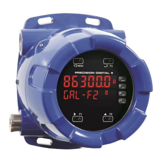
ProtEX-MAX PD8-6300 Pulse Input
Rate/Totalizer, Counter and Tachometer
Instruction Manual
•
Fully-Approved Explosion-Proof Flow Rate/Totalizers
•
Pulse, Open Collector, NPN, PNP, TTL, Switch Contact, Sine Wave (Coil), Square Wave Inputs
•
Dual-Line 6-Digit Display, 0.6" (15 mm) & 0.46" (12 mm)
•
SafeTouch Through-Glass Button Programming
•
Display Mountable at 0°, 90°, 180°, & 270°
•
Isolated 5, 10 or 24 VDC Flowmeter Power Supply
•
Gate Function for Rate Display of Slow Pulse Rates
•
4 Relays with Interlocking Capability + Isolated 4-20 mA Output Option
•
Free PC-Based, On-Board, MeterView Pro USB Programming Software
•
SunBright Display Standard Feature; Great for Outdoor Applications
•
Display Rate & Total at the Same Time
•
Rate in Units per Second, Minute, Hour, or Day
•
Total, Grand Total or Non-Resettable Grand Total
•
Front Panel or Remote Total Reset
•
Password Protection for Total Reset
•
Total Stored in Non-Volatile Memory
•
Assign Any Relay or 4-20 mA Output for Rate or Total
•
K-Factor, Internal Scaling, or External Calibration
•
4-20 mA Output Option Converts the Pulse Input to an Isolated 4-20 mA Output
•
Operating Temperature Range: -40 to 60°C (-40 to 140°F)
•
FM Approved as Explosion-Proof / Dust-Ignition-Proof / Flame-Proof
•
CSA Certified as Explosion-Proof / Dust-Ignition-Proof / Flame-Proof
•
ATEX and IECEx Certified as Flame-Proof
•
Input Power Options: 85-265 VAC / 90-265 VDC or 12-24 VDC / 12-24 VAC
•
Programmable Display, Function Keys & Digital Inputs
•
Flanges for Wall or Pipe Mounting
•
Explosion-Proof, IP68, NEMA 4X Die-Cast Aluminum Enclosure
•
On-Board RS-485 Serial Communications
•
Modbus RTU Communication Protocol Standard
•
Password Protection
•
Four 3/4" NPT Threaded Conduit Openings (Two Plugs Installed)
•
3-Year Warranty
PRECISION DIGITAL CORPORATION
233 South Street • Hopkinton MA 01748 USA
Tel (800) 343-1001 • Fax (508) 655-8990
www.predig.com
MeterView Pro
USB Install
Advertisement
Table of Contents

Related Manuals for Precision Digital Corporation ProtEX-MAX PD8-6300


Summary of Contents for Precision Digital Corporation ProtEX-MAX PD8-6300
- Page 1 ProtEX-MAX PD8-6300 Pulse Input Rate/Totalizer, Counter and Tachometer Instruction Manual MeterView Pro USB Install • Fully-Approved Explosion-Proof Flow Rate/Totalizers • Pulse, Open Collector, NPN, PNP, TTL, Switch Contact, Sine Wave (Coil), Square Wave Inputs • Dual-Line 6-Digit Display, 0.6" (15 mm) & 0.46" (12 mm) •...
- Page 3 Limited Warranty Precision Digital Corporation warrants this product against defects in material or Watch MeterView Pro Software Video at workmanship for the specified period under www.predig.com/meterviewpro...
-
Page 4: Table Of Contents
PD8-6300 Pulse Input Rate/Totalizer, Counter & Tachometer Instruction Manual Table of Contents Introduction ......................7 Ordering Information ..................7 Key Features ....................... 9 Specifications ....................15 General ......................15 Pulse Inputs ....................16 Rate/Totalizer ....................16 Relays ......................17 USB Connection ................... 17 Isolated 4-20 mA Transmitter Output ............ - Page 5 PD8-6300 Pulse Input Rate/Totalizer, Counter & Tachometer Instruction Manual Setting the Relay Operation (relay) ............41 Relay Assignment (Assign) ............... 41 Setting the Relay Action ................41 Programming Set and Reset Points ............42 Setting Fail-Safe Operation ................ 42 Programming Time Delay ................42 Relay and Alarm Operation Diagrams ............
- Page 6 PD8-6300 Pulse Input Rate/Totalizer, Counter & Tachometer Instruction Manual Table of Figures Figure 1. Enclosure Dimensions – Front View ..........21 Figure 2. Enclosure Dimensions – Side Cross Section View ....... 21 Figure 3: Flowmeter Supply Voltage Selection ..........24 Figure 4.
-
Page 7: Introduction
PD8-6300 Pulse Input Rate/Totalizer, Counter & Tachometer Instruction Manual Introduction Ordering Information 85-265 VAC Models The ProtEX-MAX PD8-6300 is an explosion-proof, pulse input flow rate/totalizer ideal for flow rate, total Standard Options Model and control applications. The meter features a... - Page 8 PD8-6300 Pulse Input Rate/Totalizer, Counter & Tachometer Instruction Manual Helpful Videos MeterView Pro Software Demonstration Learn how easy it is to program Precision Digital's ProVu (ProtEX-MAX) process meter for a level There are several videos that will help you get a application using MeterView Pro PC-based better understating of the features and functionality of programming software.
-
Page 9: Key Features
Key Features Connections for PD8-6300-6H7 & PD8-6300-7H7 The Only Explosion-Proof Totalizer, Counter & Tachometer You Will Ever Need The ProtEX-MAX PD8-6300 explosion-proof flow The first thing you notice about the PD8-6300 is its rate/totalizers are specifically designed for displaying modern looking, rugged, die-cast aluminum housing flow rate and total from flowmeters with pulse outputs. - Page 10 PD8-6300 Pulse Input Rate/Totalizer, Counter & Tachometer Instruction Manual Easy Programming Methods Advanced Display Features The ProtEX-MAX can be programmed in a hazardous Display Flow Rate, Total or Grand Total area with the through-glass SafeTouch buttons The main display can be programmed to display flow without removing the cover, in a safe area with the rate, total, or grand total, and the second display can front panel push buttons with the cover removed, or in...
- Page 11 PD8-6300 Pulse Input Rate/Totalizer, Counter & Tachometer Instruction Manual Rate/Totalizer Features Convert Pulse Input to Isolated 4-20 mA Output ProtEX-MAX flow rate/totalizers can be programmed One of the most useful applications for the PD8-6300 for a wide variety of rate and totalizer applications. is to convert the pulse input from the flowmeter into They can display rate, total, grand total, or a an isolated 4-20 mA output all the while displaying...
- Page 12 PD8-6300 Pulse Input Rate/Totalizer, Counter & Tachometer Instruction Manual Total Reset Capabilities Total Reset via Preset Value The total and grand total can be programmed for The user may reset the total via a SafeTouch button, automatic reset based on a preset value determined the F4 terminal at the back of the meter, an external by the user.
- Page 13 PD8-6300 Pulse Input Rate/Totalizer, Counter & Tachometer Instruction Manual Physical Features Wide Viewing Angle Customers can’t always look at the display from The ProtEX-MAX is designed for ease-of-use in safe straight on, so the window and display module have and hazardous applications. The ProtEX-MAX is been optimized to provide a wide viewing angle of housed in a rugged NEMA 4X explosion-proof approximately ±40°;...
- Page 14 PD8-6300 Pulse Input Rate/Totalizer, Counter & Tachometer Instruction Manual Rotatable Display Removable Screw Terminals The ProtEX-MAX rotatable display, along with four Industrial applications require screw terminal available conduit connections, provide for numerous connections for easy field wiring, and the installation options. The display can be rotated in 90° ProtEX-MAX goes one step further in convenience increments.
-
Page 15: Specifications
PD8-6300 Pulse Input Rate/Totalizer, Counter & Tachometer Instruction Manual Specifications Isolation 4 kV input/output-to-power line 500 V input-to-output or output-to-P+ supply Except where noted all specifications apply to Overvoltage Installation Overvoltage Category II: operation at +25°C. Category Local level with smaller transient overvoltages than Installation Overvoltage General Category III. -
Page 16: Pulse Inputs
PD8-6300 Pulse Input Rate/Totalizer, Counter & Tachometer Instruction Manual Pulse Inputs Rate/Totalizer Inputs Field selectable: Pulse or square wave Display Display lines 1 & 2 may be assigned to 0-5 V, 0-12 V, or 0-24 V @ 30 kHz; Assignment rate, total, grand total, alternate rate/total, TTL;... -
Page 17: Relays
PD8-6300 Pulse Input Rate/Totalizer, Counter & Tachometer Instruction Manual Relays Isolated 4-20 mA Transmitter Output Rating 4 SPDT (Form C) internal and rated 3 A @ 30 VDC and 125/250 VAC resistive load; Output Rate/process, total, grand total, max, min, 1/14 HP (≈... -
Page 18: Rs-485 Serial Communications
PD8-6300 Pulse Input Rate/Totalizer, Counter & Tachometer Instruction Manual RS-485 Serial Communications Digital Inputs & Outputs Compatibility EIA-485 Function Terminals provided for remote operation of all four programming / operation buttons. Connectors Removable screw terminal connector Other uses include acknowledge/reset Max Distance 3,937' (1,200 m) max relays and reset max/min values. -
Page 19: Compliance Information
PD8-6300 Pulse Input Rate/Totalizer, Counter & Tachometer Instruction Manual Compliance Information Product Ratings and Approvals Enclosure: Type 4X; IP66 Electromagnetic Compatibility Class I, Division 1, Groups B, C, D Class II, Division 1, Groups E, F, G Emissions EN 55022 Class III, Division 1, T5/T6 Class A ITE emissions requirements Class I, Zone 1, AEx d, IIC Gb T5/T6... -
Page 20: Eu Declaration Of Conformity
PD8-6300 Pulse Input Rate/Totalizer, Counter & Tachometer Instruction Manual EU Declaration of Pre-Installed Conduit Plugs Conformity The ProtEX-MAX is supplied with two pre-installed conduit plugs for installations that do not require the EU Declaration of Conformity is available in the use of all four conduit entries. -
Page 21: Mounting
PD8-6300 Pulse Input Rate/Totalizer, Counter & Tachometer Instruction Manual Wall Mounting Instructions Mounting The meter can be mounted to any wall or flat surface The ProtEX-MAX has four slotted mounting flanges using the four provided mounting holes located in the that may be used for pipe mounting or wall mounting. - Page 22 PD8-6300 Pulse Input Rate/Totalizer, Counter & Tachometer Instruction Manual Pipe Mounting Instructions Vertical Pipe Mounting Horizontal Pipe Mounting The meter can also be mounted to a pipe using an optional U-Bolt kit. This kit includes two U-bolts, the necessary hardware, and is available in zinc plated steel (PDA6848) and 316 stainless steel (PDA6848-SS).
-
Page 23: Installation Overview
PD8-6300 Pulse Input Rate/Totalizer, Counter & Tachometer Instruction Manual Once the driver is installed, an AutoPlay Installation Overview dialog should appear for the drive We recommend the following sequence for getting the “MAINSTAL.” Click “Open folder to view meter into service: files.”... -
Page 24: Flowmeter Supply Voltage Selection (P+, P-)
PD8-6300 Pulse Input Rate/Totalizer, Counter & Tachometer Instruction Manual To access the connectors, remove the enclosure Flowmeter Supply Voltage cover and unscrew the two captive screws that fasten Selection (P+, P-) the electronics module. Signal connections are made to de-pluggable connectors on the back of the All meters, including models equipped with the electronics module. -
Page 25: Pro Vu U Electronics Module Layout
PD8-6300 Pulse Input Rate/Totalizer, Counter & Tachometer Instruction Manual Electronics Module Layout for PD8-6300-6H7 and PD8-6300-7H7* * For models PD8-6300-6H0 and PD8-6300-7H0 the upper set of connectors (RELAYs & MA OUT) are not present Figure 5. P Electronics Module Layout USB Connection Figure 6. -
Page 26: Power Connections
PD8-6300 Pulse Input Rate/Totalizer, Counter & Tachometer Instruction Manual Power Connections Power connections are made to a two-terminal connector labeled POWER. The meter will operate regardless of DC polarity connection. The + and - symbols are only a suggested wiring convention. There are separate models for low voltage and high voltage power. -
Page 27: Signal Connections
PD8-6300 Pulse Input Rate/Totalizer, Counter & Tachometer Instruction Manual Signal Connections +5 V 4.7 k-ohm INPUT SIGNAL Internal pull-up S+ S- Signal connections are made to a six-terminal PNP NPN connector labeled SIGNAL. The COM (common) terminal is the return for the input signals. SWITCH The following figures show examples of signal connections. -
Page 28: Relay Connections
PD8-6300 Pulse Input Rate/Totalizer, Counter & Tachometer Instruction Manual Relay Connections Switching Inductive Loads Relay connections are made to two six-terminal The use of snubbers to suppress electrical noise is connectors labeled RELAY1 – RELAY4. Each relay’s strongly recommended when switching inductive loads to prevent disrupting the microprocessor’s C terminal is common only to the normally open (NO) and normally closed (NC) contacts of the... -
Page 29: Rs-485 Connections
PD8-6300 Pulse Input Rate/Totalizer, Counter & Tachometer Instruction Manual RS-485 Connections Digital I/O Connections The RS-485 connections are made to a five terminal connector used for Modbus® RTU serial The ProtEX-MAX has a 10-position terminal block for communications. The RS-485 terminals include connecting digital inputs and outputs. -
Page 30: 4-20 Ma Output Connections
PD8-6300 Pulse Input Rate/Totalizer, Counter & Tachometer Instruction Manual 4-20 mA Output Connections Remote Programming The meter can be operated via the programming Connections for the 4-20 mA transmitter output are buttons or a remote control station with required made to the connector terminals labeled mA OUT. approvals to be located in a hazardous area using the The 4-20 mA output may be powered internally or digital inputs and outputs. -
Page 31: Setup And Programming
PD8-6300 Pulse Input Rate/Totalizer, Counter & Tachometer Instruction Manual Setup and Programming The meter may either be scaled (SCALE) without applying an input, calibrated (Cal) by applying an input, or you may use the K-Factor menu to match the rate/totalizer with a flowmeter’s k-factor (pulse/unit of measure). -
Page 32: Programming Buttons
PD8-6300 Pulse Input Rate/Totalizer, Counter & Tachometer Instruction Manual Programming Buttons Button Symbol Description Press to enter or exit Programming Mode, view settings, or exit max/min readings Press to reset max/min readings or other parameter/function assigned through the User menu Press to display max/min readings or other parameter/function assigned through the User menu... -
Page 33: Display Functions & Messages
PD8-6300 Pulse Input Rate/Totalizer, Counter & Tachometer Instruction Manual Display Functions & Messages Display Functions & Messages The meter displays various functions and messages Display Parameter Action/Setting during setup, programming, and operation. The Description following table shows the main menu functions and GT rst Grand total Program grand total reset... - Page 34 PD8-6300 Pulse Input Rate/Totalizer, Counter & Tachometer Instruction Manual Display Functions & Messages Display Functions & Messages Display Parameter Action/Setting Display Parameter Action/Setting Description Description RSt 1 nonrst Reset 1 Program reset point 1 Non- Non-resettable grand total set after entering “050873” resettable RLY 2 Relay 2...
-
Page 35: Main Menu
PD8-6300 Pulse Input Rate/Totalizer, Counter & Tachometer Instruction Manual Main Menu Setting Numeric Values The main menu consists of the most commonly used The numeric values are set using the Right and Up functions: Reset, Control, Setup, and Password. arrow buttons. Press Right arrow to select next digit •... -
Page 36: Setting Up The Rate/Totalizer Meter (Setup)
PD8-6300 Pulse Input Rate/Totalizer, Counter & Tachometer Instruction Manual Setting the Input Signal (Input) Setting Up the Rate/Totalizer There is a switch, located to the right of the input Meter (setup) connector, which must be configured according to the The Setup menu is used to select: input level and type. -
Page 37: Setting The Display Units Or Custom Tags (Units)
PD8-6300 Pulse Input Rate/Totalizer, Counter & Tachometer Instruction Manual Setting the Decimal Point (dEc pt) Setting the Display Units or Custom Tags (units) The decimal point may be set with up to five decimal places or with no decimal point at all. The rate, total, Use this menu to enter the unit or custom tag that will and grand total decimal points are independent. - Page 38 PD8-6300 Pulse Input Rate/Totalizer, Counter & Tachometer Instruction Manual K-Factor Calibration (Factor) Error Message (Error) An error message indicates that the calibration or scaling The meter may be calibrated using the K-Factor process was not successful. After the error message is function.
- Page 39 PD8-6300 Pulse Input Rate/Totalizer, Counter & Tachometer Instruction Manual Time Base Calibrating the Meter with External The time base is the amount of time over which the Source (Cal) rate parameter should accrue. For example, if the rate was ten and the time base was in minutes, then the To scale the meter without a signal source, refer to total would increase by ten every one minute.
-
Page 40: Setting The Display Parameter & Intensity (Dsplay)
PD8-6300 Pulse Input Rate/Totalizer, Counter & Tachometer Instruction Manual After setting up the input and the display, press the Setting the Display Parameter & Menu button to exit programming and skip the rest of Intensity (dsplay) the setup menu. Press the Menu button again and the Display line 1 (line 1) can be programmed to Up arrow to reach the Program menu and complete display:... -
Page 41: Setting The Relay Operation (Relay)
PD8-6300 Pulse Input Rate/Totalizer, Counter & Tachometer Instruction Manual Relay Assignment (Assign) Setting the Relay Operation The relays can be assigned to any of the following (relay) parameters: This menu is used to set up the operation of the Rate for low or high alarm indication relays. -
Page 42: Programming Set And Reset Points
PD8-6300 Pulse Input Rate/Totalizer, Counter & Tachometer Instruction Manual Programming Set and Reset Setting Fail-Safe Operation Points In fail-safe mode of operation, the relay coil is energized when the process variable is within safe High alarm indication: program set point above reset limits and the relay coil is de-energized when the alarm point. -
Page 43: Relay And Alarm Operation Diagrams
PD8-6300 Pulse Input Rate/Totalizer, Counter & Tachometer Instruction Manual High Alarm with Fail-Safe Relay and Alarm Operation Operation (Set > Reset) Diagrams The following graphs illustrate the operation of the relays, status LEDs, and ACK button. High Alarm Operation (Set > Reset) Note: Relay coil is energized in non-alarm condition. -
Page 44: Time Delay Operation
PD8-6300 Pulse Input Rate/Totalizer, Counter & Tachometer Instruction Manual Total Relay Sampling Operation Time Delay Operation The following graphs show the operation of the time Total Preset = 100 delay function. Sample Sample Sample Time Time Time Relay When the total reaches the preset, the relay trips and the sample time starts. -
Page 45: Relay Operation Details
PD8-6300 Pulse Input Rate/Totalizer, Counter & Tachometer Instruction Manual Front Panel LEDs Relay Operation Details The alarm status LEDs on the front panel are Overview available on all meters, even those without relays The four-relays option for the meters expands its installed, and provide status indication for the usefulness beyond simple indication to provide users following:... -
Page 46: Non-Latching Relay (Auto)
PD8-6300 Pulse Input Rate/Totalizer, Counter & Tachometer Instruction Manual Non-Latching Relay (Auto) Latching Relay (LatcH) In this application, the meter is set up for automatic In this application, the meter is set up for manual reset (non-latching relay). Acknowledging the alarm reset at any time. -
Page 47: Acknowledging Relays
PD8-6300 Pulse Input Rate/Totalizer, Counter & Tachometer Instruction Manual Acknowledging Relays Setting Up the Interlock Relay (Force On) Feature There are three ways to acknowledge relays programmed for manual reset: Relays 1-4 can be set up as interlock relays. To set Via the programmable front panel function keys up the relays for the interlock feature: F1-F3 (Example: F3 assigned to ACK). -
Page 48: Scaling The 4-20 Ma Analog Output (Aout)
PD8-6300 Pulse Input Rate/Totalizer, Counter & Tachometer Instruction Manual Scaling the 4-20 mA Analog Reset Menu (reset) Output (Aout) The Reset menu is used to reset the totals, maximum or minimum reading (peak or valley) reached by the The 4-20 mA analog output can be scaled to provide process;... -
Page 49: Setting Up The Password (Pass)
PD8-6300 Pulse Input Rate/Totalizer, Counter & Tachometer Instruction Manual Making Changes to a Password Setting Up the Password (pass) Protected Meter The Password menu is used for programming three levels of security to prevent unauthorized changes to If the meter is password protected, the meter will the programmed parameter settings and to program display the message Locd (Locked) when the Menu the non-resettable totalizer. -
Page 50: Advanced Features Menu
PD8-6300 Pulse Input Rate/Totalizer, Counter & Tachometer Instruction Manual Advanced Features Menu Display Parameter Action/Setting No PtS Number of Set meter for 2 to 32- To simplify the setup process, functions not needed points point linearization for most applications are located in the Advanced CutofF Cutoff Set low-flow cutoff... -
Page 51: Rounding Feature (Round)
PD8-6300 Pulse Input Rate/Totalizer, Counter & Tachometer Instruction Manual Gate Function (Gate) Contact De-Bounce Filter (FiLter) The gate function is used for displaying slow pulse The filter function (FiLter) can be used for rates. Using the programmable gate, the meter is able applications where the meter is set up to count pulses to display pulse rates as slow as 1 pulse every 999.9 generated by switch contacts. -
Page 52: Modbus Rtu Serial Communications (Serial)
PD8-6300 Pulse Input Rate/Totalizer, Counter & Tachometer Instruction Manual Modbus RTU Serial Select Menu (SElEct) Communications (serial) The Select menu is used to select the input signal conditioner applied to the input (linear), low-flow The meter is equipped with serial communications cutoff, and analog output programming. -
Page 53: Analog Output Programming (Aoutpr)
PD8-6300 Pulse Input Rate/Totalizer, Counter & Tachometer Instruction Manual Analog Output Programming Analog Output Calibration To perform the analog output calibration, it’s (AoutPr) recommended to use a milliamp meter with a The Analog Output Programming menu is used to resolution of at least 0.1 µA to measure the output program the behavior of the 4-20 mA output. -
Page 54: Programmable Function Keys User Menu (User)
PD8-6300 Pulse Input Rate/Totalizer, Counter & Tachometer Instruction Manual Programmable Function Keys Function Keys & Digital I/O Available Settings User Menu (user) Display Description F On 1* Force relay 1 (*through 4) into the on The User menu allows the user to assign the front state. -
Page 55: Meter Operation
PD8-6300 Pulse Input Rate/Totalizer, Counter & Tachometer Instruction Manual Meter Operation SafeTouch Buttons The ProtEX-MAX is equipped with four sensors that When installed, the primary way to operate the meter operate as through-glass buttons so that it can be is with the SafeTouch through-glass buttons that allow programmed and operated without removing the cover the user to perform various operations without (and exposing the electronics) in a hazardous area. -
Page 56: Function Keys Operation
PD8-6300 Pulse Input Rate/Totalizer, Counter & Tachometer Instruction Manual Total Reset Capabilities Function Keys Operation The user may reset the total via a SafeTouch button, During operation, the programmable function keys the F4 terminal at the back of the meter, an external operate according to the way they have been programmed in the Advanced Features –... -
Page 57: Maximum/Minimum Readings
PD8-6300 Pulse Input Rate/Totalizer, Counter & Tachometer Instruction Manual Maximum/Minimum Readings The max & min readings (peak & valley) reached by the process can be displayed either continuously or momentarily: Display briefly by assigning to the F1-F3 function keys, F4 (digital input) or to the digital inputs in the User menu. -
Page 58: Troubleshooting
PD8-6300 Pulse Input Rate/Totalizer, Counter & Tachometer Instruction Manual Troubleshooting Reset Meter to Factory Defaults When the parameters have been changed in a way The rugged design and the user-friendly interface of that is difficult to determine what’s happening, it might the meter should make it unusual for the installer or be better to start the setup process from the factory operator to refer to this section of the manual. - Page 59 PD8-6300 Pulse Input Rate/Totalizer, Counter & Tachometer Instruction Manual Factory Defaults & User Settings Factory Defaults & User Settings Parameter Display Default Setting Parameter Display Default Setting On 3 Display On delay relay 3 0.0 sec dSPLAY assignment Off 3 Off delay relay 3 0.0 sec Line 1...
-
Page 60: Troubleshooting Tips
PD8-6300 Pulse Input Rate/Totalizer, Counter & Tachometer Instruction Manual Troubleshooting Tips This meter is a highly sophisticated instrument with an extensive list of features and capabilities. If the programming buttons are used to program the meter, it may be a difficult task to keep everything straight. That is why we strongly recommend the use of the free MeterView Pro software for all programming activities. - Page 61 PD8-6300 Pulse Input Rate/Totalizer, Counter & Tachometer Instruction Manual Troubleshooting Tips Symptom Check/Action Serial Communications METER LINK Check: LED Indicator is off Modular cable connection Power to the device If only the TX (or DATA IN) data status Check: LED is flashing when serial Serial cable communications attempted Instrument address &...
- Page 62 PD8-6300 Pulse Input Rate/Totalizer, Counter & Tachometer Instruction Manual NOTES...
- Page 64 Email: sales@predig.com Place Orders Email: orders@predig.com For the latest version of this manual please visit www.predig.com PRECISION DIGITAL CORPORATION 233 South Street • Hopkinton MA 01748 USA Tel (800) 343-1001 • Fax (508) 655-8990 www.predig.com LIM8-6300_F SFT039 Ver 4.010 & up...
Need help?
Do you have a question about the ProtEX-MAX PD8-6300 and is the answer not in the manual?
Questions and answers