Precision Digital Corporation ProtEX-MAX PD8-6200 Series Instruction Manual
Explosion-proof analog input rate/totalizer
Hide thumbs
Also See for ProtEX-MAX PD8-6200 Series:
- Instruction manual (66 pages) ,
- Instruction manual (32 pages)
Table of Contents
Advertisement
Quick Links
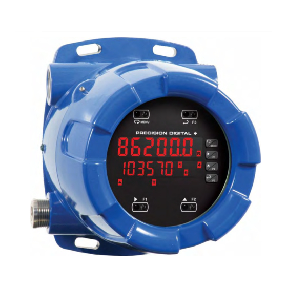
ProtEX-MAX PD8-6200 Explosion-Proof Analog
Input Rate/Totalizer Instruction Manual
• 0-20 mA, 4-20 mA, 0-5 V, 1-5 V, and ±10 V Inputs
• Displays Rate and Total Simultaneously
• Count Up or Down, Total & Grand Total
• Open Chanel Flow with Programmable Exponent
• Non-Resettable Grand Total
• 32-point Linearization
• Modern, Sleek and Practical Enclosure
• Display Mountable at 0°, 90°, 180°, & 270° Degrees
• Explosion-Proof, IP68, NEMA 4X Enclosure
• Isolated 24 VDC @ 25 mA Transmitter Power Supply
• Input Power Options Include 85-265 VAC or 12-24 VDC
• SafeTouch
• Flanges for Wall or Pipe Mounting
• Superluminous Sunlight Readable Display
• Free USB Programming Software & Cable
• 4 Relays + Isolated 4-20 mA Output Option
• USB, RS-232, & RS-485 Serial Communication Options
PRECISION DIGITAL CORPORATION
Find Quality Products Online at:
®
Through-Glass Button Programming
GlobalTestSupply
www.
USB Install
Rate/Totalizer
.com
sales@GlobalTestSupply.com
Advertisement
Table of Contents
Troubleshooting

Subscribe to Our Youtube Channel
Related Manuals for Precision Digital Corporation ProtEX-MAX PD8-6200 Series


Summary of Contents for Precision Digital Corporation ProtEX-MAX PD8-6200 Series
- Page 1 • Superluminous Sunlight Readable Display • Free USB Programming Software & Cable • 4 Relays + Isolated 4-20 mA Output Option • USB, RS-232, & RS-485 Serial Communication Options PRECISION DIGITAL CORPORATION GlobalTestSupply www. .com Find Quality Products Online at:...
- Page 2 Anyone using this product for such applications does so at his/her own risk. Precision Digital Corporation shall not be held liable for damages resulting from such improper use. • Failure to follow installation guidelines could result in death or serious injury.
-
Page 3: Table Of Contents
ProtEX-MAX PD8-6200 Explosion-Proof Analog Input Rate/Totalizer Instruction Manual Table of Contents Table of Contents ----------------------------------------- 3 Scaling the Meter (SCALE) --------------------------- 31 Calibrating the Meter with External Source (Cal) Table of Figures ------------------------------------------- 4 -------------------------------------------------------- 31 Introduction ------------------------------------------------- 4 Time Base, Total Conversion Factor & Total Ordering Information ------------------------------------ 5 Reset ------------------------------------------------ 32 Specifications ---------------------------------------------- 6... -
Page 4: Table Of Figures
ProtEX-MAX PD8-6200 Explosion-Proof Analog Input Rate/Totalizer Instruction Manual Analog Output Programming (AoutPr) --------------- 54 Diagnostics Menu (diag) ---------------------------------- 59 Programmable Function Keys User Menu (user) - 54 Determining Software Version ------------------------- 59 Internal Source Calibration (ICAL) -------------------- 56 Reset Meter to Factory Defaults ------------------------ 59 Meter Operation ----------------------------------------- 57 Factory Defaults &... -
Page 5: Ordering Information
ProtEX-MAX PD8-6200 Explosion-Proof Analog Input Rate/Totalizer Instruction Manual Ordering Information SunBright Display Models 85-265 VAC Model 12-24 VDC Model Options Installed PD8-6200-6H0 PD8-6200-7H0 No options PD8-6200-6H7 PD8-6200-7H7 4 relays & 4-20 mA output WARNING - Cancer and Reproductive Harm - www.P65Warnings.ca.gov Accessories Model Description... -
Page 6: Specifications
ProtEX-MAX PD8-6200 Explosion-Proof Analog Input Rate/Totalizer Instruction Manual Specifications Except where noted all specifications apply to operation at +25°C. Normal Mode General Greater than 60 dB at 50/60 Hz Rejection Display Line 1: 0.6" (15 mm) high, red LEDs Isolation 4 kV input/output-to-power line Line 2: 0.46"... -
Page 7: Rate/Totalizer
ProtEX-MAX PD8-6200 Explosion-Proof Analog Input Rate/Totalizer Instruction Manual Round H Tank Diameter & Length: 999.999 inch or cm Total Reset Via front panel button, external contact calculates volume in gallons or liters closure on digital inputs, automatically via respectively. user selectable preset value and time delay, or through serial communications. -
Page 8: Isolated 4-20 Ma Transmitter Output
ProtEX-MAX PD8-6200 Explosion-Proof Analog Input Rate/Totalizer Instruction Manual Auto When power is applied to the meter, relays Byte-To-Byte 0.01 – 2.54 second Initialization Timeout will reflect the state of the input to the meter. Turn Around Less than 2 ms (fixed) Delay Isolated 4-20 mA Transmitter Output Note: Refer to the P... -
Page 9: Product Ratings And Approvals
ProtEX-MAX PD8-6200 Explosion-Proof Analog Input Rate/Totalizer Instruction Manual Product Ratings and Approvals Enclosure: Type 4X; IP66 Class I, Division 1, Groups B, C, D Class II, Division 1, Groups E, F, G Class III, Division 1, T5/T6 Class I, Zone 1, AEx d, IIC Gb T5/T6 Zone 21, AEx tb IIIC T90°C;... -
Page 10: Compliance Information
ProtEX-MAX PD8-6200 Explosion-Proof Analog Input Rate/Totalizer Instruction Manual Compliance Information Safety UL & c-UL Listed USA & Canada UL 508 Industrial Control Equipment UL File Number E160849 Front Panel UL Type 4X, NEMA 4X, IP65; panel gasket provided Low Voltage EN 61010-1:2010 Directive Safety requirements for measurement, control, and laboratory use... -
Page 11: Safety Information
ProtEX-MAX PD8-6200 Explosion-Proof Analog Input Rate/Totalizer Instruction Manual Safety Information WARNINGS • Read complete instructions prior to installation and operation of the instrument. • Installation and service should be performed only by trained service personnel. Service requiring replacement of internal sub-components must be performed at the factory. •... -
Page 12: Pre-Installed Conduit/Stopping Plug
ProtEX-MAX PD8-6200 Explosion-Proof Analog Input Rate/Totalizer Instruction Manual Pre-Installed Conduit/Stopping Plug The PD8-6200 is supplied with two pre-installed conduit plugs for installations that do not require the use of all conduit entries. The conduit/stopping plugs include an internal 12mm hexagonal socket recess for removal. -
Page 13: Connections
ProtEX-MAX PD8-6200 Explosion-Proof Analog Input Rate/Totalizer Instruction Manual Connections • Static electricity can damage sensitive components. • Observe safe handling precautions for static-sensitive components. • Use proper grounding procedures/codes. • If the instrument is installed in a high voltage environment and a fault or installation error occurs, high voltage may be present on WARNINGS any lead or terminal. -
Page 14: Connectors Labeling
ProtEX-MAX PD8-6200 Explosion-Proof Analog Input Rate/Totalizer Instruction Manual Connectors Labeling The connectors’ label, affixed to the meter, shows the location of all connectors available with requested configuration. Do not connect any equipment other than Precision Digital’s expansion modules, cables, or meters to the RJ45 M-LINK connector. -
Page 15: Figure 5: Transmitter Powered By Internal Supply
ProtEX-MAX PD8-6200 Explosion-Proof Analog Input Rate/Totalizer Instruction Manual Current and Voltage Connections The following figures show examples of current and voltage connections. There are no switches or jumpers to set up for current and voltage inputs. Setup and programming is performed through the front panel buttons. -
Page 16: Serial Communications Connections
ProtEX-MAX PD8-6200 Explosion-Proof Analog Input Rate/Totalizer Instruction Manual Serial Communications Connections The ProtEX-MAX has a 5 position terminal block for connecting RS-485 serial devices. Figure 8 details the wiring connections from the ProtEX-MAX to an RS-485 serial converter (such as the PDA7485 or PDA8485) for a four-wire network. -
Page 17: Figure 10: Rs-485 Wiring
ProtEX-MAX PD8-6200 Explosion-Proof Analog Input Rate/Totalizer Instruction Manual Figure 10: RS-485 Wiring Notes: 1. Termination resistors are optional and values depend on the cable length and characteristic impedance. Consult the cable manufacturer for recommendations. 2. Refer to RS-232 to RS-485 Converter documentation for further details. 3. -
Page 18: Using Pro V U Serial Adapters
ProtEX-MAX PD8-6200 Explosion-Proof Analog Input Rate/Totalizer Instruction Manual Figure 11: RS-485 Two-Wire Multi-Drop Wiring Notes: 1. Termination resistors are optional and values depend on the cable length and characteristic impedance. Consult the cable manufacturer for recommendations. 2. Refer to RS-232 to RS-485 Converter documentation for further details. 3. -
Page 19: Relay Connections
ProtEX-MAX PD8-6200 Explosion-Proof Analog Input Rate/Totalizer Instruction Manual Relay Connections Relay connections are made to two six-terminal connectors labeled RELAY1 – RELAY4 on Figure 3. Each relay’s C terminal is common only to the normally open (NO) and normally closed (NC) contacts of the corresponding relay. -
Page 20: F4 Digital Input Connections
ProtEX-MAX PD8-6200 Explosion-Proof Analog Input Rate/Totalizer Instruction Manual F4 Digital Input Connections A digital input, F4, is standard on the meter. This digital input is connected with a normally open contact across F4 and COM, or with an active low signal applied to F4. Figure 15: F4 Digital Input Connections 4-20 mA Output Connections Connections for the 4-20 mA transmitter output are made to the connector terminals labeled MA OUT. -
Page 21: Digital I/O Connections
ProtEX-MAX PD8-6200 Explosion-Proof Analog Input Rate/Totalizer Instruction Manual Digital I/O Connections The ProtEX-MAX has a 10 position terminal block for connecting digital inputs and outputs. 5 VDC DI 1-4 DO 1-4 Figure 18: Digital I/O Connections The onboard digital inputs (1-4) are configured at the factory to function identically to the front panel pushbuttons (Menu, F1, F2, &... -
Page 22: Setup And Programming
ProtEX-MAX PD8-6200 Explosion-Proof Analog Input Rate/Totalizer Instruction Manual Setup and Programming The meter is factory calibrated prior to shipment to read in milliamps and volts depending on the input selection. The calibration equipment is traceable to NIST standards. Overview There are no jumpers to set for the meter input selection. Setup and programming may be done through the infrared through-glass SafeTouch buttons, or using the mechanical buttons when uncovered. -
Page 23: Front Buttons And Status Led Indicators
ProtEX-MAX PD8-6200 Explosion-Proof Analog Input Rate/Totalizer Instruction Manual Front Buttons and Status LED Indicators Button Description Status Alarm 1 – 8 indicators. Menu Flashing with M Indicates Manual Control Mode Right arrow/F1 Rate indicator Total indicator or Flashing: Up arrow/F2 Tare Enter/F3 Grand Total indicator... -
Page 24: Meterview ® Pro Software
ProtEX-MAX PD8-6200 Explosion-Proof Analog Input Rate/Totalizer Instruction Manual MeterView Pro Software ® The meter can also be programmed using the PC-based MeterView Pro software included with the meter. This software can be installed on any Microsoft® Windows® (XP/Vista/7/8/10) computer by connecting the meter’s onboard USB. -
Page 25: Display Functions And Messages
ProtEX-MAX PD8-6200 Explosion-Proof Analog Input Rate/Totalizer Instruction Manual Display Functions and Messages The meter displays various functions and messages during setup, programming, and operation. The following table shows the main menu functions and messages in the order they appear in the menu. Display Parameter Action/Setting... - Page 26 ProtEX-MAX PD8-6200 Explosion-Proof Analog Input Rate/Totalizer Instruction Manual Display Parameter Action/Setting Display Parameter Action/Setting Latching- Set relay for latching Lt-CLr Display 2 Program display 2 value Dis 2 cleared operation with manual Output 2 Program output 2 value Out 2 reset only after alarm (e.g.
-
Page 27: Main Menu
ProtEX-MAX PD8-6200 Explosion-Proof Analog Input Rate/Totalizer Instruction Manual Main Menu The main menu consists of the most commonly used functions: Reset, Control, Setup, and Password. • Press Menu button to enter Programming Mode, then press the Up arrow button to scroll main menu. -
Page 28: Setting Up The Rate/Totalizer Meter (Setup)
ProtEX-MAX PD8-6200 Explosion-Proof Analog Input Rate/Totalizer Instruction Manual Setting Up the Rate/Totalizer Meter (setup) The Setup menu is used to select: 1. Input signal the meter will accept and enable totalizer features 2. Select the display units/tags 3. Select the decimal point position 4. -
Page 29: Setting The Input Units Or Custom Tags (Units)
ProtEX-MAX PD8-6200 Explosion-Proof Analog Input Rate/Totalizer Instruction Manual Setting the Input Units or Custom Tags (units) Enter the input unit or custom tag that will be displayed if alternating rate, total, or grand total and units is selected in the units menu, or d unit is selected as the line 2 parameter. See the flow chart on page 33 to access the display menu to show the unit or tag on line 2. -
Page 30: Programming The Rate/Totalizer (Prog)
ProtEX-MAX PD8-6200 Explosion-Proof Analog Input Rate/Totalizer Instruction Manual Programming the Rate/Totalizer (prog) It is very important to read the following information, before proceeding to program the meter: • The meter is factory calibrated prior to shipment to read in milliamps and volts depending on the input selection. -
Page 31: Scaling The Meter (Scale)
ProtEX-MAX PD8-6200 Explosion-Proof Analog Input Rate/Totalizer Instruction Manual Scaling the Meter (SCALE) The process inputs (4-20 mA and 10 VDC) can be scaled to display the process variable in engineering units. A signal source is not needed to scale the meter; simply program the inputs and corresponding display values. -
Page 32: Time Base, Total Conversion Factor & Total Reset
ProtEX-MAX PD8-6200 Explosion-Proof Analog Input Rate/Totalizer Instruction Manual Time Base, Total Conversion Factor & Total Reset The time base, total conversion factor, and total reset menus are located in the Program menu. The total and grand total have their own independent settings. This means that one can be displaying the value in gallons while the other displays in million gallons, liters, m , etc. -
Page 33: Setting The Display Parameter & Intensity (Dsplay)
ProtEX-MAX PD8-6200 Explosion-Proof Analog Input Rate/Totalizer Instruction Manual Setting the Display Parameter & Intensity (dsplay) Display line 1 can be programmed to display: 1. Rate value 2. Total or grand total 3. Toggle rate/total 4. Toggle rate/G-total 5. Relay set points 6. -
Page 34: Setting The Relay Operation (Relay)
ProtEX-MAX PD8-6200 Explosion-Proof Analog Input Rate/Totalizer Instruction Manual Setting the Relay Operation (relay) This menu is used to set up the operation of the relays. During setup, the relays do not follow the input and they will remain in the state found prior to entering the Relay menu. -
Page 35: Relay Assignment (Assign)
ProtEX-MAX PD8-6200 Explosion-Proof Analog Input Rate/Totalizer Instruction Manual Relay Assignment (Assign) The relays can be assigned to any of the following parameters: 1. Rate for low or high alarm indication 2. Total for alarm indication 3. Grand total for alarm indication 4. -
Page 36: Programming Set And Reset Points
ProtEX-MAX PD8-6200 Explosion-Proof Analog Input Rate/Totalizer Instruction Manual Programming Set and Reset Points High alarm indication: program set point above reset point. Low alarm indication: program set point below reset point. The deadband is determined by the difference between set and reset points. Minimum deadband is one display count. -
Page 37: Relay And Alarm Operation Diagrams
ProtEX-MAX PD8-6200 Explosion-Proof Analog Input Rate/Totalizer Instruction Manual Relay and Alarm Operation Diagrams The following graphs illustrate the operation of the relays, status LEDs, and ACK button. High Alarm Operation (Set > Reset) Low Alarm Operation (Set < Reset) For Manual reset mode, ACK can be pressed anytime to turn "off" relay. To detect a new alarm condition, the signal must go below the set point, and then go above it. -
Page 38: Pump Alternation Control Operation
ProtEX-MAX PD8-6200 Explosion-Proof Analog Input Rate/Totalizer Instruction Manual Pump Alternation Control Operation Rate Relay Sampling Operation Input Reset Sample Sample Sample Time Time Time Relay When the signal crosses the set point, the relay trips and the sample time starts. After the sample time has elapsed, the relay resets. -
Page 39: Signal Loss Or Loop Break Relay Operation
ProtEX-MAX PD8-6200 Explosion-Proof Analog Input Rate/Totalizer Instruction Manual Signal Loss or Loop Break Relay Operation The following graph shows the loop break operation for a high alarm relay. Input Reset de-energized energized Relay Loop Break = Ignore Relay Loop Break = Off Relay Loop Break = On When the meter detects a break in the 4-20 mA loop, the relay will go to one of the following selected... -
Page 40: Relay Operation Details
ProtEX-MAX PD8-6200 Explosion-Proof Analog Input Rate/Totalizer Instruction Manual Relay Operation Details Overview The relay capabilities of the meter expand its usefulness beyond simple indication to provide users with alarm and control functions. These capabilities include front panel alarm status LEDs as well as either 2 or 4 optional internal relays. -
Page 41: Latching And Non-Latching Relay Operation
ProtEX-MAX PD8-6200 Explosion-Proof Analog Input Rate/Totalizer Instruction Manual Latching and Non-Latching Relay Operation The relays can be set up for latching (manual reset) or Relay terminology for following tables non-latching (automatic reset) operation. Terminology Relay Condition Alarm (Tripped) The On and Off terminology does not refer to the status of Normal (Reset) the relay’s coil, which depends on the fail-safe mode Acknowledged... -
Page 42: Acknowledging Relays
ProtEX-MAX PD8-6200 Explosion-Proof Analog Input Rate/Totalizer Instruction Manual Acknowledging Relays There are two ways to acknowledge relays programmed for manual reset: 1. Via the programmable front panel function keys F1-F3 (Default: F3 assigned to ACK). 2. Remotely via a normally open pushbutton wired across one of the digital inputs and the +5 V terminals on the digital I/O modules, or using the F4 digital input, which is triggered with a contact closure to COM, or with an active low signal (see page 20). - Page 43 ProtEX-MAX PD8-6200 Explosion-Proof Analog Input Rate/Totalizer Instruction Manual Application #2: Pump Alternation Using Relays 3 & 4 1. Relays 1 and 2 are set up for low and high alarm indication. 2. Relays 3 and 4 are set up for pump alternation. Set and Reset Point Programming Relay Set Point...
-
Page 44: Setting Up The Interlock Relay (Force On) Feature
ProtEX-MAX PD8-6200 Explosion-Proof Analog Input Rate/Totalizer Instruction Manual Setting Up the Interlock Relay (Force On) Feature Relays 1-4 can be set up as interlock relays. To set up the relays for the interlock feature: 1. Access the Setup – Relay – Action menu and set the action to off. 2. -
Page 45: Scaling The 4-20 Ma Analog Output (Aout)
ProtEX-MAX PD8-6200 Explosion-Proof Analog Input Rate/Totalizer Instruction Manual Scaling the 4-20 mA Analog Output (Aout) The 4-20 mA analog output can be scaled to provide a 4-20 mA signal for any display range selected. No equipment is needed to scale the analog output; simply program the display values to the corresponding mA output signal. -
Page 46: Setting Up The Password (Pass)
ProtEX-MAX PD8-6200 Explosion-Proof Analog Input Rate/Totalizer Instruction Manual Setting Up the Password (pass) The Password menu is used for programming three levels of security to prevent unauthorized changes to the programmed parameter settings and to program the non-resettable totalizer. Pass 1: Allows use of function keys and digital inputs Pass 2: Allows use of function keys, digital inputs and editing set/reset points Pass 3: Restricts all programming, function keys, and digital inputs. -
Page 47: Making Changes To A Password Protected Meter
ProtEX-MAX PD8-6200 Explosion-Proof Analog Input Rate/Totalizer Instruction Manual Making Changes to a Password Protected Meter If the meter is password protected, the meter will display the message Locd (Locked) when the Menu button is pressed. Press the Enter button while the message is being displayed and enter the correct password to gain access the menu. -
Page 48: Advanced Features Menu
ProtEX-MAX PD8-6200 Explosion-Proof Analog Input Rate/Totalizer Instruction Manual Advanced Features Menu To simplify the setup process, functions not needed for most applications are located in the Advanced Features menu. Press and hold the Menu button for three seconds to access the advanced features of the meter. Advanced Features Menu &... -
Page 49: Noise Filter (Filter)
ProtEX-MAX PD8-6200 Explosion-Proof Analog Input Rate/Totalizer Instruction Manual Display Parameter Action/Setting Display Parameter Action/Setting Analog output Program analog output F3 function Assign F3 function key AoutPr programming parameters Select source for the 4- Assign F4 function Source F4 function Source 20 mA output (digital input) Overrange... -
Page 50: Rounding Feature (Round)
ProtEX-MAX PD8-6200 Explosion-Proof Analog Input Rate/Totalizer Instruction Manual Rounding Feature (round) The rounding feature is used to give the user a steadier display with fluctuating signals. Rounding is used in addition to the filter function. Rounding causes the display to round to the nearest value according the rounding selected. See examples below: Rounding Actual... -
Page 51: Serial Communications Overview
ProtEX-MAX PD8-6200 Explosion-Proof Analog Input Rate/Totalizer Instruction Manual Serial Communications Overview RS-232 and RS-485 are standard interfaces approved by the Electronic Industries Alliance (EIA) for connecting serial devices. In EIA terms, the device (e.g. meter) that connects to the interface is called a Data Communications Equipment (DCE) and the device to which it connects (e.g. -
Page 52: Select Menu (Select)
ProtEX-MAX PD8-6200 Explosion-Proof Analog Input Rate/Totalizer Instruction Manual Select Menu (SElEct) The Select menu is used to select the signal input conditioner applied to the input (linear, square root, programmable exponent, or round horizontal tank), low-flow cutoff, and analog output programming. The multi-point linearization is part of the linear function selection. -
Page 53: Low-Flow Cutoff (Cutoff)
ProtEX-MAX PD8-6200 Explosion-Proof Analog Input Rate/Totalizer Instruction Manual Round Horizontal Tank Linearization (rHt) This function automatically calculates the volume in a round horizontal tank with flat ends. This function is only used when Total is set to no. Set the display for the desired decimal point and engineering units before entering the round horizontal tank function. -
Page 54: Analog Output Programming (Aoutpr)
ProtEX-MAX PD8-6200 Explosion-Proof Analog Input Rate/Totalizer Instruction Manual Analog Output Programming (AoutPr) The Analog Output Programming menu is used to program the behavior of the 4-20 mA output. The following parameters and functions are programmed in this menu: 1. Source: Source for generating the 4-20 mA output (e.g. PV) 2. - Page 55 ProtEX-MAX PD8-6200 Explosion-Proof Analog Input Rate/Totalizer Instruction Manual Function Keys & Digital I/O Available Settings Refer to the following table for descriptions of each available function key or digital I/O setting. Display Description Display Description Force relay 1 (*through 4) into the Directly access the relay menu relay F On 1*...
-
Page 56: Internal Source Calibration (Ical)
ProtEX-MAX PD8-6200 Explosion-Proof Analog Input Rate/Totalizer Instruction Manual Internal Source Calibration (ICAL) The meter is factory calibrated prior to shipment to read in milliamps and volts, depending on the input selection. The calibration equipment is traceable to NIST standards. The use of calibrated signal sources is necessary to calibrate the internal source of the meter. The meter’s internal source is what allows the user to scale the meter without applying a signal. -
Page 57: Meter Operation
ProtEX-MAX PD8-6200 Explosion-Proof Analog Input Rate/Totalizer Instruction Manual Meter Operation The meter is capable of accepting current (0-20 mA, 4-20 mA) and voltage signals (0-5 V, 1-5 V, 0-10 V, 10 V) and displaying these signals in engineering units from -99999 to 999999 (e.g. a 4-20 mA signal could be displayed as -50.000 to 50.000). -
Page 58: F4 Operation
ProtEX-MAX PD8-6200 Explosion-Proof Analog Input Rate/Totalizer Instruction Manual F4 Operation A digital input, F4, is standard on the meter. This digital input is programmed identically to function keys F1, F2, and F3. The input is triggered with a contact closure to COM, or with an active low signal. During operation, F4 operates according to the way it has been programmed in the Advanced Features –... -
Page 59: Troubleshooting
ProtEX-MAX PD8-6200 Explosion-Proof Analog Input Rate/Totalizer Instruction Manual Troubleshooting Due to the many features and functions of the meter, it’s possible that the setup of the meter does not agree with what an operator expects to see. If the meter is not working as expected, refer to the Diagnostics menu and recommendations below. Diagnostics Menu (diag) The Diagnostics menu is located in the Advanced Features menu, to access Diagnostics menu see Advanced Features Menu, page 48. -
Page 60: Factory Defaults & User Settings
ProtEX-MAX PD8-6200 Explosion-Proof Analog Input Rate/Totalizer Instruction Manual Factory Defaults & User Settings The following table shows the factory setting for most parameters. Parameter Display Default Setting Parameter Display Default Setting Relay 4 Input type 4-20 mA Input Rate Asign4 assignment Total total... -
Page 61: Troubleshooting Tips
ProtEX-MAX PD8-6200 Explosion-Proof Analog Input Rate/Totalizer Instruction Manual Parameter Display Default Setting Parameter Display Default Setting Password 1 000000 (unlocked) Total password 000000 (unlocked) Pass 1 Total Grand total Password 2 000000 (unlocked) Pass 2 000000 (unlocked) Gtotal password Password 3 000000 (unlocked) Pass 3 Troubleshooting Tips... -
Page 62: Service
ProtEX-MAX PD8-6200 Explosion-Proof Analog Input Rate/Totalizer Instruction Manual Symptom Check/Action Check: Relay operation is reversed Fail-safe in Setup menu Wiring of relay contacts Check: Relay and status LED do not Relay action in Setup menu respond to signal Set and reset points Relays in manual control mode or relay interlock switches opened. -
Page 63: Mounting Dimensions
ProtEX-MAX PD8-6200 Explosion-Proof Analog Input Rate/Totalizer Instruction Manual Mounting Dimensions All units: inches (mm) Figure 22: Enclosure Dimensions – Front Figure 23: Enclosure Dimensions – Side View Cross Section View GlobalTestSupply www. .com Find Quality Products Online at: sales@GlobalTestSupply.com... - Page 64 ProtEX-MAX PD8-6200 Explosion-Proof Analog Input Rate/Totalizer Instruction Manual This Page Intentionally Left Blank GlobalTestSupply www. .com Find Quality Products Online at: sales@GlobalTestSupply.com...
-
Page 65: Eu Declaration Of Conformity
SIRA 10 ATEX M462 ATEX Notified Body for Quality Assurance: Sira Certification Service, NB 0518 Unit 6, Hawarden Industrial Park Hawarden, Deeside, CH5 3US, UK Signed for and on behalf of Precision Digital Corporation: Name: Jeffrey Peters Company: Precision Digital Corporation... - Page 66 ProtEX-MAX PD8-6200 Explosion-Proof Analog Input Rate/Totalizer Instruction Manual PRECISION DIGITAL CORPORATION LIM8-6200_D SFT039 Ver 4.010 & up 12/18 GlobalTestSupply www. .com Find Quality Products Online at: sales@GlobalTestSupply.com...
Need help?
Do you have a question about the ProtEX-MAX PD8-6200 Series and is the answer not in the manual?
Questions and answers