
Related Manuals for Amplitec C23S Series


Summary of Contents for Amplitec C23S Series
- Page 1 C23S Series Signal Repeater User Manual PLEASE KEEP APPROPRIATELY AND CAREFULLY READ THIS USER MANUAL BEFORE INSTALLATION...
-
Page 2: Table Of Contents
Ensure of grounding, waterproof and The power supply voltage of the repeater lightning protection when installing the should meet the standards of security repeater. requirements. The user had better not dismantle the The repeater should be installed and repeater to maintain or replace the initiated by professionals. -
Page 3: Package Contents
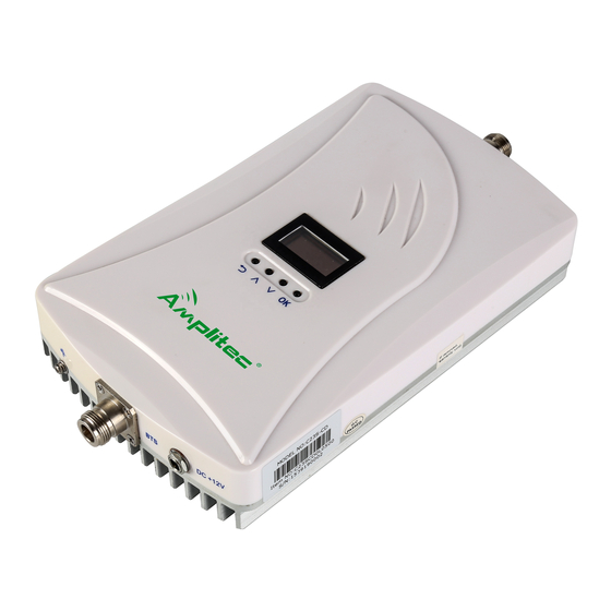
U-shape back holder Product Description Amplitec C23S dual band series repeater adopts anti-interference, digital ALC, baseband synch and GPS synch technologies, supporting built-in or external antenna. This model is equipped with LCD screen, to clearly display parameters and working status like the working frequency, gain, output power, ISO and ALC alarms. -
Page 4: Operation And Display Description
A : Donor antenna port (N-female) B : Service antenna port(N-female) C : 12V DC power supply port D : Grounding screw E : Display screen F : Return button G : Upward button ... - Page 5 customized as clients require.). It will scroll the working frequency, downlink input and output signal, gain and alarm on the screen. (As Figure 1) Figure 1 c. View the Working Frequency Bands Press UP or DOWN button to move the cursor to the first line(as Figure 2). Then press OK button to check the working frequency(Figure 3).
- Page 6 e. View the Gain Move the cursor to the third line “ GAIN” with UP or DOWN button (as Figure 6) from the home page, and press OK button to view the real-time gain (as Figure 7). Press the RETURN button back to the home page.
- Page 7 Then move the cursor to the third line “Gain ” with UP or DOWN button (as Figure 11), press OK to enter the ATT setting interface, then select one system, press OK button(as Figure 12). Figure 11 Figure 12 To increase or decrease the gain value, please press the UP or DOWN button (as Figure 13 and 14);...
- Page 8 Then press OK to view, select AGC (as Figure17), press OK to view AGC alarm (as Figure18). Figure 17 Figure 18 Select DL OUTPUT (as Figure 19), press OK button to view DL OUTPUT alarm (as Figure 20). Figure 19 Figure 20 To remove alarm, if it is in smart mode, the device will make adjustment automatically after re-powering;...
-
Page 9: Technical Specification
After factory default, it will detect isolation automatically. To view ISO, move the cursor to the forth line “STATUS”, press OK button, and select “ISOLATION” (as Figure 23), then press OK button to view ISO (as Figure 24). After that, press the RETURN button back to home page. Figure 23 Figure 24 Technical Specification... -
Page 10: Installation Guides
Installation Guides Installation Requirements 1) With Stable and independent power supply. 2) The repeater should be installed in the space without corrosive gas, smokes and leaky liquids. 3) The repeater should be installed on the wall that is ventilated, waterproof, lightning-proof and without sunshine. -
Page 11: Antenna Connection
3) Put the expansion plug(size: 8mm) into the 4 drilled holes. 4) As shown in the figure, align the fixing holes of the U-shaped back holder with corresponding holes on the wall. Then drive 4 pcs of M6*40 screws into the expand plugs with screwdriver. Finally, hang the repeater firmly on the U-shaped back holder. -
Page 12: Starting
Starting 1) If possible, please wire up the grounding screw of the repeater to the ground wire of the power line. 2) Make sure the feeder cables between repeater and antennas are firmly connected. 3) Connect the DC plug of the 5V/2A power adapter to the DC+5V port of the repeater. Then put AC plug connecting to the nearby 220V power outlet. - Page 13 Manufacturer: Foshan Amplitec Tech Development Co.,Ltd Addr: 4th Floor, 4th Building, No. 60 of Langbao West Rd, Zhangcha Foshan, China,528000 Tel:0757-83308238,Fax:0757-83123923 Email:info@amplitec.cn, Website:www.amplitec.net...
Need help?
Do you have a question about the C23S Series and is the answer not in the manual?
Questions and answers