
Related Manuals for Amplitec C23S-EGSM


Summary of Contents for Amplitec C23S-EGSM
- Page 1 23dBm Single Wide Band Repeater C23S-EGSM User Manual Notes: Thank you for purchasing our product. Please read carefully the manual before installation...
-
Page 2: Chapter 1 - Safety Warning
Chapter 1 - Safety Warning Users must follow the below principles: Repeater should follow system requirement communication equipment, assure good groundings and lightning protection. The power supply voltage of repeater should meet the standards security requirement; repeater-operator can operate only after cutting power in advance. -
Page 3: Chapter 2 - Summary
Chapter 2 - Summary In mobile communication, it is inevitable that macro-cell coverage cannot cover weak or dead zones; to use repeater is a good choice in these areas. These band selective repeaters mainly applied in covering small blind and weak zones. -
Page 4: Chapter 3 - Standard And Specification
Chapter 3 - Standard and Specification 3.1 Product description Repeater is essentially a same frequency, transparent and amplify equipment. Inside the single system repeater there are two independent amplify link roads---Up Link and Down Link. DL gets the RF signal by donor antenna from the BTS, amplifies the signal and then transmits to the area to be covered through the coverage antenna. -
Page 5: System Schematic
3.3 System Schematic Figure 3.3.1 the Schematic of the repeater 3.4 Electric Specifications Items Uplink Downlink Frequency Range 880 ~ 915 MHz 925 ~ 960 MHz Output Power(CW) 23±2 dBm 23±2 dBm Gain 73±2 dB 73±2 dB Ripple ≤15 dB ≤15 dB Noise Figure @ max. -
Page 6: Machine Specifications
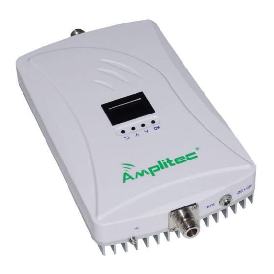
Items Uplink Downlink 9KHz~1GHz ≤-36 dBm ≤-36 dBm Spurious Emission ≤-30 dBm ≤-30 dBm 1GHz~12.75GHz Time Delay ≤0.5 μs ≤0.5 μs Power Supply DC:12V Power Consumption < 15W RF Connector N-Female Environment Conditions IP40 Humidity < 90% Operating Temperature -10℃ ~ +55℃ 3.5 Machine Specifications RF Connector N-Female... - Page 7 3.6 Appearance and function keys Figure 3.6.1 repeater display, control panel and ports...
-
Page 8: Function Key Operation
A : Donor antenna port (N-female) B : Coverage antenna port(N-female) C :12V DC power supply port D : Return button E : Up button F : Down button G : OK button ... - Page 9 To view the working frequencies Move the cursor to the first line with up or down button (as shown in Figure 3.7.3.1), and press OK button to enter the working frequencies display interface (as shown in Figure 3.7.3.2). Press the return button back to the main menu.
- Page 10 Press OK to enter, “SMART” is on the left and “MANUAL” is on the right, select “MANUAL” with up or down button and press OK (as shown in Figure 3.7.6.3). Figure 3.7.6.3 Then move the cursor to the third line “Gain ” with up or down button (as shown in Figure 3.7.6.4), press OK to enter the ATT setting interface, then select one system, press OK(as shown in Figure 3.7.6.5).
- Page 11 Figure 3.7.6.6 Figure 3.7.6.7 View Alarm. Move the cursor to the forth line “STATUS” from main menu, then press OK to enter (as shown in Figure 3.7.7.1), then navigate the cursor to “ ALARM ITEMS” with up or down button (as shown in Figure 3.7.7.2). Figure 3.7.7.1 Figure 3.7.7.2 Then press Ok to view, select AGC (as shown in Figure 3.7.7.3), press OK to...
- Page 12 Select DL OUTPUT (as shown in Figure 3.7.7.5), press OK to view DL OUTPUT alarm (as shown in Figure 3.7.7.6). Figure 3.7.7.5 Figure 3.7.7.6 To remove alarm, if it is in Smart mode, the device will make adjustment automatically after re-powering; if it is in Manual mode, you should adjust the outdoor antenna and the gain manually.
- Page 13 After restoring to factory setting, it will detect ISO automatically. To view ISO, move the cursor to the forth line “STATUS”, press OK, and select “ISOLATION” (as shown in Figure 3.7.8.3), then press OK to view ISO (as shown in Figure 3.7.8.4).
-
Page 14: Chapter 4 Installation
Chapter 4 Installation 4.1 Installation requirements Before install or operate this repeater, please read the first chapter “safety instructions” carefully. Please make sure the grounding wire is firmly grounded and the power cord is firmly connected before power on the device. ... - Page 15 Select a proper installation site according to the size and installation requirements of the repeater. Drill holes with percussion drill according to the position of the shell holes, pore size isΦ7 and the hole location is as follows(unit: mm). Mounting Hole Dimensions Put theΦ8 expand plug into the 4 holes.
-
Page 16: External Connections
4.3 External connections Repeater Ports Ports of the repeater are shown in Figure 4.3.1. Please do not power on the repeater until the feeder is connected. The installation of antenna should be designed and conducted by professional personnel. When connecting feeder, please wrap the interface with waterproof tape to prevent water into the repeater. - Page 17 range 100~240V, frequency range 50~60Hz. Output DC is 12V 2A. GND:grounding. 4.4 Start the Repeater Figure 4.4 repeater display and its control panel After ensuring that the repeater is installed properly, that power supply and GND meet the requirements, turn on the repeater. After 5 seconds, repeater initialization is completed and it enters the normal working state.
-
Page 18: Chapter 5 Maintenance
Chapter 5 Maintenance 5.1 Operation and maintenance Power supply Please make sure the voltage and frequency of AC power is in conformity with that of the repeater. Component replacement Please do not maintain or replace the components by yourself, in case you may get an electric shock.
Need help?
Do you have a question about the C23S-EGSM and is the answer not in the manual?
Questions and answers