Advertisement
Applied Machines: 235/215/195
MFP: 23 ppm/21 ppm/19 ppm
Product Code: A3PE/A3R2
I. Accessory parts
No.
Name
1. Tray label/
Paper size
label
2. Screw A
(4 × 12 mm)
3. Screw B
(3 × 8 mm)
4. Installation
manual
After unpacking, be sure to get rid of the
packaging materials and keep them out of
the reach of children.
Putting the head in the plastic bag
involves danger of suffocation.
Note:
This manual provides the illustrations of the acces-
sory parts and machine that may be slightly differ-
ent in shape from yours. In that case, instead of
the illustrations, use the appearance of your
machine to follow the installation procedure. This
does not cause any significant change or problem
with the procedure.
1BS0832701
PF-507
INSTALLATION MANUAL
Shape
Q'ty
1
set
4
9738
1
9646
1
set
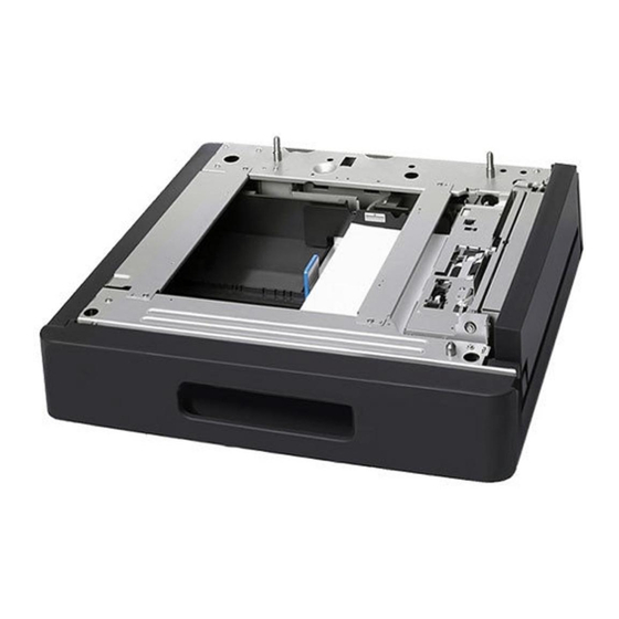
4980IXC019DA
Paper Feeder Unit
II. Installation procedures
Note:
When the paper feeder unit(s) is installed in the
machine, perform steps 1 to 4 below and then per-
form steps 5 to 9 in <Installation of one paper
feeder unit to another> described on page E-3.
1. Turn off the machine and unplug the power cord
from the power outlet.
2. Remove the protective tape and cushioning
materials.
3. Remove the rear cover of the paper feeder unit.
(One screw)
Rear cover
E-1
A3PFIXC009DA
A3PFIXC010DA
A3PF-9950-00
Advertisement
Table of Contents

Related Manuals for Develop PF-507

Summary of Contents for Develop PF-507
- Page 1 PF-507 Paper Feeder Unit INSTALLATION MANUAL Applied Machines: 235/215/195 MFP: 23 ppm/21 ppm/19 ppm Product Code: A3PE/A3R2 I. Accessory parts II. Installation procedures Name Shape Q’ty Note: When the paper feeder unit(s) is installed in the 1. Tray label/ machine, perform steps 1 to 4 below and then per- Paper size form steps 5 to 9 in <Installation of one paper...
- Page 2 <Installation to the machine> 5. Slide out the drawers of the machine and the paper feeder unit and secure the paper feeder Note: unit by tightening the two screws at the front. When adding multiple paper feeder units to the (Two supplied screws A) machine, see <Installation of one paper feeder unit to another>...
- Page 3 7. Connect the ground wire of the paper feeder unit <Installation of one paper feeder unit to another> to the machine. (One supplied screw B) 4. Mount one paper feeder unit to another as shown 8. Plug the connector of the paper feeder unit into in the illustration.
- Page 4 III. Loading the paper feeder unit with 6. Secure the paper feeder units together in the rear. (Two supplied screws A) paper 1. Slide out the drawer of the lower paper feeder unit and press down the paper lifting plate until it locks in position.
- Page 5 IV. Paper feed check (3) Make a paper feed check again and confirm that paper is fed without problem. 1. Plug the power cord into the power outlet and (4) Reinstall the rear cover. (11 screws) turn on the machine. Note: 2.
- Page 6 11. Measure dimension A of the test print. If dimension A is less than the specified range, move Specifications the guide plate in the direction of the arrow. : 20 ± 2.0 mm Letter : 11.2 ± 2.0 mm Exit direction A3PFIXC023DA 14.
Need help?
Do you have a question about the PF-507 and is the answer not in the manual?
Questions and answers