Advertisement
Quick Links
CHAPTER 1.
CHAPTER 2.
CHAPTER 3. TROUBLE SHOOTING ............................................................ 11
CHAPTER 4. WAVE FORM ........................................................................... 15
CHAPTER 5. BLOCK DIAGRAM ................................................................... 24
CHAPTER 6. CIRCUIT DIAGRAM ................................................................. 25
CHAPTER 7. PARTS LAYOUT ...................................................................... 37
Parts marked with "
" are important for maintaining the safety of the set. Be sure to replace these parts with specified
ones for maintaining the safety and performance of the set.
SERVICE MANUAL
MODEL
CONTENTS
SHARP CORPORATION
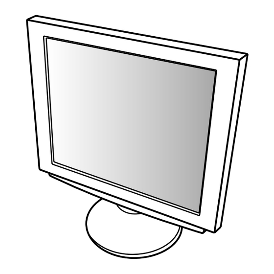
LCD COLOR MONITOR
LL-T1810A
............ 4
This document has been published to be used
for after sales service only.
The contents are subject to change without notice.
.......... 1
Advertisement

Related Manuals for Sharp LL-T1810A


Summary of Contents for Sharp LL-T1810A
- Page 1 SERVICE MANUAL LCD COLOR MONITOR LL-T1810A MODEL CONTENTS CHAPTER 1... 1 CHAPTER 2..... 4 CHAPTER 3. TROUBLE SHOOTING ............11 CHAPTER 4. WAVE FORM ................15 CHAPTER 5. BLOCK DIAGRAM ..............24 CHAPTER 6. CIRCUIT DIAGRAM ..............25 CHAPTER 7.
- Page 2 Symbol/PartsCod) - - - - - - - - - - - - - - - - - - - - - - - - - - - - - - - - - - - - - - - - - - - - - - - - - - - - - - - CHAPTER 1.
- Page 3 2. Technical specifications Item Unit Power supply voltage 11.4 12.0 13.2 Working temperature range — °C Storing temperature range — °C Humidity range — Visual angle range Vertical (CR — Temperature Horizontal (CR — Temperature Contrast ratio(CR) (θ = 0°) —...
- Page 4 NOMENCLATURE AND FUNCTION Front view Note: Never block the ventilation Front view openings as this may lead to Ventilation overheating inside the monitor openings and result in malfunction. Power terminal Remove the cover to see the power terminal. The AC adapter is connected here. INPUT 2 terminal and USB port Remove the cover to view the computer input terminal (INPUT 2) and USB port.
- Page 5 CHAPTER 2. CONNECTION, ADJUSTMENT, OPERATION, AND FUNCTIONS 5. Connect power cord to AC adapter. [1] CONNECTION, POWER ON/OFF CONNECTING THE MONITOR TO A POWER SOURCE Use only the AC adapter supplied. 1. Remove the stand cover. Power cord (Rear View) Stand cover Lift one side Fitting the AC adapter inside the stand...
- Page 6 CONNECTING THE MONITOR TO A COMPUTER CONNECTING A USB DEVICE (PC etc.) This monitor can be used with hubs which use the USB standard (Rev. 1.1). When connecting, ensure that both the monitor and computer are switched off. Downstream (2 ports) USB devices such as keyboard and mouse can be connected here.
- Page 7 The power LED [2] INSTRUCTIONS FOR ATTACHING A VESA COMPLIANT ARM An arm or stand based on the VESA standard (purchased separately) can be attached to the monitor. Procurement of the arm or stand is at the customer’s discretion. Arms or stands able to be used Attachments must satisfy the following.
- Page 8 ■Adjustment lock function 6. Attach the arm to the monitor with the four screws. By disabling the control buttons (i.e. setting the lock) any attempted changes to adjusted values will be voided. 1. Turn off the monitor power. 2. While pressing the MENU button, press the power button (i.e. turn the power on).
- Page 9 MANUAL SCREEN ADJUSTMENT Adjustment pattern Fine adjustments can be made using the On Screen Display (OSD) Menu provided. MENU 1: ADJUSTMENT CLOCK, PHASE, H-POS (horizontal positioning) and V- POS (vertical positioning) MENU 2: GAIN CONTROL BRIGHT (brightness), CONT (contrast) MENU 3: WHITE BALANCE •...
- Page 10 CLOCK BRIGHT (brightness) Total screen brightness can be adjusted while watching the color The figure below demonstrates how to adjust so that vertical flicker pattern. ( buttons) noise is not emitted. ( buttons) Color pattern Vertical flicker noise CONT (Contrast) PHASE While watching the color pattern, adjustments can be made so that all The figure below demonstrates how to adjust so that horizontal flicker...
- Page 11 INPUT (Input mode) Display mode Hsync Vsync The input mode can be set ( buttons) frequency VESA: VESA mode Power 640 x 480 35.0kHz 66.7Hz 30.2MHz Macintosh MAC: Power Macintosh mode 832 x 624 49.7kHz 74.6Hz 57.3MHz series 400 LINES (degree of resolution) 1024 x 768 60.2kHz 75.0Hz...
- Page 12 CHAPTER 3. TROUBLE SHOOTING Check and remedy any failure according to the following procedure. LED color changes in color from orange to <An error occurs when green by pressing power switch? synchronous signal is detected.> LED comes on in orange soon after RGB <...
- Page 13 Continued from the preceding page. IC34 No. 51 pins signal output is at H level Check the microprocessor control circuits (DC+5V)? around IC29 and IC34. IC34 No. 52 pins signal output is at L level Check the microprocessor control circuits (0V)? around IC29 and IC34.
- Page 14 <Screen is not normal > Check DC+5V power supply line (VCC and Test terminal TP3 shows DC+5V? ADVCC) and power supply circuit around IC5. Check DC+5V power supply line for PLL IC25 No. 1 pin shows DC+5V? and power supply circuit around the IC24. Check DC+3.3V power supply line (LVCC) Test terminal TP5 shows DC+3.3V? and power supply circuit around IC7.
- Page 15 Continued from the preceding page. Adjustment items of “GAIN CONTROL” and Adjust and set screen according to the LCD screen color is abnormal? “WHITE BALANCE” are set correctly? LCD screen setting procedure. Analog color signal outputs of IC 14 Nos. 25, 27, 30 and Check video switch circuit around IC14.
- Page 16 CHAPTER 4. WAVE FORM 1. WAVE FORM DESCRIPTION Waveform measurement condition: Input each of the display patterns and measure the waveform (timing chart). Wave-form Measurement point Name of waveform Display pattern 22 pin of the IC34 Arbitrary 9 pin, 18 pin of the IC14 VSYNC Arbitrary 8 pin, 17 pin of the IC14...
- Page 17 WAVE FORM 1 : XIN (22 pin of the IC34) WAVE FORM 4 : MPU VSY (6 pin of the IC34) Frequency 7.987MHz Frequency 75Hz Display Screen : arbitrary Display Screen : arbitrary WAVE FORM 2 : VSYNC (9 pin, 18th pin of the IC14) WAVE FORM 5 : MPU HSY (7 pin of the IC34) Frequency 75Hz Frequency 80kHz...
- Page 18 WAVE FORM 7 : LCDDEA, DEB (FL2, FL5) WAVE FORM 10 : SOGOUT (25 pin of the IC14) Frequency 70kHz Display Screen : 16 monochromatic gradation patterns Display Screen : arbitrary WAVE FORM 11 : VSwitch RGB OUT (27 pin , 30 pin and 35 pin of the IC14) WAVE FORM 8 : DSYNC (24 pin of the IC25) Display Screen : 16 monochromatic gradation patterns...
- Page 19 WAVE FORM 13 : A/D OUT DATA WAVE FORM 15 : ASIC OUT DATA (156 ~ 163 pins, 166 ~ 174 pins, 177 ~ 183 pins, 191 ~ 204 pins, 207 ~ 216 pins of the IC27) Display Screen : Monochrome pattern at every 2 lines Display Screen : Monochrome pattern at every 2 lines WAVE FORM 14 : ASIC IN DATA WAVE FORM 16 : ASIC IN/OUT DATA...
- Page 20 WAVE FORM 17 : OSD COLOR DATA 2. CIRCUIT DIAGRAM (13, 15, 17 pins of IC31) Main board (Ver.7) Display Screen : All black pattern OSD menu display Sheet No. Description RGB signal input Synchronizing separator A/D converter and PLL circuit ASIC circuit SGRAM circuit Microprocessor...
- Page 21 IC terminal diagram (1/3)
- Page 22 IC terminal diagram (2/3)
- Page 23 IC terminal diagram (3/3)
- Page 24 3. Wiring diagram This drawing shows a basic circuit. The actual wiring might be somewhat different from this drawing. • Circuit diagram (Main PWB, Control PWB, Jack PWB, D-sub PWB) 1. Resistance indications [Resistance] • No indication - - - - - Ω, k - - - - - kΩ, M - - - - - MΩ Unit : •...
- Page 28 R2O7 B1O0 R2O6 B1O1 R2O5 B1O2 R2O4 B1O3 R2O3 B1O4 R2O2 B1O5 R2O1 B1O6 R2O0 B1O7 R1O7 B2O0 R1O6 B2O1 R1O5 B2O2 R1O4 B2O3 R1O3 B2O4 R1O2 B2O5 B2O6 R1O1 R1O0 B2O7...
- Page 29 BDQ0 BDQ1 BDQ2 BDQ3 BDQ4 BDQ5 BDQ6 BDQ7 BDQ8 BDQ9 BDQ10 R1O7 BDQ11 R1O6 BDQ12 R1O5 R1O4 BDQ13 R1O3 BDQ14 R1O2 BDQ15 R1O1 BDQ16 R1O0 BDQ17 R2O7 BDQ18 R2O6 BDQ19 R2O5 BDQ20 R2O4 BDQ21 R2O3 R2O2 BDQ22 R2O1 BDQ23 R2O0 BDQ24 G1O7 BDQ25...
- Page 30 SGCTL0 SGCTL10 BDQ29 SGCTL11 SGCTL12 BDQ30 SGCTL13 BDQ31 SGCTL14 BDQ0 SGCTL15 BDQ1 SGCTL16 BDQ2 SGCTL17 SGCTL0 SGCTL0 RDQ29 SGCTL10 GDQ29 SGCTL10 SGCTL11 SGCTL11 RDQ30 SGCTL12 GDQ30 SGCTL12 RDQ31 GDQ31 SGCTL13 SGCTL13 RDQ0 SGCTL14 GDQ0 SGCTL14 RDQ1 SGCTL15 GDQ1 SGCTL15 SGCTL16 SGCTL16 RDQ2 GDQ2...
- Page 40 COPYRIGHT 2001 BY SHARP CORPORATION All rights reserved. Printed in Japan. No part of this publication may be reproduced, stored in a retrieval system, or transmitted. In any form or by any means, electronic, mechanical, photocopying, recording, or otherwise, without prior written permission of the publisher.
Need help?
Do you have a question about the LL-T1810A and is the answer not in the manual?
Questions and answers