Aritech 2X-F1 Operation Manual
Hide thumbs
Also See for 2X-F1:
- Installation manual (140 pages) ,
- Quick operation manual (2 pages) ,
- Quick installation manual (2 pages)
Table of Contents
Advertisement
Advertisement
Table of Contents

Subscribe to Our Youtube Channel
Related Manuals for Aritech 2X-F1


Summary of Contents for Aritech 2X-F1
- Page 1 2X Series Operation Manual P/N 00-3250-505-0003-04 • ISS 04MAY15...
- Page 2 Copyright © 2015 UTC Fire & Security. All rights reserved. Trademarks and 2X Series is a trademark of UTC Fire & Security. patents Other trade names used in this document may be trademarks or registered trademarks of the manufacturers or vendors of the respective products.
-
Page 3: Table Of Contents
Content Important information ii Limitation of liability ii Advisory messages ii Introduction 1 Firmware compatibility 1 Product range 1 Product overview 3 The user interface 3 Front panel controls and indicators 5 LCD controls and indicators 9 Acoustic indicators 11 Conditions 11 Status indications 12 Control panel operation 16... -
Page 4: Important Information
Important information Limitation of liability To the maximum extent permitted by applicable law, in no event will UTCFS be liable for any lost profits or business opportunities, loss of use, business interruption, loss of data, or any other indirect, special, incidental, or consequential damages under any theory of liability, whether based in contract, tort, negligence, product liability, or otherwise. -
Page 5: Introduction
One-loop addressable fire and evacuation alarm control panel 2X-E2(-S) Two-loop addressable fire and evacuation alarm control panel 2X-ER(-S) Addressable fire and evacuation alarm repeater panel 2X-F1(-S) One-loop addressable fire alarm control panel 2X-F1-FB2(-S) One-loop addressable fire alarm control panel with fire routing and fire protection controls... - Page 6 Repeater functionality All control panels in a fire network can be configured for repeater functionality, provided that they have a network board installed. For more information on this feature, contact your installation or maintenance contractor. Fire routing and fire protection control and indication In this document, information on control and indication for fire routing and fire protection applies only to control panels that include those features.
-
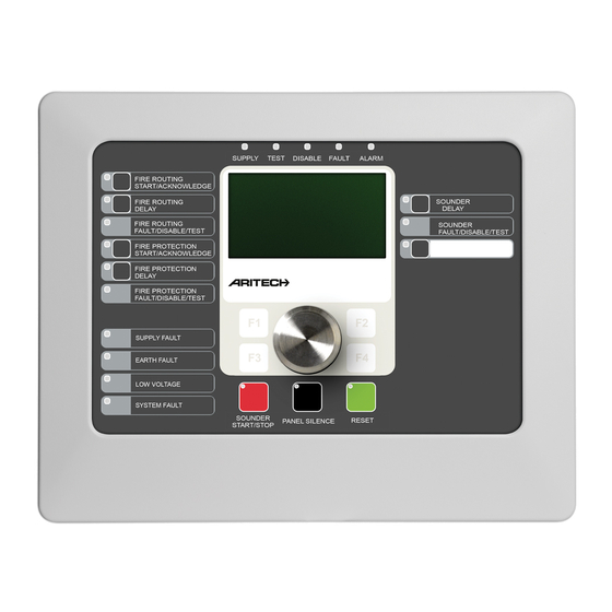
Page 7: Product Overview
Product overview This topic provides an introduction to the control panel user interface, LCD, operator controls, and indicators. For a detailed overview of front panel controls and indicators, see “Front panel controls and indicators” on page 5. The user interface Figure 1: Fire panel user interface (with fire routing and fire protection controls) 1. - Page 8 Figure 2: Evacuation panel user interface 1. Supply LED 14. Panel Silence button and LED 2. General Test LED 15. Sounder Start/Stop Button and LED 3. General Disable LED 16. System Fault LED 4. General Fault LED 17. Low Battery LED 5.
-
Page 9: Front Panel Controls And Indicators
Configuration options Depending on your configuration, the labels for some interface buttons may change. See Table 2 below. Table 2: Configured changes to interface buttons and LEDs Item EN 54 NEN 2575 All Output Groups Start/Stop All Evacuation Start/Stop Programmable output group start/stop Evacuation area sounders start/stop Sounder Start/Stop Fire Sounder Start/Stop... - Page 10 Control/LED LED colour Description Fire Routing Delay Yellow Enables or disables a previously configured fire button and LED routing delay. Cancels a delay as it counts down and activates fire routing. A steady LED indicates that a delay is configured and enabled.
- Page 11 Control/LED LED colour Description Programmable Yellow Starts or stops the the output group associated with start/stop button and the programmable button. A steady yellow LED indicates that the output group associated with the button is active. A flashing yellow LED indicates that a delay is counting (the output group is activated when the configured delay elapses or when the delay is cancelled).
- Page 12 Evacuation panel controls and indicators The table below includes information for the additional controls and indicators for evacuation panels. Note: If the evacuation panel is operating in NEN 2575 mode, only sounder output groups can be associated with the programmable start/stop buttons. Table 4: Evacuation panel controls and indicators Control/LED LED colour...
-
Page 13: Lcd Controls And Indicators
There are two fire routing groups, the first is in activated status and the second is in acknowledged status. The fire routing indication displays the acknowledged status but not the activation status (the acknowledgement status takes priority). For more information on your control panel configuration and indications, contact your installation or maintenance contractor. - Page 14 Icons displayed on the LCD Icons displayed on the LCD are shown below. Table 5: LCD icons and descriptions Icon Description This icon indicates that the primary sensitivity mode Day mode (network) setting for control panels in the fire network is day mode.
-
Page 15: Acoustic Indicators
Indication of remote and local events on the LCD The local control panel ID is always displayed on the LCD (see Figure 3 on page If your control panel forms part of a fire network, the event notification includes the panel ID reporting the event as follows: •... -
Page 16: Status Indications
Condition type Description Maximum loops exceeded in a The number of loops in a fire network exceeds the network maximum allowed New node in the fire network A control panel has been added to the fire network Output group activation An output group is activated Prealarm A device (and corresponding zone) is in prealarm... - Page 17 Each zone message indicates: • The zone identifier and description, the timestamp, and the device description of the first alarm reported in the zone • A counter with the total number of devices in alarm in the zone. To see the details of the devices in alarm, press F1 (Show Events) and select Alarms.
- Page 18 Evacuation If your control panel is configured for evacuation control, evacuation is indicated as follows: • The Confirm LED is steady. • The evacuation area alarm LED is steady if an evacuation alarm is active or flashing if a confirmation delay is counting. •...
- Page 19 Test Tests are indicated as follows: • The General Test LED is steady • If a zone board is installed, the corresponding zone Disabled/Test LED is steady (if the corresponding zone is included on the zone board) • The control panel buzzer sounds intermittently (short tone) For more information on the test, press F1 (Show Events) and then select Conditions.
-
Page 20: Control Panel Operation
Control panel operation User levels Access to some of the features of this product is restricted by the user level assigned to a user account. Public The public level is the default user level. This level allows basic operational tasks, such as responding to a fire alarm or fault warning at the control panel. -
Page 21: Operation Controls And Procedures
Operation controls and procedures Using the function buttons and the jog dial Use function buttons F1 to F4 and the jog dial (see Figure 3 on page 9) to navigate the LCD menus, to select menu options, and to enter passwords and system information, as shown below. -
Page 22: Public Level Operation
Public level operation Public level operations are those that can be performed by any user. No password is required to perform tasks at this level. This user level lets you: • Silence the buzzer • Cancel an active sounder, fire routing, or fire protection delay •... - Page 23 Table 9: Fire routing and fire protection delay indications Delay type Delay indications Fire routing A steady Fire Routing Delay LED indicates that a delay is enabled. A flashing Fire Routing Delay LED during a fire alarm indicates that the configured delay is active (fire routing is activated when the configured delay elapses or when the delay is cancelled).
- Page 24 Note: This information is only available if your installation or maintenance contractor has included it in the fire system configuration.
-
Page 25: Operator Level Operation
Operator level operation The operator level is protected by password security and is reserved for authorized users who have been trained to operate the control panel. The default operator user password is 2222. This user level lets you: • Perform all tasks described in “Public level operation” on page 18 •... - Page 26 A steady Sounder Start/Stop LED indicates that the sounders are active (sounding). A flashing Sounder Start/Stop LED indicates that a configured sounder delay is counting down and that sounders can be silenced (before activation) by pressing the Sounder Start/Stop button. Sounder functionality is subject to previous configuration and, depending on what your installation or maintenance contractor has selected, silenced sounders may restart automatically if another alarm event is detected.
- Page 27 Note: Evacuation panels only. This feature is subject to previous configuration by your installation or maintenance contractor and operations associated with programmable buttons and LEDs may differ from those described here. Enabling or disabling a previously configured sounder, fire routing, or fire protection delay To enable a previously configured sounder, fire routing, or fire protection delay, press the corresponding Sounder, Fire Routing, or Fire Protection Delay button.
- Page 28 Changing your password Use the Password setup menu to change your password. To change your password: 1. Select Password setup from the Main menu, and then select Change password. 2. Enter your current password. 3. Enter and then confirm your new password. 4.
- Page 29 4. Repeat step 3 for all buttons. 5. Press F2 (Exit). Performing an LCD test Perform an LCD test to confirm that the LCD is working correctly. To perform an LCD test: 1. Select Tests from the Main menu. 2. Select UI tests, and then LCD test. A test pattern displays on the LCD to help identify the location of defective pixels.
-
Page 30: Maintenance
Maintenance To ensure the correct functioning of your control panel and fire alarm system, and to comply with all European regulations, perform scheduled maintenance as described below. Quarterly maintenance Contact your installation or maintenance contractor to carry out a quarterly inspection of the fire alarm system. -
Page 31: Menu Maps
Menu maps Table 11: Operator level menu for fire alarm control panels Menu level 1 Menu level 2 Menu level 3 Test UI test Indicator test Keyboard test LCD test Reports Event log View all Attention required Revision Firmware revision Configuration revision Serial numbers Contact details... -
Page 32: Regulatory Information
Regulatory information European standards for fire control and indicating equipment These control panels have been designed in accordance with European EN 54-2, and EN 54-4 standards. In addition, they comply with the following EN 54-2 optional requirements. Table 13: EN 54-2 optional requirements Option Description Output to fire alarm devices [1]... - Page 33 European regulations for construction products This section includes both regulatory information and a summary on the declared performance according to the Construction Products Regulation 305/2011. For detailed information refer to the product Declaration of Performance (DoP). Table 14: Regulatory information Certification Certification body 0832...
Need help?
Do you have a question about the 2X-F1 and is the answer not in the manual?
Questions and answers