Aritech 2X Series Installation Manual
Hide thumbs
Also See for 2X Series:
- Quick installation manual (2 pages) ,
- Operation manual (36 pages) ,
- Quick operation manual (2 pages)
Table of Contents
Advertisement
Quick Links
Advertisement
Chapters
Table of Contents

Related Manuals for Aritech 2X Series


Summary of Contents for Aritech 2X Series
- Page 1 2X Series Installation Manual P/N 501-405003-1-31 • REV 03.10 • ISS 07NOV13...
- Page 2 Copyright © 2013 UTC Fire & Security. All rights reserved. Trademarks and 2X Series is a trademark of UTC Fire & Security. patents Other trade names used in this document may be trademarks or registered trademarks of the manufacturers or vendors of the respective products.
-
Page 3: Table Of Contents
Fire alarm system maintenance 106 Battery maintenance 107 Chapter 5 Technical specifications 109 Appendix A Default configurations 117 Appendix B PSTN country codes 119 Appendix C Menu maps 121 Appendix D Regulatory information 129 Index 131 2X Series Installation Manual... -
Page 4: Important Information
Important information Introduction This is the installation manual for the 2X Series fire alarm, repeater, and evacuation control panels. Read these instructions and all related documentation entirely before installing or operating this product. Firmware compatibility Information in this document covers control panels with firmware version 3.0 or later. - Page 5 Note: Note messages advise you of the possible loss of time or effort. They describe how to avoid the loss. Notes are also used to point out important information that you should read. 2X Series Installation Manual...
- Page 6 2X Series Installation Manual...
-
Page 7: Introduction
This chapter provides an introduction to your control panel, the main controls, and the indicators. Content Product range 2 Product compatibility 3 Product overview 4 The user interface 4 Front panel controls and indicators 6 LCD controls and indicators 10 Acoustic indicators 12 Conditions 12 2X Series Installation Manual... -
Page 8: Product Range
[2] Includes a fireman's key. Repeater functionality All control panels in a fire network can be configured for repeater functionality, provided that they have a network board installed. For more information, see “Firenet configuration” on page 55. 2X Series Installation Manual... -
Page 9: Product Compatibility
Products compatible with these control panels are listed in the supplied compatibility list. Only those products specified in the compatibility list are guaranteed to be compatible with these control panels. For further details contact your local supplier. 2X Series Installation Manual... -
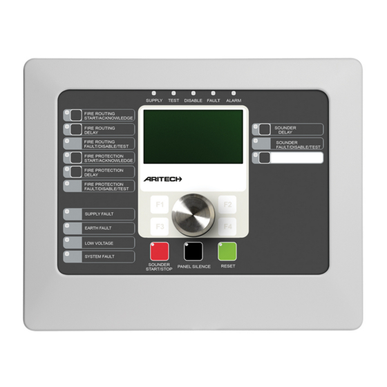
Page 10: Product Overview
9. Reserved for future use 21. Fire Routing Fault/Disabled/Test LED 10. Jog dial and function buttons 22. Fire Routing Delay button and LED 11. Reset button and LED 23. Fire Routing On/Acknowledged button and 12. Panel Silence button and LED 2X Series Installation Manual... - Page 11 25. Fire Routing On/Acknowledged button and 12. Jog dial and function buttons 13. Reset button and LED See “Assigning an output group to a programmable button” on page 90 for more information on configuring programmable buttons. 2X Series Installation Manual...
-
Page 12: Front Panel Controls And Indicators
On/Acknowledged down and activates fire routing. button and LED A flashing LED indicates that fire routing has been activated. A steady LED indicates that the fire routing signal has been acknowledged by the remote monitoring equipment. 2X Series Installation Manual... - Page 13 Low Battery LED Yellow Indicates that the control panel is running on battery power and that the remaining charge may be insufficient to guarantee continued operation. System Fault LED Yellow Indicates a control panel system failure. 2X Series Installation Manual...
- Page 14 A steady LED indicates that the buzzer has been silenced. Reset button and LED Yellow Resets the control panel and clears all current system events. A steady LED indicates that the control panel can be reset in the current user level. 2X Series Installation Manual...
- Page 15 There are three sounder output groups, the first in fault status, the second in delayed status, and the third in activated status. The sounder indications display the fault status of the first group, the delay status of the second group, and the activated status of the third group. 2X Series Installation Manual...
-
Page 16: Lcd Controls And Indicators
5. Message display area 6. Soft keys (menu options linked to function buttons F1, F2, F3, and F4) 7. Jog dial 8. Function buttons F1, F2, F3, and F4 9. Local control panel ID (in a fire network) 2X Series Installation Manual... - Page 17 This icon indicates a manual call point alarm Manual call point alarm (“hausalarm”). This is a local alarm with no fire routing (“hausalarm”) [1] activation. [1] These icons appear in the message display area with the notification details. 2X Series Installation Manual...
-
Page 18: Acoustic Indicators
Extinguishing status [1] Extinguishing is blocked, disabled, or has a fault Extinguishing I/O device [1] An extinguishing I/O device is active, being tested, is disabled, or has a fault Input activation An input is activated (subject to configuration) 2X Series Installation Manual... - Page 19 [1] A rule consists of one or more states (combined by Boolean operators) that are configured to trigger specific system actions after a specific confirmation time. Rules are created using the Configuration Utility. 2X Series Installation Manual...
- Page 20 Chapter 1: Introduction 2X Series Installation Manual...
-
Page 21: Installation
Connecting loop devices 28 Connecting inputs 28 Connecting outputs 28 Connecting the mains power supply 30 Connecting the batteries 32 Connecting expansion boards 32 Connecting a fire network 32 Connecting an external printer or ASCII terminal 34 2X Series Installation Manual... -
Page 22: Electrical Safety
Caution: Equipment damage hazard. This product is sensitive to electrostatic discharge (ESD). To avoid damage, follow accepted ESD handling procedures. 2X Series Installation Manual... -
Page 23: Cabinet And Pcb Layout
12. Power supply connector 5. Earth studs 13. Power supply 6. Ethernet connector 14. Mains terminal block and fuse 7. USB type B connector 15. Battery area 8. USB type A connectors 16. Mounting holes 17. User interface connector 2X Series Installation Manual... - Page 24 5. USB type B connector 12. Mounting holes 6. USB type A connectors 13. Battery area 7. COM0 and COM1 serial ports 14. User interface connector Figure 6: Small cabinet with main PCB and chassis removed to show power supply 2X Series Installation Manual...
-
Page 25: Cabinet Installation
Fixing the cabinet to the wall Fix the cabinet to the wall using five M4 × 30 screws and five Ø 6 mm wall plugs, as shown in Figure 7 below. Figure 7: Mounting hole locations 2X Series Installation Manual... -
Page 26: Adding The Menu Inserts
5. Insert screws in positions (2) and tighten. 6. Insert screws in position (3) and tighten. 7. Tighten screw in position (1). Adding the menu inserts Add the control panel interface menus as shown below. Figure 8: Adding the menu inserts 2X Series Installation Manual... -
Page 27: Connecting The User Interface Cable
Be sure to use the correct version of the insert for your product. Connecting the user interface cable Connect the user interface cable as shown below. Figure 9: Connecting the user interface cable 2X Series Installation Manual... -
Page 28: Connecting The Internal Printer And Loading Paper
The internal printer is only available on selected models. Connecting the internal printer Connect the internal printer as shown below. Figure 10: Connecting the internal printer 1. Internal printer 2. Internal printer PSU 3. Control panel PCB 2X Series Installation Manual... - Page 29 Chapter 2: Installation Loading paper Load the paper for the internal printer as shown below. Figure 11: Loading the paper for the internal printer 2X Series Installation Manual...
-
Page 30: Connections
See Figure 4 on page 17 or Figure 5 on page 18 for the location of the earth studs. The PCB terminal earthing connections only improve noise immunity in very specific environmental conditions. In some cases, leaving the earth fully isolated provides the best protection against EMI. 2X Series Installation Manual... -
Page 31: Overview Of Fire System Connections
Overview of fire system connections Figure 12: Overview of typical fire system connections with a single Class A loop For input activation characteristics, see “Connecting inputs” on page 28. 2X Series Installation Manual... -
Page 32: Connecting Loops
Keep loop cabling away from high-voltage cables (or any other source of interference). • Star, stub, and T-tap configurations are not recommended. • Install loop devices with a high current consumption as close as possible to the control panel. 2X Series Installation Manual... - Page 33 Connect Class B loops as shown in Figure 14 below. Connection may be made to either the A connectors (as shown) or to the B connectors, but not to both. Class B loops are supervised for short circuit. Figure 14: Class B loop connection 2X Series Installation Manual...
-
Page 34: Connecting Loop Devices
Configurable outputs (the default configuration is Short circuit, open sounder output). The number of configurable circuit outputs depends on the control panel model (see the topic below). Note: These outputs comply with EN 54-13 requirements when configured as Class A outputs. 2X Series Installation Manual... - Page 35 All outputs are polarity sensitive. Observe polarity or install a 1N4007 diode or equivalent to avoid inverted activation issues due to reverse polarity supervision. Connecting auxiliary equipment Connect auxiliary equipment to 24V AUX as shown in Figure 12 on page 25. 2X Series Installation Manual...
-
Page 36: Connecting The Mains Power Supply
Feed all mains cables through the appropriate cable knockouts and connect them to the fuse terminal block as shown in Figure 15 on page 31. 2X Series Installation Manual... - Page 37 The default power setting is 230 VAC. For 115 VAC operation use a small screwdriver to change the power setting switch, located on the side of the power supply unit, as shown in Figure 16 below. Figure 16: Selecting 115 or 230 VAC operation 2X Series Installation Manual...
-
Page 38: Connecting The Batteries
Each network board has two ports. Each port is connected (point to point) to the corresponding ports of the network board in another control panel. Figure 17: Network board connections Two wiring options are possible: • Ring configuration • Bus configuration 2X Series Installation Manual... - Page 39 Bus network configuration is not recommended. It does not provide for redundancy in the transmission path and creates a fire network much more sensitive to faults. For bus configuration (Class B), connect control panels as shown below. Figure 19: Fire network bus configuration 2X Series Installation Manual...
-
Page 40: Connecting An External Printer Or Ascii Terminal
Serial port Output device COM0 EPSON LX300 printer COM1 ASCII terminal See Figure 4 on page 17 for COM serial port and RS-232 interface board connector locations. See “Printer configuration” on page 68 for configuration options. 2X Series Installation Manual... -
Page 41: Configuration And Commissioning
Panel configuration 53 ID configuration 54 Regional options 55 Firenet configuration 55 Communications configuration 59 Other settings 61 Load/Save configuration 64 Expansion board configuration 66 Load auxiliary files 66 Firmware updates 67 Printer configuration 68 DACT configuration 69 2X Series Installation Manual... -
Page 42: Introduction
The control panel automatically exits from a restricted user level and reverts to the public user level after a few minutes if no button is pressed. The automatic timeout period depends on the active user level, as shown below. 2X Series Installation Manual... -
Page 43: Configuration Overview
An action is the activation of output groups or the execution of programmable commands in the system. Rules programming is also known as cause and effect programming, I/O logic activation, etc. 2X Series Installation Manual... - Page 44 Press the jog dial to confirm the selection. The control panel ID on the LCD is white text with a dark background when the jog dial is active (the control panel is waiting for input). 2X Series Installation Manual...
-
Page 45: Maintenance Level Operation And Configuration
View and save reports • Disable or enable system features or loop devices • Test zones, inputs, outputs (including output groups), and batteries • Change the user passwords • Locate devices • Activate service mode for testing purposes 2X Series Installation Manual... -
Page 46: The Panel Setup Menu
5. If required, select YES for Firenet time sync to synchronize the date and time across all control panels in a fire network. 6. Press F4 (Enter), and then press F1 (Back). 7. Press F2 (Exit) to exit the menu. 2X Series Installation Manual... - Page 47 Here are two examples of day/night mode scheduling. To start day mode at midnight and end at 06:00, set the day mode start time to 00:00 and the night mode start time for the same day to 06:00. 2X Series Installation Manual...
- Page 48 Configures the control panel to process or override sounder, fire routing, and night mode fire protection delays when the control panel is in night mode. To change the configuration: 1. Select Panel setup from the Main menu. 2. Select Day/Night mode, and then select Day/Night setup. 2X Series Installation Manual...
- Page 49 Some control panels in the network may be operating with locally-defined sensitivity settings. The day/night mode setting for all control panels in a fire network is included in the Firenet status report. For more information on the global controls, see “Global controls” on page 57. 2X Series Installation Manual...
-
Page 50: The Communications Menu
1. Select Panel setup from the Main menu, and then select Communications. 2. Select Remove USB device. A message displays on the LCD confirming the operation. 3. Press F2 (Exit) to exit the menu. 4. Open the control panel door and remove the flash drive. 2X Series Installation Manual... -
Page 51: The Disable/Enable Menu
In maintenance level operation, to disable Class A outputs each output used must be disabled (for example, if OUT1 and OUT2 are combined to create a single Class A output, then both OUT1 and OUT2 must be disabled individually). 2X Series Installation Manual... -
Page 52: The Test Menu
The control panel resets the initiating device after 5 seconds and clears the alarm (manual call points must first be closed before an automatic reset can be applied) • The event is recorded in the event log 2X Series Installation Manual... - Page 53 2. Select the ID of the output group you want to test, and then select YES (to activate the output group) or NO (to deactivate the output group). 3. Press the jog dial again to end the test. 4. Press F2 (Exit) to exit the menu. 2X Series Installation Manual...
- Page 54 “Battery maintenance” on page 107. To test the batteries: 1. Select Test from the Main menu. 2. Select Battery test. A message confirming battery status displays on the LCD. 3. Press F2 (Exit) to exit the menu. 2X Series Installation Manual...
-
Page 55: The Reports Menu
Displays the current status information for control panel devices. Device information available in real time includes: instant, mean, maximum, and minimum analog values, alarm level, and communication error rate. Panel I/O status Displays the current status information for the control panel inputs and outputs. 2X Series Installation Manual... - Page 56 4. Select Reports from the Main menu. 5. Select Event log, and then select Backup. 6. Follow the on-screen instructions. 7. Press F2 (Exit) to exit. 8. Remove the flash drive as described in “Removing a USB device” on page 2X Series Installation Manual...
- Page 57 5. Select Save report, and then select ALL or the report to be saved. 6. Press F2 (Exit) to exit. 7. Remove the USB flash drive as described in “Removing a USB device” on page 44. 2X Series Installation Manual...
-
Page 58: The Password Setup Menu
A list of the user accounts that you have permission to edit is displayed. 2. Select the user account you want to delete. You cannot delete the default operator user account. 3. Press F4 (Delete) to delete the selected account. 2X Series Installation Manual... -
Page 59: Installer Level Operation And Configuration
Table 20: Control panel configuration Option Description ID configuration Configures the control panel Firenet ID (for the fire network) and description. The description is displayed on the LCD when the control panel is in standby. 2X Series Installation Manual... -
Page 60: Id Configuration
2. Select ID configuration. 3. Enter the ID and description. 4. Press F4 (Enter), and then press F1 (Back). 5. Press F1 (Save), F3 (Apply), F4 (Discard), or F2 (Exit). Remember to apply saved settings from the Main menu. 2X Series Installation Manual... -
Page 61: Regional Options
Configures the control panels in the network that the control panel being configured will repeat. Global controls Configures global control options for networked control panels and repeaters. Event filter Configures the types of events to repeat from other control panels in the fire network. 2X Series Installation Manual... - Page 62 For example, if the control panel event filter has condition and fault reporting disabled, the repeater repeats only alarm, prealarm, alert, and technical alarm conditions. 2X Series Installation Manual...
- Page 63 2. Select Firenet, and then select Global controls. 3. Select the control panel from the list, and then select YES (to allow global control) or NO (to stop global control). 4. Press F4 (Enter), and then press F1 (Back). 2X Series Installation Manual...
- Page 64 [1] Used to allow control panels within the network to have locally-defined day/night mode settings. If this setting is not activated, the control panel does not send the day/night mode change and does not process these commands when received from other control panels in the fire network. 2X Series Installation Manual...
-
Page 65: Communications Configuration
Table 25: Default TCP/IP settings Option Default value IP address 192.168.104.140 Subnet mask 255.255.255.0 Gateway 0.0.0.0 Port 2505 [1] [1] If the default port is changed, the port configuration in the configuration utility PC application must also be updated. 2X Series Installation Manual... - Page 66 To configure the email server: 1. Select Panel setup from the Main menu, and then select Communications. 2. Select Email server. 3. Enter the Host (domain) and the IP address of the email server. The Host name is optional. 2X Series Installation Manual...
-
Page 67: Other Settings
6. Press F1 (Save), F3 (Apply), F4 (Discard), or F2 (Exit). Remember to apply saved settings from the Main menu. Note: If NO is selected for either option, the corresponding faults are not recorded in the event log. 2X Series Installation Manual... - Page 68 4. Select Time, and then enter the duration in seconds (1 to 10). Enter the school bell duration in seconds if you selected NO in step 3, or leave the duration blank if you selected YES. 5. Press F4 (Enter), and then press F1 (Back). 2X Series Installation Manual...
- Page 69 If the PulseT value is 0, the output activation is continuous. 5. Press F4 (Enter), and then press F1 (Back). 6. Press F1 (Save), F3 (Apply), F4 (Discard), or F2 (Exit). Remember to apply saved settings from the Main menu. 2X Series Installation Manual...
-
Page 70: Load/Save Configuration
1. Open the control panel door and insert the USB flash drive with the configuration file into either of the USB type A connectors (see Figure 4 on page 17). Close the control panel door. 2. Select Panel setup from the Main menu. 2X Series Installation Manual... - Page 71 2. Select Default configuration and confirm your selection. 3. Press F4 (Enter), and then press F1 (Back). 4. Press F1 (Save), F3 (Apply), F4 (Discard), or F2 (Exit). Remember to apply saved settings from the Main menu. 2X Series Installation Manual...
-
Page 72: Expansion Board Configuration
1. Open the control panel door and insert the USB flash drive into either of the USB type A connectors (see Figure 4 on page 17). Close the control panel door. 2. Select Panel setup from the Main menu. 2X Series Installation Manual... -
Page 73: Firmware Updates
Always back up your configuration data before updating the control panel firmware. Select this option to load control panel firmware updates provided by the manufacturer. The update application may only be available in English. 2X Series Installation Manual... -
Page 74: Printer Configuration
Configures the external printer for report printing NWEvent [2] Configures the printing of system events for all control panels in the network Alarm [2] Configures the printing of alarm events Fault [2] Configures the printing of fault events 2X Series Installation Manual... -
Page 75: Dact Configuration
Configures Ethernet settings for monitoring network communication with the central monitoring station (CMS) CMS config Configures CMS settings PSTN config Configures PSTN settings GPRS config [1] Configures GPRS settings [1] Requires an optional GPRS expansion board to be installed. 2X Series Installation Manual... - Page 76 Configures the minimum number of consecutive heartbeat failures required to indicate a communication error with the central monitoring station To change the configuration: 1. Select Panel setup from the Main menu. 2. Select Other settings, and then select DACT config. 2X Series Installation Manual...
- Page 77 [1] In the event of communication problems reporting an event to the primary CMS, the control panel attempts to send the event notification to the configured backups in order of the assigned priority. [2] The global FR_ERM setting in General Configuration takes priority over any individual CMS setting configured here. 2X Series Installation Manual...
- Page 78 3. Select PSTN config. 4. Configure all required settings. 5. Press F4 (Enter), and then press F1 (Back). 6. Press F1 (Save), F3 (Apply), F4 (Discard), or F2 (Exit). Remember to apply saved settings from the Main menu. 2X Series Installation Manual...
-
Page 79: Field Configuration
Automatically configures installed loop devices to their default settings. Loop device configuration Configures installed loop devices or change default settings. Zone configuration Configures zones. Panel I/O configuration Configures control panel input and output functionality. Output groups Configures output groups. 2X Series Installation Manual... -
Page 80: Loop Device Configuration
(output group number 981) • Assign the default initial zone to zone 1 By default all zones activate all output groups with no delay. Note: Autosetup is incremental and retains the device text description for previously configured devices. 2X Series Installation Manual... -
Page 81: Zone Configuration
1 to 4095 (zones with higher numbers will be discarded). Table 37: Maximum number of zones One-loop control panel 64 zones max. Two-loop control panel 128 zones max. Two-loop control panel with loop board 256 zones max. 2X Series Installation Manual... - Page 82 “Initial zone” on page 77 for more information. Assign first ZI LED to Configures the initial zone LED for an installed zone zone LED indicator board. See “First zone indicator LED” on page 77 for more information. 2X Series Installation Manual...
- Page 83 The initial zone range is as follows: • Between 01 and 9960 for a 40-zone indicator board • Between 01 and 9980 for a 20-zone indicator board • Between 01 and 9976 for a 24-zone indicator board 2X Series Installation Manual...
- Page 84 See “Zone alarm confirmation” on page 79 for more information. Area [1] [2] Configures the area number for zone types requiring confirmation by an area. See “Area configuration” on page 81 for more information. 2X Series Installation Manual...
- Page 85 Full alarm status is not confirmed until a second alarm is reported in the same zone or in a configured area. See “Area configuration” on page 81 for more information on areas. 2X Series Installation Manual...
- Page 86 The alarm is confirmed by two different manual call points in the same local area irrespective of which device first reports the alarm event. A detector alarm places the zone in alert status. 2X Series Installation Manual...
- Page 87 Fire routing output groups are not activated in the event of an alarm in a zone operating in this mode. [1] The control panel will not allow configuration of zone devices or inputs that do not meet the corresponding criteria shown in the Description column. 2X Series Installation Manual...
-
Page 88: Panel I/O Configuration
Input types are shown in Table 46 below. The default mode for all inputs is LG (logged activation: an unlatched condition stored in the event log). To configure a control panel input: 1. Select Field setup from the Main menu. 2X Series Installation Manual... - Page 89 (or until the output is deactivated). Fault Warning Output Open Supervision. By using a 2010-FS-EOL end- of-line device, the control panel can supervise the open circuit condition of the Fault Warning output. 2X Series Installation Manual...
- Page 90 Remember to apply saved settings from the Main menu. Panel output configuration Configurable options for control panel outputs are shown below. Table 47: Configurable options for control panel outputs Option Description Type Configures the output operation mode 2X Series Installation Manual...
- Page 91 Select this option for an output that activates when the control panel is in fault status TEST Select this option for an output that activates when the control panel is in test status Select this option for an output that activates when the control panel is in disable status 2X Series Installation Manual...
- Page 92 The default control panel output groups are shown below. Note: This option is not available on repeater panels. Table 49: Default output groups Group number Type Description Sounder and supervised outputs. Nonsupervised relay outputs. These outputs are assigned to this group during autosetup. 2X Series Installation Manual...
- Page 93 5. Enter a brief text description for the output group. 6. Press F4 (Enter), and then press F1 (Back). 7. Press F1 (Save), F3 (Apply), F4 (Discard), or F2 (Exit). Remember to apply saved settings from the Main menu. 2X Series Installation Manual...
- Page 94 The output group alarm confirmation configuration options are shown in the table below. Note: Configuration requires that two independent alarm confirmations be selected from the available options and that a confirmation delay (in seconds) is entered for the corresponding output group to be activated. 2X Series Installation Manual...
- Page 95 8. Press F1 (Save), F3 (Apply), F4 (Discard), or F2 (Exit). Remember to apply saved settings from the Main menu. Note A remote extinguishing panel can be configured to receive extinguishing preactivate and activate commands associated with the local extinguishing output group confirmation. 2X Series Installation Manual...
-
Page 96: Activation Configuration
Remember to apply saved settings from the Main menu. Activation configuration Select Activation configuration options to configure the activation delays for output groups, investigation times, and general sounders behaviour (sounder silencing and second stage usage). Note: This option is not available on repeater panels. 2X Series Installation Manual... - Page 97 3. Select Group_n, and then select ALL (to configure common delay settings for all output groups of the type selected) or select the output group number (to configure custom delay settings for a single output group of the type selected). 2X Series Installation Manual...
- Page 98 1 or 5 and will not activate for all the other zones. • The Activate for all zones option allows the user to apply the delay to all zones (including those previously configured not to activate the output group). 2X Series Installation Manual...
- Page 99 5, the following can be configured with this option: • No activation for zones 100 to 119 • Activation with a 10 second delay for zones 120 to 139 2X Series Installation Manual...
- Page 100 (in seconds). See “Investigation time” on page 96 for more information on this option. 5. If warning tones are required (for second stage sounders), select Warning time, and then enter the time value (in seconds). 2X Series Installation Manual...
- Page 101 If the alarm is not acknowledged during the investigation time (by pressing the Panel Silence button), then sounders and fire routing are activated when the configured investigation time elapses. 2X Series Installation Manual...
- Page 102 [1] The maximum value must be less than the minimum delay to activate a sounder or fire routing group. [2] The minimum value must be greater than the maximum activation delay for any fire routing group. 2X Series Installation Manual...
- Page 103 [1] To configure these values, see “Sounder, fire routing, fire protection, and program output group delays” on page 91. Figure 24: Detector alarm with second stage delay Warning time (or second stage delay) Warning tone Evacuation tone Time Warning delay Delay 2X Series Installation Manual...
-
Page 104: Loop Class Configuration
To configure a loop as Class A or Class B: 1. Select Field setup in Main menu. 2. Select Loop Class and select the loop number (1 for one-loop panel; 1 or 2 for two-loop panel, etc.). 3. Select Class A or Class B. 2X Series Installation Manual... -
Page 105: Tests
Detailed device diagnostics may be requested by your regional technical support office to help troubleshoot technical issues. Use the following tests as instructed by the technical support team and give the test results to them for further analysis and assistance. 2X Series Installation Manual... -
Page 106: Password Setup
3. Enter and then confirm your new password. 4. Press F4 (Enter), and then press F1 (Back). 5. Press F1 (Save), F3 (Apply), F4 (Discard), or F2 (Exit). Remember to apply saved settings from the Main menu. 2X Series Installation Manual... - Page 107 Usernames help to identify user session activity in the event log. 4. Press F4 (Enter), and then press F1 (Back). 5. Press F1 (Save), F3 (Apply), F4 (Discard), or F2 (Exit). Remember to apply saved settings from the Main menu. 2X Series Installation Manual...
-
Page 108: Commissioning
That all inputs and outputs operate correctly • That any input/output logic (rules and actions) configuration is correct • That the fire system is functioning correctly in standby and is not reporting any alarms or faults 2X Series Installation Manual... - Page 109 Chapter 3: Configuration and commissioning • That under the alarm conditions (with all applicable devices activated), the current consumption does not exceed the power supply specifications (if the batteries are not activated the current consumption is within the specifications) 2X Series Installation Manual...
- Page 110 Chapter 3: Configuration and commissioning 2X Series Installation Manual...
-
Page 111: Maintenance
Chapter 4 Maintenance Summary This chapter includes information on fire alarm system and battery maintenance. Content Fire alarm system maintenance 106 Battery maintenance 107 2X Series Installation Manual... -
Page 112: Fire Alarm System Maintenance
Keep the outside and inside of the control panel clean. Carry out periodic cleaning using a damp cloth for the outside. Do not use products containing solvents to clean the unit. Do not clean the inside of the cabinet with liquid products. 2X Series Installation Manual... -
Page 113: Battery Maintenance
In addition to the above, the following battery charger faults may display: • Battery charger: sensor HI • Battery charger: sensor LO • Battery charger: overvoltage • Battery charger: undervoltage • Battery charger: compensation 2X Series Installation Manual... - Page 114 To power up the control panel from the batteries, press the battery start button on the control panel PCB (marked as BAT, see Figure 26 below). Keep the button pressed for approximately 5 seconds. Figure 26: Battery start-up button 2X Series Installation Manual...
-
Page 115: Technical Specifications
Loop specifications 110 Power supply specifications 110 Battery and battery charger specifications 111 LCD specifications 111 Communication port specifications 112 Fire network specifications 112 Input and output specifications 112 Internal printer specifications 113 Mechanical and environmental specifications 114 2X Series Installation Manual... -
Page 116: Loop Specifications
(with no devices connected) One-loop control panel 180 mA at 24 VDC Two-loop control panel 250 mA at 24 VDC Two-loop control panel with printer 315 mA at 24 VDC Repeater panel 110 mA at 24 VDC 2X Series Installation Manual... -
Page 117: Battery And Battery Charger Specifications
21 VDC ± 1% at 25ºC System shutdown (for battery protection) LCD specifications Display type 240 x 128 dot graphic LCD (monochromatic) LCD dimensions (L x W) 83 x 44 mm (active area) Backlight type LED style Backlight colour White 2X Series Installation Manual... -
Page 118: Communication Port Specifications
10 kΩ ≤ value ≤ 20.2 kΩ Normal value ≤ 60.2 Ω Short circuit values 8 kΩ < value < 10 kΩ High-impedance fault value ≥ 20.2 kΩ Open circuit values Configurable options See Table 46 on page 82 2X Series Installation Manual... -
Page 119: Internal Printer Specifications
24/40 Paper width 58 mm Paper weight 55 to 70 g/m² Roll dimension Ø 30 mm max. Character set ASCII standard, EPSON, International Data buffer 128 bytes Flash memory 32 KB Operating temperature 0 to 50°C 2X Series Installation Manual... -
Page 120: Mechanical And Environmental Specifications
18 x Ø 20 mm at top of cabinet 2 x Ø 20 mm at bottom of cabinet IP rating IP30 Environmental −5 to +40ºC Operating temperature −20 to +50ºC Storage temperature Relative humidity 10 to 95% noncondensing 2X Series Installation Manual... - Page 121 Chapter 5: Technical specifications Figure 27: Large cabinet dimensions and views 2X Series Installation Manual...
- Page 122 Chapter 5: Technical specifications Figure 28: Small cabinet dimensions and views 2X Series Installation Manual...
-
Page 123: Appendix A Default Configurations
All detectors, manual call points, and zone modules to the initial zone All sounders to output group 1 (sounders) All relay/non-supervised outputs to output group 301 (program) All extinguishing modules to output group 801 (extinguishing) All inputs configured as technical alarm latched 2X Series Installation Manual... - Page 124 IN1 and IN2 Technical alarm latched (T_AL) Delays All delays to 0 in all zones Sounder, fire routing, fire protection, and program groups to be activated by all zones Sounders silence disable time 60 seconds Expansion boards None 2X Series Installation Manual...
-
Page 125: Appendix Bpstn Country Codes
Slovakia Caribbean Korea Slovenia Chile Kuwait South Africa China Kyrgyzstan Spain Colombia Latvia Sri Lanka Costa Rica Lebanon Sweden Croatia Lesotho Switzerland Cyprus Liechtenstein Syria Czech Republic Lithuania Taiwan Denmark Luxembourg Thailand Dominican Rep. Macau Tunisia 2X Series Installation Manual... - Page 126 Code Country Code Dubai Malaysia Turkey Equador Malta Egypt Martinique Ukraine El Salvador Mexico Estonia Moldova Uruguay Finland Morocco France Netherlands Uzbekistan Georgia New Zealand Venezuela Germany Nigeria Yemen Ghana Norway Zambia Greece Oman Guadeloupe Pakistan 2X Series Installation Manual...
-
Page 127: Appendix C Menu Maps
Panel outputs Panel inputs Output groups Remote disable Test Zone test Output test Panel outputs Loop outputs Output group test Locate device Service mode Remote test UI test Indicators test Keyboard test LCD test Battery test 2X Series Installation Manual... - Page 128 Password setup Change password Manage users Installer user level Menu level 1 Menu level 2 Menu level 3 Field setup Autosetup Loop device configuration Zone configuration General configuration Zone configuration Area configuration Panel I/O configuration Panel inputs 2X Series Installation Manual...
- Page 129 Event filter Command filter Class B Communications TCP/IP Email accounts Email server Remove USB device Other settings 24V aux. configuration Fault mask Buzzer Re-sound sounders School bells Self-test configuration Pulse activation Configuration Restore configuration Load configuration 2X Series Installation Manual...
- Page 130 Loop outputs Output group test Locate device Service mode Remote test Diagnostics Individual device Outputs current Power supply Loop values UI test Indicator test Keyboard test LCD test Battery test Reports Event log View all Clear 2X Series Installation Manual...
- Page 131 Manage users Secure access Fire alarm repeater panels Maintenance user level Menu level 1 Menu level 2 Menu level 3 Panel setup Date and time Day/Night mode Day/Night schedule Holiday calendar Day/Night setup Communications Email accounts 2X Series Installation Manual...
- Page 132 Panel I/O status Firenet status Alarm counter Password setup Change password Manage users Installer user level Menu level 1 Menu level 2 Menu level 3 Field setup Zone configuration General configuration Panel I/O configuration Panel inputs Panel outputs 2X Series Installation Manual...
- Page 133 Load configuration Save configuration Default configuration Expansion boards Load auxiliary files Splash screens Languages Language fonts Firmware update Printer configuration Int. printer configuration Ext. printer configuration DACT configuration General configuration Ethernet configuration CMS configuration PSTN configuration 2X Series Installation Manual...
- Page 134 Configuration revision Serial numbers Contact details Panel I/O status Firenet status Rules status Save reports Current events Event log Attention required Panel I/O status Firenet status Alarm counter Password setup Change password Manage users Secure access 2X Series Installation Manual...
-
Page 135: Appendix D Regulatory Information
[1] Excluding repeaters and control panels operating in EN 54-2 Evacuation mode or NBN mode. [2] Excluding repeaters, control panels without fire routing, and control panels with fire routing operating in NBN mode. [3] Excluding repeaters and control panels without fire protection controls. [4] Excluding repeaters. 2X Series Installation Manual... - Page 136 European standards for electrical safety and electromagnetic compatibility These control panels have been designed in accordance with the following European standards for electrical safety and electromagnetic compatibility: • EN 60950-1 • EN 50130-4 • EN 61000-6-3 • EN 61000-3-2 • EN 61000-3-3 2X Series Installation Manual...
-
Page 137: Index
22 mains terminal block, 31 outputs, 28 email UI cable, 21 accounts, 60 control panel configuration manage accounts, 44 load, 64 server configuration, 60 restore default, 65 restore previous, 64 save, 65 custom screens, 66 2X Series Installation Manual... - Page 138 48 types, 83 repeater map, 57 installer user level, 36 Reports, saving, 51 internal printer configuration, 68 connection, 22 loading paper, 23 school bells, 62 service mode, 49 service mode timeout, 64 sounders re-sound, 62 2X Series Installation Manual...
- Page 139 ZI initial zone LED, 77 zone add, 76 alarm confirmation, 78 alarm confirmation types, 80 configuration, 75, 78 disable, 78 enable, 78 initial zone, 77 operating mode, 78, 81 remote zones, 76 test, 46 test/disable timeout, 78 2X Series Installation Manual...
Need help?
Do you have a question about the 2X Series and is the answer not in the manual?
Questions and answers