Advertisement
Advertisement
Chapters

Related Manuals for Honda CG125


Summary of Contents for Honda CG125
- Page 1 HONDA CG 125 Service Manual ...
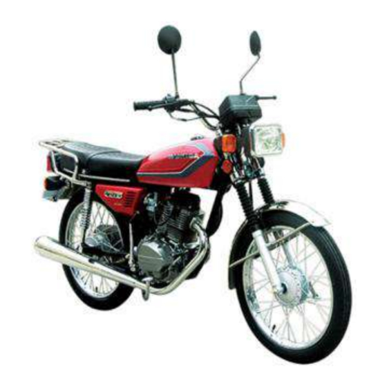
- Page 2 Introduction to the Honda CG125 The CG125 model first appeared in the UK in June 1976. It model frame numbers can be regarded in many ways as a utility version of the popular CB1 25 with which it shares many features. The basic difference...
- Page 3 Ordering spare parts When ordering spare parts for the CG125 models, it is Use only parts of genuine Honda manufacture. A few advisable to deal direct with an official Honda agent, who will pattern parts are available, sometimes at a cheaper price, but there is no guarantee that they will give such good service as be able to supply many of the items required ex-stock.
- Page 4 Safety first! Asbestos Professional motor mechanics are trained in safe working Certain friction, insulating, sealing, and other products - procedures. However enthusiastic you may be about getting on such as brake linings, clutch linings, gaskets, etc - contain with the job in hand, do take the time to ensure that your safety asbestos.
- Page 5 Routine maintenance Refer to Chapter 7 for information relating to the 1985 on Brazilian models prevent the risk of unexpected failure of any component while riding the machine and, with experience, can be reduced to a simple checklist which will only take a few moments to Periodic routine maintenance is a continuous process that complete.
- Page 6 The torque arm nut and the rear brake adjuster must also be be noted that Honda recommend minimum tread depths of 1.5 slackened during this operation. Adjust the drawbolts an equal mm (0.06 in) for the front tyre and 2.0 mm (0.08 in) for the rear;...
- Page 7 Routine maintenance capacity and place it beneath the engine unit to catch the old oil. Unscrew the drain plug on the underside of the crankcase and allow the oil to drain. Remove the large hexagon-headed plug which is located just below the left-hand engine casing. Remove the plug, followed by the spring and gauze element, and then wash all these components carefully in a suitable solvent.
- Page 8 3000 rpm the two parallel lines of the Honda parts when renewing. If the faces are only mildly full advance mark are aligned with the index mark. If the...
- Page 9 Routine maintenance Take great care not to overtighten the lockring. It is possible and close the throttle several times, allowing it to snap shut to place a pressure of several tons on the head bearings by under its own pressure. Ensure that it is able to shut off quickly over-tightening even though the handlebars may seem to turn and fully at all handlebar positions, then check that there is 2 —...
- Page 10 Oil capacity Engine/gearbox unit approx 1.0 litre (1.76 Imp pint) Front forks — at oil change CG125 120 - 130 cc (4.22 - 4.58 Imp fl oz) Valve clearances - inlet and exhaust, cold engine 0.08 mm (0.003 in) Contact breaker gap Nominal 0.35 mm (0.014 in)
- Page 11 Working conditions and tools When a major overhaul is contemplated, it is important that In addition to the basic tool kit, certain additional tools can a clean, well-lit working space is available, equipped with a prove invaluable when they are close to hand, to help speed up workbench and vice, and with space for laying out or storing the a multitude of repetitive jobs.
- Page 12 Engine (general) Air cooled, single cylinder, four stroke Type Bore Stroke Capacity Compression ratio 9.0:1 CG125 CG125 K1, B 9.2:1 CG125-C, E Piston Forged aluminium alloy Type 56.45 - 56.48 mm (2.2224 - 2.2236 in) 56.35 mm (2.2185 in) Wear limit 14.99 - 15.00 mm (0.5902 - 0.5906 in)
- Page 13 1.45 mm (0.0571 in) Cylinder bore diameter 56.50 - 56.51 mm (2.2244 - 2.2248 in) nominal Wearlimit 56.60 mm (2.2283 in) Cylinder compression pressure - throttle open, engine fully warmed up CG125, CG125 K1, B CG125-C, E Valves Valve timing 30°ABDC 30° BBDC...
- Page 14 20.050 mm (0.7894 in) General description Method of engine/gearbox removal The engine unit employed in the Honda CG125 models is of As mentioned previously, the engine and gearbox are of unit the single cylinder air cooled four stroke type. Unlike most other...
- Page 15 Chapter 1 Engine, clutch and gearbox packing pieces behind it. The exhaust is secured by two nuts to assistant to hand to help with these final stages. Note that its mounting bracket, which is secured to the frame by a bolt whilst not strictly necessary, it was found helpful to remove the and by the swinging arm pivot bolt retaining nut.
- Page 16 Honda part number Never use undue force to remove any stubborn part unless specific mention is made of this requirement. There is invariably...
- Page 17 Chapter 1 Engine, clutch and gearbox 0 ring and acts as an oil feed passage. spark plug lead, the exhaust pipe and the cylinder head steady bolt, as described in Section 5 of this Chapter. The cylinder barrel is retained by two bolts passing through Slacken and remove the three rocker cover mounting bolts, a flange on the left-hand side.
- Page 18 Fig. 1.2 Cylinder head and barrel - component parts Inlet valve guide 7 7 Gasket - 2 off < Exhaust valve guide Cylinder barrel Cylinder base gasket Cylinder head complete 25 Sparking plug Cylinder head gasket 26 Inlet stub -4 Cylinder head cover 27 O-ring <...
- Page 19 Dismantling the engine and gearbox unit: removing the generator assembly As mentioned earlier, it is recommended that the Honda flywheel puller, part number: 07933-0010000 or a cheaper pattern version is used to draw the flywheel/rotor off its taper.
- Page 20 This able. tool is available as a Honda service tool, part number: Dismantling the engine/gearbox unit: removing the cam fabricate a suitable tool from a length of thick-walled tubing.
- Page 21 9.2a Note thrust washer when removing cam gear shaft 9.2b Lift out the cam gear/cam unit 11.1a Pass screwdriver tnrough holes in pump to release mounting screws...
- Page 22 Chapter 1 Engine, clutch and gearbox 12 Dismantling the engine/gearbox unit: removing the 13 Dismantling the engine/gearbox unit: removing the clutch assembly and crankshaft pinion gearchange shaft and mechanism Lift out the clutch pushrod together with the cup in which it The gearchange shaft runs in a bore through the crankcase, seats, then remove the four bolts which secure the clutch emerging on the left-hand side of the engine.
- Page 23 clutch plates . . . 1 2.2d Clutch drum will slide off, complete with slotted washer...
- Page 24 Chapter 1 Engine, clutch and gearbox 1 2.2e Crankshaft pinion can be slid off splined crankshaft end casing the kickstart mechanism may be lifted out of the casing, having 14 Dismantling the engine/gearbox unit: removing the end- first lifted the ratchet to release spring tension. float plunger and neutral switch The crankshaft assembly can be lifted out of position.
- Page 25 2nd gear pinion 40 Coil spring 52 Kickstart spring (327) K1 on models. Note - items 2, 14 and 50 only available as a *item 16 located between items 18 and 19 fitted to CG125 set for early CGI 25 models.
- Page 26 to be withdrawn not dismantle...
- Page 27 Chapter 1 Engine, clutch and gearbox 1 6.3a Lift out mainshaft and layshaft clusters complete 1 6.3b Do not lose these shims which may remain in case • 18 Crankshaft and gearbox main bearings: removal The crankshaft bearings will remain on their shafts when the crankshaft assembly is withdrawn from the crankcase.
- Page 28 There may also be some variation in the new component, and is a job for a Honda Service Agent. It thickness of the skirt. Measure the piston skirt outside diameter...
- Page 29 Chapter 1 Engine, clutch and gearbox Piston ring wear is measured by removing the rings from force to compress the springs, the tool should be placed under slight load, and then tapped on the end to jar the collet halves the piston and inserting them in the cylinder bore using the crown of the piston to locate them approximately 25 mm (1 in) free.
- Page 30 release ... 23.1 c ... and valve springs 23.1 e Valve can be withdrawn for cleaning and examination...
- Page 31 Chapter 1 Engine, clutch and gearbox 26 Examination and renovation: cam gear and lobe, and 24 Examination and decarbonisation: cylinder head cam followers Remove all traces of carbon from the cylinder head and Examine the condition of the cam gear teeth, looking for valve ports, using a soft scraper.
- Page 32 Chapter 1 Engine, clutch and gearbox Measure the uncompressed length of the clutch springs similar inserts. Most motorcycle dealers and small engineering which should be 35.5 mm (1-398 in) when new. Should any firms offer a service of this kind. spring have settled to the specified service limit or shorter, all Sheared studs or screws can usually be removed with four springs should be renewed as a set.
- Page 33 Chapter 1 Engine, clutch and gearbox Fit the neutral switch contact to the end of the selector drum, and then lower it, contact downwards, into the crankcase half, so that the contact aligns with the neutral switch. It will be necessary to lift the selector fork assembly slightly, so that the selector fork pins can be engaged in their tracks in the selector drum.
- Page 34 washer and clip 32.2k ... and fits as shown...
- Page 35 32.2m Note: If layshaft has this circlip groove, it must be ignored. Do not fit circlip 32.2o Fit 2nd gear pinion (32T), and thrustwasher tion...
- Page 36 33.1 Lower fork is retained by spring-loaded ball 33.2a Do not omit the neutral switch contact during reassembly 33.2b Place gearbox components into left-hand casing 33.3 The crankshaft will drop into position 33.4a Fit the kickstart mechanism .. 33.4b ... ensuring that it engages correctly...
- Page 37 Chapter 1 Engine, clutch and gearbox resistance must be investigated and rectified before further reassembly takes place. 34 Preparation of crankcase jointing surfaces: joining the crankcase Coat the jointing surfaces of both crankcases with a thin 35 Replacing the crankshaft pinion, pump and layer of gasket cement, and fit the crankcase gasket to the left- gearchange mechanism...
- Page 38 35.2a Detent roller arm is retained by a shouldered bolt 35.2b Note locating pin which engages in camplate 35.2c Fit camplate and tighten bolt reassemble . . .
- Page 39 Fit and tighten the slotted securing nut to a torque setting of 4.0 - 5.0 kgf m (29 - 36 Ibf ft), using the Honda service tool or improvised peg spanner. Install a new gasket, followed by the outer half of the filter unit, tightening the three retaining screws evenly to avoid any risk of warpage.
- Page 40 36.2c Fit pressure plate and pushrod and cup 36.2b Position springs over threaded pillars 36.3b Note markings on special washer 36.3a Slide on the inner half of centrifugal filter 36.3d Use home-made tool to tighten lockring 36.3c ... which should be fitted thus...
- Page 41 Chapter 1 Engine, clutch and gearbox Fit the endfloat plunger in its bore, and depress it against spring pressure while the retaining bolt is tightened. Place the generator stator in position, noting the flat at the top which engages with the head of the cam gear shaft. Ensure that the rubber fillet through which the generator cables pass is located correctly.
- Page 42 37.3a Do not omit thrust washer or small spring when 37.2b ... aligning the timing marks as shown refitting cam gear shaft 37.4a Reconnect lead to neutral switch 37.3b Depress end float plunger while single bolt is tightened 38.1 Fit sprocket and retain with the locking plate and bolts 37.4b Ensure that generator leads pass behind guide plate...
- Page 43 Chapter 1 Engine, clutch and gearbox and screwed lightly into the head of the cam follower pivot 39 Refitting the piston, cylinder barrel, cylinder head and shaft. Fit the two pushrods, ensuring that they seat in the cam rocker arms follower cups.
- Page 44 Chapter 1 Engine, clutch and gearbox 39.7a Fit new head gasket. Note position of dowels 39.7b Ensure that pushrods engage in cam followers correctly 39.8a Refit pushrod guide and rocker assembly ... 39.8b ... oiling them liberally 40 Refitting the engine/gearbox unit in the frame It is worth checking at this stage that nothing has been omitted during the rebuilding sequences.
- Page 45 Chapter 1 Engine, clutch and gearbox ensuring that all gaskets and/or O-rings are renewed if located inside the flange recess, and tighten the two retaining necessary, that all components are refitted the correct way nuts securely, followed by the rear mounting fasteners. round and in the correct order and that the fasteners are Refit the rear chain, together with the gearbox sprocket if it securely tightened.
- Page 46 40.3b Reconnect clutch cable, and check adjustment 40.3a Push breather pipe over crankcase stub 40.4a Footrest assembly bolts onto underside of crankcase 40.3c Refit the carburettor, noting guide for HT cable • 40.4c ... then fit exhaust system. Note packing pieces 40.4b Fit new sealing ring in the exhaust port ...
- Page 47 Chapter 1 Engine, clutch and gearbox 41 Starting and running the rebuilt engine away. Do not despair if the engine will not fire up at first, as it is quite likely that the excess oil will foul the spark plug, Make a final check around the engine to ensure that necessitating its removal and cleaning.
- Page 48 Chapter 1 Engine, clutch and gearbox Symptom Cause Remedy Noisy engine Tappet noise: Excessive tappet clearance Check and reset. Weakened or broken valve spring Renew springs. Knocking noise from cylinder: Worn piston and cylinder bore Rebore cylinder and fit oversize piston. Carbon in combustion chamber Decoke engine.
-
Page 49: Table Of Contents
Overall Including reserve of 2 litres (0.4 Imp gal) Fuel grade and type Either leaded three-or four-star (minimum octane rating of 91) or unleaded premium Carburettor CG125 up to 1020010 077A-A PD88E-A/B 1422468 PD88E-C CG125-B 1422469 on PD88E-E CG125-C up to 1608462... -
Page 50: Petrol Tap: Removal, Repair And Replacement
Chapter 2 Fuel system and lubrication underside of the top, and disengaging the cable end from its recess in the valve. The needle is held by a spring clip, which is itself positioned by a second clip inside the valve. It is normally advisable to leave this assembly undisturbed unless obviously worn. -
Page 51: Carburettor Adjustment - Pre (T)Pfc Type
Chapter 2 Fuel system and lubrication 5.3b It is not normally necessary to remove heat shield 5.3a Remove carburettor body from inlet port carburettor fuel level. If the needle seat is worn or damaged it Carburettor adjustment - pre (T)PFC type must be renewed also;... -
Page 52: Carburettor: (T)Pfc Type
Carburettor: (T)PFC type CG125-C and E models are fitted with Honda's (Transient) Power Fuel Control carburettor. This is an economy carburettor designed to run on a weaker mixture, so reducing fuel consump- tion. - Page 53 6.3a Main jet can be unscrewed for cleaning . 6.3b . . . as can the jet holder Fig. 2.2 Carburettor - PD88E type Rubber cap Cable adjuster Mixing chamber top Gasket 1 7 Float and pivot pin Return spring Jet needle assembly Throttle valve 20 Float bowl...
-
Page 54: Elements
Chapter 2 Fuel system and lubrication system is kept airtight, particularly at the exhaust port. Air leaks here will cause mysterious backfiring when the machine is on overrun, as air will be drawn in causing residual gases to be ignited in the exhaust pipe. To this end, make sure that the com- posite sealing ring is renewed each time the system is removed. - Page 55 12.2a Note alignment marks on oil pump components 12.2c ... to allow pinion ... 12.3 Check pump components as described 13.1 Centrifugal filter can be dismantled for cleaning...
- Page 56 Chapter 2 Fuel system and lubrication 14 Fault diagnosis: fuel system and lubrication Symptom Cause Remedy Excessive fuel consumption Air cleaner choked or restricted Clean or renew. Fuel leaking from carburettor. Float sticking Check all unions and gaskets. Float needle seat needs cleaning.
-
Page 57: Fault Diagnosis
Chapter 3 Ignition system Refer to Chapter 7 for information relating to the 1985 on Brazilian models Contents General description Ignition coil : checking Generator : checking the output Condenser : location, removal and replacement Contact breaker : adjustment Spark plug : checking and re-setting the gap Contact breaker : removal and renewal Fault diagnosis Checking the ignition timing... -
Page 58: Contact Breaker: Adjustment
Honda opening. Examine the contact faces. If they are dirty, burnt or puller or a cheaper pattern version of it must be used. -
Page 59: Checking The Ignition Timing
Chapter 3 Ignition system 3.1 Automatic timing unit in flywheel rotor may be lubricated 3.3 Check contact breaker gap using feeler gauge lightly 4.3 Flywheel rotor centre has thread to accept extractor 4.4 A : E clip. B : Fixed contact securing screw C : Terminal Checking the ignition timing The ignition timing can be checked using a battery and bulb arrangement connected as shown in the accompanying... -
Page 60: Condenser: Location, Removal And Replacement
Honda Service Agent or Auto-Electrical specialist for generated. If the correct grade of plug is fitted, however, it will a more thorough check. - Page 61 Bulb should not light Fig. 3.4 Condenser: test sequence B: Using a multimeter 6V10-20W Bulb should not light Bulb should not light. Bulb should light. Fig. 3.5 Ignition coil: test procedure...
- Page 62 Electrode gap check - use a wire type gauge for best results Electrode gap adjustment - bend the side electrode using the correct tool Normal condition - A brown, tan or grey firing end indicates that the Ash deposits - Light brown deposits encrusted on the electrodes and engine is in good condition and that the plug type is correct insulator, leading to misfire and hesitation.
- Page 63 Chapter 3 Ignition system 9 Fault diagnosis : ignition system Symptom Cause Remedy Engine will not start Plug faulty Check plug and adjust gap or renew. Renew. Defective ignition coil Clean or renew and check gap. Dirty points Check for arcing. Renew condenser. Poor points contact Plug gap incorrect or has whiskered Adjust and clean or renew.
- Page 64 The front forks are of traditional telescopic design, being controlled The Honda CG 125 utilises a frame of open diamond type, by hydraulic dampers. Rear suspension is provided by a swing-...
-
Page 65: Front Forks: Removal - General
Using a 46mm C spanner (available as a Honda service Before any dismantling work can be undertaken, the tool, part number: 07902 - 2400000), slacken off the lockring machine should be placed on the centre stand and blocked which retains the steering column. -
Page 66: Front Forks: Removing The Fork Legs From The Yokes
On CG125 models the shrouds will scarred. If the restrictor is to be removed, press the stanchion remain in position. - Page 67 Fig. 4.1 Front forks - CG125 model Reflector - 2 off Seat - 2 off 12 Restrictor - 2 off 23 Fibre washer - 2 off Right-hand fork assembly Fork spring - 2 off 25 Drain plug - 2 off Spring guide —...
- Page 68 Chapter 4 Frame and forks diameter measured and compared with the figures given in the Specifications section of this Chapter. Play between the lower bush/piston and the inside of the lower leg, must not exceed 0.2 mm (0.008 in). The lower leg bore and the fork stanchions must also be examined for signs of scoring, which is usually caused by grit particles becoming embedded in the seal lip.
- Page 69 7.6a Note the position of spring rings ... 7.4b ... and lower, plain bush, for wear 7.6b ... which locate the bushes on the stanchion 7.6c Do not omit restrictor, if removed 7.6d Fit lower leg over bushes 7.6e Renew seal and replace the circlip...
-
Page 70: Fork Legs: Dismantling, Examination And Renovation - Cg125 K1. B, C And E Models
Fork legs: dismantling, examination and renovation - Refit the front mudguard, headlamp, speedometer and CG125 K1. B, C and E models handlebars; note that the handlebar punch marks should be aligned with the edge of the top yoke mounting, that the clamps... -
Page 71: Frame Assembly: Examination And Renovation
Chapter 4 Frame and forks Fig. 4.3 Frame - component parts Clamp Wiring clip Frame Front engine plate Right-hand head steady plate Left-hand head steady plate Frame identification plate Screw Nut- 10 off Washer Washer- 11 off Spring washer— 6 off Bolt -2 off To check for wear in the swinging arm bushes, hold the frame firmly in one hand and with the other, shake the rear... - Page 72 1 1.4a Slacken and remove pivot shaft nut Fig. 4.4 Front forks - CG125 K1 and later models Upper bush Top bolt Washer Dust seal Stanchion 14 Lower leg Circlip Backing ring Oil seal 1 1.4b ... and withdraw the pivot shaft...
-
Page 73: Renovation
Chapter 4 Frame and forks 1 1.5 Bushes can be pressed out if worn 1 1.6 Check that torque arm mounting is secure Fig. 4.5 Swinging arm and chain enclosure Upper chain enclosure Torque arm 21 Washer half Swinging pivot Footrest rubber —... -
Page 74: Centre Stand: Examination
Chapter 4 Frame and forks Fig. 4.6 Rear suspension units Suspension unit - 2 off Washer - 2 off Washer - 2 Damper - 2 off Adjustment cam Domed nut - 2 off Rubber bush Spacer Washer Metal sleeve Spring guide Grab rail Domed nut - 2 off Spring... -
Page 75: Speedometer Head: Removal And Replacement
Chapter 4 Frame and forks 19 Steering lock: removal and replacement The steering lock is situated at the front of the machine, by The speedometer is secured to a bracket that bolts to the the bottom fork yoke. It is advisable to use it whenever the top yoke, on which the speedometer head is rubber mounted to machine is left unattended, even for a short time. -
Page 76: Fault Diagnosis
Chapter 4 Frame forks 21 Fault diagnosis: frame forks Symptom Cause Remedy Bent frame Check, and renew. Twisted forks Check, and renew. handlebars Check and realign. Wheels out of alignment Machine rolls at low speed Overtight steering head bearings Slacken until adjustment is correct. Machine judders when front Slack steering head bearings Tighten, until adjustment is correct. - Page 77 Chapter 5 Wheels, brakes and tyres Refer to Chapter 7 for information relating to the 1985 on Brazilian models Contents General description Rear brake : examination and renovation Front wheel : examination and renovation Rear wheel bearings : removal and replacement ...
-
Page 78: Front Wheel: Removal
Chapter 5 Wheels, brakes and tyres borne in mind that excessive skimming will change the radius of Front wheel: removal the drum in relation to the brake shoes, therefore reducing the friction area until extensive bedding in has taken place. Also full With the machine supported on the centre stand, block the adjustment of the shoes may not be possible. - Page 79 3.2 Detach the speedometer and brake cables 3.3 Withdraw the wheel spindle, and lower the wheel clear 4.1 a Brake plate assembly can be lifted out of drum ... 4.5 Method of removing brake shoes for inspection or renewal 4.2 Examine the brake drum surface for signs of scoring...
-
Page 80: Adjusting The Front Brake
Chapter 5 Wheels, brakes and tyres adjusted by removing the operating arm from the brake camshaft and rotating it by one or two splines until the angle is correct. Ensure that all components are correctly secured on reassembly. Front wheel bearings: removal and replacement There are two bearings in the front wheel. -
Page 81: Rear Wheel: Examination
Chapter 5 Wheels, brakes and tyres Rear wheel: examination Place the machine on the centre stand and before removing the rear wheel, follow the procedure described for checking the front wheel for alignment of the rim, loose or broken spokes or any other defects. -
Page 82: Rear Brake: Examination And Renovation
Chapter 5 Wheels, brakes and tyres Remove the spring pin which retains the torque arm nut, then remove the nut and disengage the torque arm from the brake plate. Slacken off the two wheel spindle drawbolt adjusters, having made a note of their position against the graduations on the fork ends. -
Page 83: Rear Wheel Bearings: Removal And Replacement
(40 - 47 Ibf ft). Should the above condition arise, or if the bushes are worn, the wheel should be taken to a Honda Service Agent who will have the equipment necessary to extract the old bushes, and fit the new ones. - Page 84 Tyre changing sequence - tubed tyres Deflate tyre. After pushing tyre beads away from rim flanges push tyre bead into well of rim at point opposite valve. Insert tyre lever adjacent to valve and work bead over edge of rim. Use two levers to work bead over edge of rim.
- Page 85 12.1b The pins engage in bonded rubber bushes...
-
Page 86: Final Drive Chain : Examination, Adjustment And Lubrication
The full After a period of running, the chain will require lubrication. enclosure of the CG125 means that the chain is operating in Lack of oil will greatly accelerate the rate of wear of both the almost ideal conditions, and this should be reflected in chain and sprockets and will lead to harsh transmission. - Page 87 14.2b Ensure that drain holes remain clear- unblock 14.2a Plug can be removed for lubrication and chain tension if necessary check 14.9 An equivalent British-made chain is available Fig. 5.4 Checking wheel alignment A and C Incorrect...
-
Page 88: Rear Wheel: Replacement
Chapter 5 Wheels, brakes and tyres and clean the area around the puncture with a petrol soaked 15 Rear wheel: replacement rag. When the surface has dried, apply the rubber solution and allow this to dry before removing the backing from the patch and applying the patch to the surface. - Page 89 Chapter 5 Wheels, brakes and tyres Symptom Cause Remedy Ineffective brakes Worn brake lining or pads Renew. Foreign bodies on brake linings surface Clean. Incorrect engagement of brake arm serration Reset correctly. Worn brake cam Renew. Handlebars oscillate at low speeds Buckle orflat in wheel rim, most likely front Check rim alignment by spinning wheel.
-
Page 90: Fault Diagnosis
A qualified Honda which in turn is fed to the battery. Output from the generator is... - Page 91 If this is not so, the chances are that the unit is in need of renewal. A Honda Service Agent will be able to verify this, and supply a new component.
- Page 92 Chapter 6 Electrical system Black Pink Points opened. Fig. 6.2 Checking the generator stator 6.3 Flywheel generator left-hand cover Left-hand outer cover Contact breaker assembly Lubricating wick Generator complete Flywheel rotor Stator assembly Cable guide Neutral switch support rubber Flywheel centre nut Plain washer Oil seal 0 ring...
- Page 93 Press the bulb in - LIGHTING SWITCH SILICON RECTIFIER A.C. GENERATOR Fig. 6.5 Rectifier-testing Fig. 6.4 Charging system - component location (early CG125 models) using multimeter...
- Page 94 On early models the reflector and broken. glass are a single unit, but CG125-C and E models are fitted On all except early CG125 models unplug the pilot lamp with separate glasses and reflectors, with a foam plastic gasket bulbholder from its rubber grommet, then press the bulb into sealing the joint.
- Page 95 Fig. 6.6 Headlamp u n i t - CG125. CG125 K1 and B models Headlamp bulb Bulbholder 12 Washer - 2 off Screw Pilot lamp bulb* 13 Nut - 2 off Washer Grommet *not fitted to early CGI25 models Reflector Fig.
- Page 96 The headlamp dip switch is incorporated in the handlebar controls and is used to dip the main headlamp beam to avoid On CG125-C and E models it may be necessary to remove dazzling oncoming traffic. its mounting bolts and to lower the headlamp assembly so that...
- Page 97 On refitting, use a hammer and a small punch to tighten the ring without marking it. On CG125-C and E models the switch is mounted in the 15 Fuse: location and replacement warning lamp cluster, next to the speedometer. Remove the...
- Page 98 Intermittent short circuits can sometimes be traced to a The correct resistance for the unit fitted to CG125-C and E chafed wire passing through, or close to, a metal component, models is 2 ohms; a similar reading can be expected from the such as a frame member.
- Page 99 Chapter 6 Electrical system 20 22 Fig. 6.9 Electrical system component parts - CGI 25, CG125 K1 and B models Grommet Condenser Distance piece - 2 off 23 Screw Ignition coil 24 Screw Plug cap Insulating cover 26 Spacer Rectifier unit...
- Page 100 Brown Pink Green Grey White Light blue Yellow FLASHING INDICATOR WARNING LIGHT NEUTRAL INDICATOR LIGHT SPEEDOMETER ILLUMINATING LIGHT L FRONT FLASHING INDICATOR LAMP FLASHING INDICATOR T 8 G L.REAR FLASHING INDICATOR LAMP FLASHER UNIT Wiring diagram - early CG125 models...
- Page 101 LAMP LAMP HEADLIGHT OlMMEfi SWITCH CONTINUITY » IGNITION Colour key Blue Light green Black Orange FSEE Brown Pink Green — Grey White — Light blue Yellow » • COLOR Wiring diagram - later CG125 models and CG125 K1, B models...
- Page 102 NEUTRAL INDICATOR SPEEDOMETER LIGHT STOP /TAIL LAMP SWITCH IGNITION SWITCH FLASHING "HORN-DIMMER SWITCH INDICATOR Colour key Black Light green • Brown Orange Blue Pink F REE Green PUSH Grey White Light blue Yellow Wiring diagram - CG125-C and E models...
- Page 103 The CG125 (BR)-E/F model The CG125 (BR)-J model...
- Page 104 Note: The following specifications apply to the CG125-E/F, J and K (Brazilian-built) models imported from April 1985 onwards. Information is given only where different from that applicable to the CG125-E (Japanese-built) model described in Chapters 1 to 6 of this manual.
- Page 105 Torque wrench settings Component Cylinder head cover bolts 0.8 - 1 . 2 6 - 9 Rocker assembly mounting bolts: CG125(BR)-E/F and J models 1.5 - 2.0 11 - 14.5 CG125(BR)-K model Special bolt into cam follower pivot: CG125(BR)-E/F and J models 1.5 - 2.0...
- Page 106 0.3 - 0.5 2 - 3.5 Engine oil drain plug (where fitted) 2.0 - 3.0 14.5 - 22 Oil filter gauze cap: CG125(BR)-E/F and J models 1.0 - 3.5 7 - 25 CG125(BR)-K model Specifications relating to Chapter 3 Ignition timing Initial - 'F mark aligned 15°...
- Page 107 CG125BR-8106211 to 8115880 (engine numbers are not available). Finished in red, blue or white, it can built CG125 models imported into the UK from June 1976 to be easily identified by its plastic front mudguard, as opposed to April 1985.
- Page 108 1.7b ... and by two bolts at the rear on 1.7c Note later type of flasher unit 1.7a Chain enclosure is secured by BR-K model three bolts at the rear on BR-E/F and BR-J models ... 1.7e ... ensure bulb locating tangs 1.7f Pilot lamp bulbholder is a press fit 1.7d Headlamp bulb removal - engage with matching slots in holder...
-
Page 109: Routine Maintenance: Schedule Modifications
Routine maintenance: changing the engine oil - assembly if the lever is leaking or defective in any way. If its CG125(BR)-K model passages are blocked, use compressed air to blow them clear. 8 On reassembly, renew the sealing O-ring if damaged or Unlike previous models, the BR-K does not have an engine worn. -
Page 110: Routine Maintenance: Checking The Side Stand
Renew with a pad marked Below 259 Ib only'. Engine modifications: general Compression test: all models Chapter 1, Section 6 mentions two special Honda service tools which are required during the dismantling and reassembly At regular intervals it is useful to check the compression of the engine. -
Page 111: Gear Selector Mechanism: General
Refit the gear selector components as described in Section Chapter 1. 12 (T)PFC carburettor: removal - CG125-C, E and Fit a new gasket over the two locating dowels, lubricate all Brazilian models bearings and refit the crankcase left-hand half, following the instructions given in Chapter 1. - Page 112 Chapter 2. jet, whereupon the coil spring and ball can be tipped out. Blow 8 A modified main jet and needle jet are fitted to CG125 clear the passageways with compressed air, clean the valve (BR)-J models from frame number 8107614 to cure poor components in petrol and reassemble.
- Page 113 screws - note coil spring and valve in pump linkage unless absolutley complete with pump assembly centre of cover necessary and rod for straightness pump one-way valves ... undamaged - note pump delivery valve in gasket surface clearance on reassembly - initial setting up - note sealing O-ring fitted to how components are fitted before delivery valve...
-
Page 114: Oil Pump: General
Note that if the carburettor has been completely dismantled the pump passages may require priming before they function 15 (T)PFC carburettor: adjustment - CG125-C, E and normally, and that they may, therefore, take some time to fill Brazilian models after the machine has been started and run for the first time. -
Page 115: Condenser: General
Chapter 3, it is no longer listed as a separate item and can only under the crankcase to prevent it toppling when the front wheel be purchased (as a genuine Honda replacement part) as part of is withdrawn. Remove the front wheel and mudguard, unscrew the ignition HT coil assembly. - Page 116 Chapter 7 The 1985 on models 5 Remove the damper rod Allen bolt. If this has broken free leg to tip out the damper rod seat. The oil seal can be prised out from the lower leg but will not unscrew from the damper rod, of the lower leg using a large flat-bladed screwdriver which has obtain a piece of hardwood dowel of the same length and had any sharp edges ground off;...
-
Page 117: Front Fork Legs: Reassembly
Chapter 7 The 1985 on models at the top. Refit the fork leg top bolt; tighten it to its specified 21 Front fork legs: reassembly torque setting when the stanchion is held either in a vice with padded jaws or in the machine's fork yokes. On reassembly, all components should have been checked for wear and renewed as necessary and should be completely 22 Front fork legs: refitting... -
Page 118: Swinging Arm: Check, Removal And Refitting
Reverse the procedure on refitting. having castellated nuts and split pins. Ensure that the 2 On the CG125(BR)-K model, the side panels are secured by appropriate torque wrench setting is used on refitting, see a screw at the lower mounting point. Remove the screw and pull Specifications. - Page 119 Fig. 7.4 Front wheel and brake Wheel spindle 10 Brake shoe - 2 off Washer - 2 off 20 Dust seal Spacer 12 Seal 21 Return spring Oil seal 22 Wear indicator plate Bearing - 2 off 14 Washer - 2 off 23 Actuating arm 15 Camshaft 24 Bolt...
-
Page 120: Brakes: Overhaul
Chapter 6, if a charging system fault is the bearing surface of the brake cam and shoe by rubbing it suspected the machine should be taken to a Honda Service lightly with a strip of fine emery paper or by applying solvent Agent for testing by an expert. - Page 121 METER LIGHT AD LAMP ( r G - LAMP FRONT LEFT-HAND REAR LEFT-HAND FLASHING INDICATOR LAMP Colour key Pink Black Grey PUSH FREE Brown Light blue White Blue Light green Yellow Green Orange Wiring diagram - CG125(BR)-E/F, J and K models...
- Page 122 Conversion factors Length (distance) Inches (in) Inches (in) 25.4 = Millimetres (mm) 0.0394 Feet (ft) 0.305 = Metres (m) 3.281 Feet (ft) Miles 1.609 = Kilometres (km) 0.621 Miles Volume (capacity) Cubic inches (cu in; in 0.061 Cubic inches (cu in; in = Cubic centimetres (cc;...
Need help?
Do you have a question about the CG125 and is the answer not in the manual?
Questions and answers
I need the Service Manual for the CGX125WH Honda. How do I locate and obtain it. Its a 2024 model. Thanks.