Table of Contents
Advertisement
Quick Links
Service Manual
THIS DOCUMENT CONTAINS SENSITIVE
PROPRIETARY INFORMATION.
ALL RECIPIENTS MUST HAVE A CURRENT
NON-DISCLOSURE AGREEMENT ON FILE
COPIES OF THIS DOCUMENT
The information in this document contains privileged and confidential information.
intended only for the use of those authorized by Alesis.
intended recipient, you are hereby notified that any review, dissemination, distribution or
duplication of this document is strictly prohibited. If you are not authorized, please contact
Alesis and destroy all copies of this document.
support@alesis.com.
Copyright Alesis
Confidential
Alesis
iO4
[LUBA]
v1.0
2012.03.09
ATTENTION!
WITH ALESIS.
DO NOT MAKE ILLEGAL
If you are not the authorized,
You may contact Alesis at
Alesis Service Manual
It is
Advertisement
Table of Contents

Related Manuals for Alesis iO4


Summary of Contents for Alesis iO4
- Page 1 The information in this document contains privileged and confidential information. It is intended only for the use of those authorized by Alesis. If you are not the authorized, intended recipient, you are hereby notified that any review, dissemination, distribution or duplication of this document is strictly prohibited.
- Page 2 Your purchase of the Manual shall be for your own ultimate use and shall not be for purposes of resale or other transfer. As the owner of the copyright to the Manual, Alesis does not give you the right to copy the Manual, and you agree not to copy the Manual without the written authorization of Alesis.
- Page 3 ALL REPAIRS DONE BY ANY ENTITY OTHER THAN AN AUTHORIZED ALESIS SERVICE CENTER SHALL BE SOLELY THE RESPONSIBILITY OF THAT ENTITY, AND ALESIS SHALL HAVE NO LIABILITY TO THAT ENTITY OR TO ANY OTHER PARTY FOR ANY REPAIRS BY THAT ENTITY.
- Page 4 The product is exposed to water or excessive moisture, c. The AC power supply plug or cord is damaged, d. The product shows an inappropriate change in performance or does not operate normally, or e. The enclosure of the product has been damaged. Confidential Alesis Service Manual...
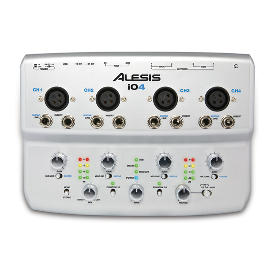
- Page 5 24. USB PORT – Use the included USB cable to connect 12. PHANTOM POWER SWITCH – Individual toggle the iO4 to a computer. iO4 requires a USB 2.0 switches activate and deactivate phantom power for connection. Note that the iO4 is not USB bus powered.
-
Page 6: Disassembly Procedures
DISASSEMBLY PROCEDURES 1. DISASSEMBLE THE CABIET(Fig1) (A)REMOVE 5 NUTS AND 5 WASHERS OF THE BACK PAEL 。 (B)REMOVE 5 SCREWS OF THE BOTTOM CHASSIS 。 (Fig1) - Page 7 2.DISASSEMBLE THE MAIN PCB ASSEMBLY . (Fig.2) (A)REMOVE 8 SCREWS 。 (B)REMOVE 8 NUTS AND 8 WASHER FROM THE TOP PANEL 。 (C)REMOVE 7 KNOB FROM THE TOP PANEL 。 (D)REMOVE 7 NUTS AND 7 WASHERS FROM THE TOP PANEL 。...
-
Page 8: Explode Diagram
EXPLODE DIAGRAM LUBAALE01/02/03/04/07 SEQUENCE NO OF EXPLODE DIAGRAM WILL BE MARKED ON REF. COLUMN OF BOM LIST... -
Page 9: Packing Diagram
PACKING DIAGRAM LUBAALE01/02/07... - Page 10 PACKING DIAGRAM LUBAALE03/04...
-
Page 11: Rubber Foot
LUBAALE01 DESCRIPTION LEVEL PT133001701 Panel-Printing(Painting) PT1330017 Panel PT1310613601 KNOB electroplate PT13106136 KNOB PT1510643 ALPHA Knob PT133032701 Bottom Plate(Painting) PT1330327 Bottom Plate SC0308PBNI Screw M3x8 PBN TAPPING AL9-23-0023 RUBBER FOOT AA812440J PW122X160X050STL PT13106140 Light Pipe PT13106141 Light Pipe(Signle) AL4-71-0016 Cable USB RF Choke 2.0 AL9-63-0050 DVDVD Cubase LE5 V5.1.1 LAC53ALE112... - Page 12 AL2-72-0339 IC LM339 ANALOG COMP SOP-14 U9,21,23,24 AL2-74-0181 IC OPTO-ISOLATOR TLP181 TRANS- AL2-75-4344 IC CS4344-CZZ 24bit 192KHz Ste U13,33 AL2-85-0403 IC TPS60403 U3,5,10 AL4-00-0002 MIDI Jack 8P 90° Female J4,5 AL4-08-0402 Con USB 4-Pin Female PC-MNT Ho AL4-15-0004 CONNECTOR 4P 2.54 180° AL6-01-0012 Switch SLIDE 2P2T AL6-02-0001...
- Page 13 PC10A015 Main PCB 4 Layer FR-4 1.6T 140 PT1304702 PLATE (J5) RS000004J06 RES 0 5% SMD 1206 R26,27 RS000010J03 RES 0 5% SMD 0603 R2,160~164,167~179,212,217,219 R299~310,317 RS000110J03 RES 1 5% SMD 0603 R33~35,84,88,143,202,203,206,329,336 RS001K10F03 RES 1K 1% SMD 0603 R9,15,16,72,73,93,94,100,101,112,113,135 R138,146,151,154,166,182,186,187,191,194 R195,200,201,208~211,216,218,220,228,229 R251,252,256,257...
-
Page 14: Variable Resistance
RSN0470104J03 RES NETWORK 470 5% 1/10W SMD R132 SWSKD22 Switch slide 2P2T 10MM S1~6,9 SWSSV-23D09N-G6 Switch Slide 2P3T SW13 TR2SD2114KSM Transistor 2SD2114K NPN SOT-23 Q1,2,18,19,23,26 TRFDD4685 MOSFET FDD4685 P-CH TO-252 UHFS4W1010-331K Capacitor 330UH L1,2 VRR50202502 VARIABLE RESISTANCE P1,2,9,10... - Page 15 MIDI PORTS MIDI IN MIDI OUT PHANTOM PWR PHANTOM PWR MIDI OUT R132C MIDI_OUT_LED_EN 470 OHM MIDI IN R132B MIDI_IN_LED_EN 470 OHM USB ACTIVITY R132A ENUM_STATUS 470 OHM POWER LED R132D INPUT 470 OHM R146 5.1k R147...
- Page 16 CH1 INPUTS CH2 INPUTS 15.0k 1% 15.0k 1% 15.0k 1% 15.0k 1% 15.0k 1% 15.0k 1% 15.0k 1% 15.0k 1%...
- Page 17 CH3 INPUTS CH4 INPUTS R283 R281 15.0k 1% 15.0k 1% R262 R234 15.0k 1% 15.0k 1% R263 R235 15.0k 1% 15.0k 1%...
- Page 26 AI02 – Akai EIE Test Procedure version 2.1 December 8 Cables and Equipment: Description Image Phantom Power Tester Midi Cable 1/4” TS Cable USB Cable Insert Cable Audio Signal Generator Setup: 1. Install MaxMSP Runtime available at www.cycling74.com 2. Plug USB Cable from iO 4 into computer 3.
- Page 27 ASIO4ALL Control Panel. Icon Looks like this: In the ASIO4ALL control panel, Be sure only the iO4 is Selected. On my computer the EIE is called “USB Audio Device”. On some machines it is called 'iO4”. Setup ASIO4ALL to look similar to this: Test #1 –...
- Page 28 3. Plug Headphones into Headphones Jack PRIOR TO PUTTING HEADPHONES DIRECTLY EARS VERIFY THE SIGNAL IS NOT TOO LOUD, IN CASE OF DEVICE FAILURE A LOUD SIGNAL MAY DAMAGE EARS** 4. Press Enter to Start Test #4 5. Move Headphone selector to 1-2. You should hear a (440HZ tone) VERIFY: Moving phones knob changes volume of headphones.
- Page 29 VERIFY: Audio Signal is no longer present 10. Remove Insert Cable from CH 2. 11. Unplug Signal generator from CH 2 and plug into CH 3. 12. Move MONO / STEREO Switch to STEREO. VERIFY: Audio signal from the audio signal generator in the Left head phone. ELSE FAIL 13.
-
Page 30: End Of Test
If both (2) LEDs on the test light, PASS. Else, FAIL. Unplug 48V tester from channel 4. Remove Device 1. Power Unit Off 2. Unplug USB 3. Plug new Unit into computer. 4. Plug USB 5. Power Unit On 6. Press Space Bar to REFRESH and start over with new unit END OF TEST...
Need help?
Do you have a question about the iO4 and is the answer not in the manual?
Questions and answers