Table of Contents
Advertisement
Quick Links
File NO.:FiiO-GCZD-2013-1-26
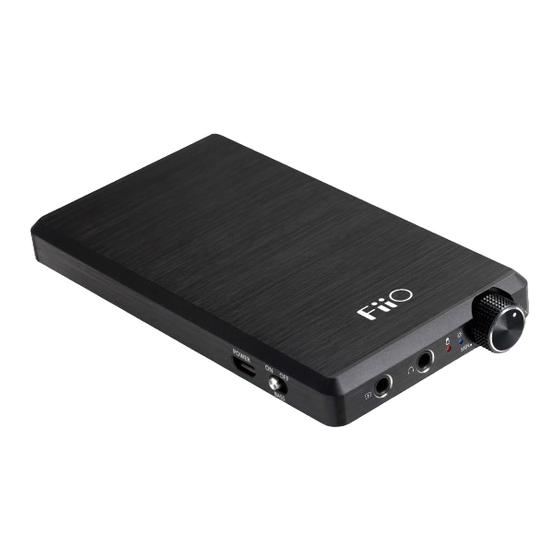
Item NO.:E12
Released by:Engineering Dept.
Readers: FiiO manufacturing dept, quality dept and FiiO official agents,users
Maintenance instruction of changing E12'S main board
In order to make customers more satisfied, speed up the procedures of
handling repaired products and reduce the both way shipping cost, so from next
year sales agents will do the board-level maintenance for the models whose value
is high and motherboard is easy to change. (Changing the motherboard instead of
changing spare parts)
This maintenance instruction is suitable for sales agents or users who will
change E12's main board .Please see following details:
Detail
Tools for disassembling E12 ("+" shape screw driver, tweezers, soldering iron)
s
1. Disassembling
Maintenance instruction
File category:[maintenance
instruction]
Code NO.:5530035
Date:2013-1-26
Advertisement
Table of Contents

Related Manuals for Fiio E12


Summary of Contents for Fiio E12
- Page 1 (Changing the motherboard instead of changing spare parts) This maintenance instruction is suitable for sales agents or users who will change E12’s main board .Please see following details: Detail Tools for disassembling E12 (“+” shape screw driver, tweezers, soldering iron) 1. Disassembling...
- Page 2 Maintenance instruction Take out two screws in backboard with a “+” shape screwdriver and then open the back board, see above pictures. Take off BASS button. Inserting into the bottom of aluminum button with tweezers and then pray it out properly. Push the stand of the main board inward properly, then take it out after pushing off.
- Page 3 Maintenance instruction 5. Use the tweezers to take left/right buckles out properly, see above pictures. 7. Wring out potentiometer nub with tweezers, and then wring out three screws of the main board, please see above pictures. 8. Take out the battery with soldering iron, and then take out the hardware chips ,see above pictures.
- Page 4 Maintenance instruction 9. Take out the silicone bond of potentiometer with tweezers, see above pictures. 10. Change the new main board and then assemble it in the opposite way. Suitable for sales agents/users to fix or change the main board. Appli catio remar...
Need help?
Do you have a question about the E12 and is the answer not in the manual?
Questions and answers