Table of Contents
Advertisement
Quick Links
Advertisement
Table of Contents

Related Manuals for Pennsylvania Scale Company MDL64 ABS


Summary of Contents for Pennsylvania Scale Company MDL64 ABS
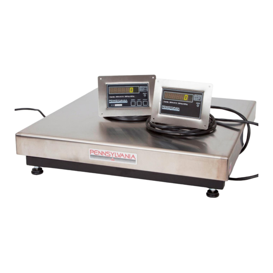
- Page 1 Page 1 of 18 MDL64 ABS Technical Manual 665 North Reservoir Street Lancaster PA 17602 P: 800.233.0473 717.295.6935 sales@pascale.com Manual MDL64TM2020REV1 For Tech Support Manuals and How To Videos go to: pascale.com/resource-library/ or email us at: sales@pascale.com...
-
Page 2: Table Of Contents
Page 2 of 18 MDL64 ABS Technical Manual Table of Contents Unpacking and Setup Specifications Display Dimensions and Load Cell and Communication Connections 5 - 6 Calibration/Configuration Access, Selecting/Changing Parameters Navigating the Menus Menu Layout Configuration Calibration Menus 9 – 14 Scale Remote Command Formats 15 –... -
Page 3: Unpacking And Setup
Page 3 of 18 MDL64 ABS Technical Manual Unpacking and Startup Unpack The Scale Electronics and Base • Gently remove scale electronics, remote displays and scale base from packaging • Plug the scale in to 110/120 VAC • If needed - connect to Scale Base with terminal connection inside the indicator enclosure. -
Page 4: Specifications
Page 4 of 18 MDL64 ABS Technical Manual SPECIFICATIONS • LOAD CELL A/D CONVERTER • TYPE: 24-bit delta sigma (1:16,777,216) • EXCITATION: 5 VDC, 120 mA max. • SIGNAL INPUT: 16 mv • SENSITIVITY: 0.1 Uv/grad • UPDATE RATE: 30 update/second •... -
Page 5: Display Dimensions And Load Cell And Communication Connections
Page 5 of 18 MDL64 ABS Technical Manual Display Housing Dimensions For Tech Support Manuals and How To Videos go to: pascale.com/resource-library/ or email us at: sales@pascale.com... - Page 6 Page 6 of 18 MDL64 ABS Technical Manual Connections: RS‑232 PIN ASSIGNMENTS AND IMPLEMENTED FUNCTIONS Connection to the Serial Port is made via a DB‑9 female connector found in the access area under the scale. Internal Instrument connection is on the main board, TB2-1,2,3.
-
Page 7: Calibration/Configuration Access, Selecting/Changing Parameters Navigating The Menus
Page 7 of 18 MDL64 ABS Technical Manual Calibration/Configuration Access, Selecting/Changing Parameters Navigating the Menus To access instrument configuration, calibration: ZERO Press and Hold the ZERO button for 5 seconds - 5 seconds X] are The Audit Trail counters [... -
Page 8: Menu Layout
Page 8 of 18 MDL64 ABS Technical Manual Menu Layout CAL 20 Capacity, Resolution, Zero Range, Units, Print, Overrange, Zero Tracking CAL 30 Secondary Resolution and Setup CAL 40 Filter Settings, Load Cell Zero/Deadload and Span Calibration CFG 60 RS232 Configuration: Baud Rate, Word, Stop, Parity, Echo, Address... -
Page 9: Configuration Calibration Menus
Page 9 of 18 MDL64 ABS Technical Manual Configuration Calibration Menus PRINT CAL 20 Calibration setting entry point. Use to enter this menu and enter selections STEP Parameter Description CAP 21 Full capacity of the scale Standard capacities are 2, 5, 10, 20, 50, 100, 150 and 200 lbs. - Page 10 Page 10 of 18 MDL64 ABS Technical Manual CAL 30 Secondary units, resolution. Use to enter this menu and enter selections STEP Parameter Description 2Un 31 1, 2, 3, 4, 5, 6, 7, 8, 9, Select the secondary weighing unit by...
- Page 11 Page 11 of 18 MDL64 ABS Technical Manual CAL 40 Load Cell Calibration. Use to enter this menu and enter selections STEP Parameter Description FIL 41 1-15 Response time: 0-9 selects conversions to average directly. 11-15 correspond to 25, 30, 35, 40, & 50 conversions for extended filtering.
- Page 12 Page 12 of 18 MDL64 ABS Technical Manual PRINT CFG 60 RS-232 Port Configuration. Use to enter this menu and enter selections STEP Parameter Description Bau 61 300,600,1200,2400, Baud Rate Setting. Use ZERO button to select. 4800, 9600, 19200, 38400...
- Page 13 Page 13 of 18 MDL64 ABS Technical Manual CAL 80 Programmable data output. Use to enter this menu and enter selections Building a programable data output. The user programmable data output feature is the string of information sent from the RS-232 port (Or optional Ethernet, Wi-Fi and USB) when the PRINT button is pressed, scale is setup to auto output or the scale receives an SRP command from a computer or terminal.
- Page 14 Page 14 of 18 MDL64 ABS Technical Manual Data Output Codes Data Output Description Data Output Description Code Code OPTIONAL time OPTIONAL date Unit of measure suffix label “Gross” prefix “Tare” prefix “Net” prefix FR”F1” for use with Barcode ? symbol used with Barcode...
-
Page 15: Scale Remote Command Formats
Page 15 of 18 MDL64 ABS Technical Manual NOTE: After PSL 119 or after data output code 99 the display will show Set.rSd. which is a PRINT feature not available on the MDL64. To skip press the button Scale Remote Command Formats... - Page 16 Page 16 of 18 MDL64 ABS Technical Manual Remote Scale Commands Which Request Information Command Description Response Format Send Gross Weight, 7600 only Gross(sp)XXXXXXX(cr)(lf) Send Metrological or Load Cell Calibration Information Send Net Weight Net(sp)XXXXXXX(cr)(lf) Send Data Output Codes Send Formatted Data Output...
-
Page 17: Scale Status And Error Codes
Page 17 of 18 MDL64 ABS Technical Manual Scale Displayed Status and Error Messages Error Message Description D/A card detected - Displayed under the check function. IIC.ERR IIC short - Power-up hardware failure indication. Displayed on power-up when the DC power push-button is pressed. -
Page 18: Replacement Parts List
Page 18 of 18 MDL64 ABS Technical Manual Replacement Parts List Part No: Description Notes (1) Buttons ZERO/UNITS/PRINT Complete DISPLAY assembly Specify GREEN LED’s (standard) or RED LED displays. (1) NO BUTTONS for customer side 59266-2 Includes SS bezels, display assys., Y-cable – all items.
Need help?
Do you have a question about the MDL64 ABS and is the answer not in the manual?
Questions and answers