Table of Contents
Advertisement
Quick Links
MODEL MLX-9X04 series
HARLEY J1850 SPEEDOMETER/TACHOMETER
.
Please read this before beginning installation or wiring
IMPORTANT NOTE!
This gauge has an odometer preset option that is only available one time
within the first 100 miles (160 km) of operation. See ODOMETER PRESET MENU for instructions.
MAN #650777
Advertisement
Table of Contents

Subscribe to Our Youtube Channel
Related Manuals for Dakota Digital MLX-9X04 Series


Summary of Contents for Dakota Digital MLX-9X04 Series
- Page 1 MODEL MLX-9X04 series HARLEY J1850 SPEEDOMETER/TACHOMETER Please read this before beginning installation or wiring IMPORTANT NOTE! This gauge has an odometer preset option that is only available one time within the first 100 miles (160 km) of operation. See ODOMETER PRESET MENU for instructions.
-
Page 2: Wiring Diagram
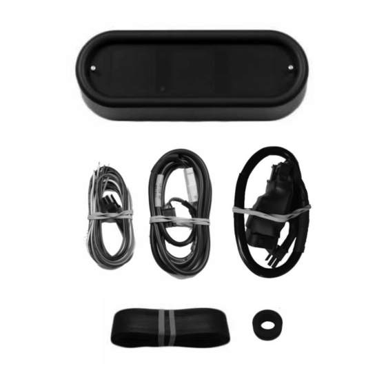
MOUNTING A mounting bracket must be purchased for your application. Any BKT-50xx series bracket may be used. The bar mount brackets can be used for above-the-bar mounting or below-the-bar mounting. The 35° triple-tree mounts are only available for above-the-bar mounting. The triple-tree mounting bracket replaces the original handle bar mount. The gauge attaches to the back side of the bracket with the supplied screws. -
Page 3: Night Dimming
OPTIONAL OIL PRESSURE Dakota Digital part number SEN-1039 must be used. The sensor red wire connects to the indicator harness white/red wire, the sensor white wire connects to the gauge gray wire, and the sensor black and bare shield wires connect to the indicator harness black wire. -
Page 4: System Features
System features INDICATORS Left turn Check engine Low oil Right turn Light sensor (green) (red) (red) (green) (red) High beam Neutral Security (blue) (green) (red) INFORMATION DISPLAYS There are 5 reading locations available to display information. They are labeled LEFT TOP, LEFT BTM, CENTER, RIGHT TOP, RIGHT BTM, respectively. - Page 5 Operation, Clock Set, Service Reset FUNCTION SWITCHES The two switches built into the face of the gauge allow you to make adjustments to the gauge. During normal operation, the function switch allows access to information including mileage, RPM, and performance data located within the 4 outer display locations.
-
Page 6: Setup Menu
Programming SETUP MENU *To simplify the setup procedure, The function switch is used to enter setup mode. To get into setup, press and hold either switch while turning the key on. Another option to enter SETUP is to press and hold both switches while the system is powered. Press and release the switch to advance through the menus below, press and hold to enter each menu. -
Page 7: Exiting Setup
FUEL Enable/Disable option fuel level reading SENDER HD 2004 HD 2008 DYNA 04 DYNA 08 CUSTOM Program custom fuel curve FAT BAGGER SPORTSTER RANGE TO EMPTY LEARN RESET DISPLAY Display will show a fill bar for fuel reading DIGITAL Display will show a percentage reading for fuel TEST Display sender resistance for troubleshooting BACK... - Page 8 LIGHTING Lighting menu for color changes When The color menu options are: COLOR DISPLAY COLOR LABEL COLOR MESSAGE COLOR BAR COLOR DIMMING SUNLIGHT BACK Since the color options are so expansive the selection process is the same in all sections. Press and release the switch to change the selection.
- Page 9 , and release. The display options are SEN-1043 SEN-1044 Press and release the switch to match to the optional sender you purchased from Dakota Digital. Press and hold the switch on the selection, , and release. HIGH WARNING High oil temperature warning setup When >...
- Page 10 OIL PSI Engine oil temperature setup menu Only valid when optional SEN-1039 pressure sender is purchased from Dakota Digital. When >OIL PSI press and hold either is displayed, and release. press and hold the switch is displayed, and release. The selections will be...
- Page 11 Filling and refilling must be done the same way, either both on kick stand or both upright. TEST Gauge reading test TEST Exit setup. DISPLAYS Message display option menu Refer to graphic on page 7 for indicator and message locations. When >DISPLAYS either switch until , and release.
-
Page 12: Factory Reset
VOLT Low voltage warning setup When > press and hold either displayed, and release. The low voltage warning points will range from 9.0 to 12.1 volts. Press and release the switch to change the low voltage warning point. Press , and release. Exit setup. -
Page 13: Troubleshooting Guide
Troubleshooting guide Problem Possible cause Solution Gauge will not light up. Brown/Gray wire does not have power. Inspect and repair stock harness. Orange/White wire does not have power. Inspect and repair stock harness. Orange wire does not have power. Inspect and repair stock harness. Black wire is not getting a good ground. -
Page 14: Service And Repair
SERVICE AND REPAIR DAKOTA DIGITAL offers complete service and repair of its product line. In addition, technical support is available to help you work through any questions or problems you may be having installing one of our products. Please read through the Troubleshooting Guide. There, you will find the solution to most problems.
Need help?
Do you have a question about the MLX-9X04 Series and is the answer not in the manual?
Questions and answers