Table of Contents
Advertisement
Quick Links
Advertisement
Table of Contents

Related Manuals for Technisonic Industries Limited ACCESS/A A710X


Summary of Contents for Technisonic Industries Limited ACCESS/A A710X
- Page 1 ACCESS/A EXPANSION PANEL MODELS: A710X & A711X Installation and Operating Instructions TiL Document No. 06RE387 rev-A April 2007 Technisonic Industries Limited 240 Traders Blvd. E., Mississauga, Ontario L4Z 1W7 Tel:(905)890-2113 Fax:(905)890-5338 www.til.ca...
- Page 2 ACCESS/A A710X/A711X Installation & Operating Instructions 06RE387 rev. B REVISIONS Revision Page Description Date Approved compliance reference changed Jun 21 2007 from TSO-C50c to TSO-C139 Added TSO installation notification Nov. 11/10 Technisonic Industries ltd. Copyright 2007 BY TiL ALL RIGHTS RESERVED...
- Page 3 ACCESS/A A710X/A711X Installation & Operating Instructions 06RE387 rev. B WARRANTY INFORMATION The Models A710X and A711X Audio Expansion Panels are under warranty for one year from date of purchase. Failed units caused by defective parts or workmanship should be returned for warranty...
-
Page 4: Table Of Contents
ACCESS/A A710X/A711X Installation & Operating Instructions 06RE387 rev. B TABLE OF CONTENTS SECTION 1 GENERAL DESCRIPTION Introduction ........................1-1 Description .........................1-1 Purpose of Equipment ....................1-2 Model Variation ......................1-2 Technical Summary ....................1-5 System Limitations .....................1-7 SECTION 2 INSTALLATION INSTRUCTIONS General ........................2-1 Equipment Packaging Log ..................2-1 Wiring Requirements ....................2-1... - Page 5 ACCESS/A A710X/A711X Installation & Operating Instructions 06RE387 rev. B LIST OF TABLES A710X General Specifications ..................1-5 A711X General Specifications ..................1-6 LIST OF ILLUSTRATIONS A710X Expansion Panel - General View ............... 1-3 A711X Expansion Panel - General View ............... 1-4 2-1A A710X Outline Drawing ....................
-
Page 6: General Description
INTRODUCTION This publication provides operating and installation information on the Model A710X and A711X, ACCESS/A Audio Expansion Panels manufactured by Technisonic Industries Limited. These units are designed to provide six additional communications channels to either the Model A710 or A711 ACCESS/A audio controllers. The A710X unit may be directly interchanged with an A711X in the same harness, but the units are physically different in size, and the A711X has individual volume controls for the receiver monitor levels. -
Page 7: Purpose Of Equipment
ACCESS/A A710X / A711X Installation & Operating Instructions 06RE387 rev. B PURPOSE OF THE EQUIPMENT The A710 and A711 ACCESS/A Audio Controllers are able to directly access a maximum of seven transceivers. Connecting an A710X or A711X Expansion Panel to the ACCESS/A controller will increase this capability to a maximum of thirteen transceivers. - Page 8 ACCESS/A A710X / A711X Installation & Operating Instructions 06RE387 rev. B FIGURE 1-1 A710X ACCESS/A EXPANSION PANEL - GENERAL VIEW Technisonic Industries ltd. Copyright 2007 BY TiL ALL RIGHTS RESERVED Page 1-3...
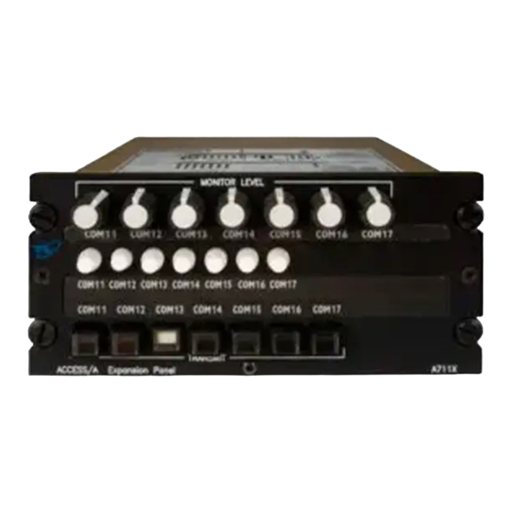
- Page 9 ACCESS/A A710X / A711X Installation & Operating Instructions 06RE387 rev. B FIGURE 1-2 A711X ACCESS/A EXPANSION PANEL - GENERAL VIEW Technisonic Industries ltd. Copyright 2007 BY TiL ALL RIGHTS RESERVED Page 1-4...
-
Page 10: Technical Summary
ACCESS/A A710X / A711X Installation & Operating Instructions 06RE387 rev. B TECHNICAL SUMMARY A summary of the relevant electrical, operational, mechanical and physical characteristics of the expansion panels are given in Table 1-1 and 1-2, General Specifications. TABLE 1-1 A710X GENERAL SPECIFICATIONS... -
Page 11: A711X General Specifications
ACCESS/A A710X / A711X Installation & Operating Instructions 06RE387 rev. B TABLE 1-2 A711X GENERAL SPECIFICATIONS MODEL A711X - ACCESS/A Expansion Panel: PHYSICAL CHARACTERISTICS: Width (max.) ........................5.75 inches Height (max.) ........................2.625 inches Depth ..........................6.07 inches Weight ........................2.0 lbs. (0.91 Kg) Mounting .................... -
Page 12: System Limitations
ACCESS/A A710X / A711X Installation & Operating Instructions 06RE387 rev. B SYSTEM LIMITATIONS A summary of the relevant system limitations is given below. Induced Signal Susceptibility, RF Susceptibility and RF Emission The wiring connections called out in the Installation and Operating Instructions, chapter 2, describes shield terminations for minimum ground loop noise. -
Page 13: Installation Instructions
ACCESS/A A710X / A711X Installation & Operating Instructions 06RE387 rev. B SECTION 2 INSTALLATION INSTRUCTIONS GENERAL This section contains information and instructions for the correct installation of the A710X and A711X, ACCESS/A Expansion Panels. Make certain that the unit is correctly operating in accordance with the equipment user's requirements and manufacturer’s specifications, prior to releasing the equipment for service. -
Page 14: Cable Clearance
ACCESS/A A710X / A711X Installation & Operating Instructions 06RE387 rev. B CABLE CLEARANCE: Allow at least 2.5” of additional rear clearance for mating connectors and hoods (side routing), or 3.0” (back routing). Cables should be long enough to permit the unit to be removed from the panel, and the connectors to be easily disengaged. - Page 15 ACCESS/A A710X / A711X Installation & Operating Instructions 06RE387 rev. B FIGURE 2-1A Outline Drawing for Model A710X ACCESS/A Expansion Panel Technisonic Industries ltd. Copyright 2007 BY TiL ALL RIGHTS RESERVED Page 2-3...
- Page 16 ACCESS/A A710X / A711X Installation & Operating Instructions 06RE387 rev. B FIGURE 2-1B Outline Drawing for Model A711X ACCESS/A Expansion Panel Technisonic Industries ltd. Copyright 2007 BY TiL ALL RIGHTS RESERVED Page 2-4...
- Page 17 ACCESS/A A710X / A711X Installation & Operating Instructions 06RE387 rev. B Shields are grounded as required at either end of the cables. Do not ground both ends of a shield. Mic/Key/Lo lines may be run as a 3-cond. shielded wire in noisy environments for better RF rejection.
- Page 18 ACCESS/A A710X / A711X Installation & Operating Instructions 06RE387 rev. B Shields are grounded as required at either end of the cables. Do not ground both ends of a shield. Mic/Key/Lo lines may be run as a 3-cond. shielded wire in noisy environments for better RF rejection.
- Page 19 ACCESS/A A710X / A711X Installation & Operating Instructions 06RE387 rev. B Shields are grounded as required at either end of the cables. Do not ground both ends of a shield. Mic/Key/Lo lines may be run as a 3-cond. shielded wire in noisy environments for better RF rejection.
-
Page 20: Installation Kit Contents
ACCESS/A A710X / A711X Installation & Operating Instructions 06RE387 rev. B INSTALLATION KIT - CONTENTS The IN-A710X installation kit (used for both A710X & A711X units) consists of: One 50 pin female D-subminiature mating connector complete with crimp pins, V-locks and hood. (DD50S) P101 Positronics p/n SD50F00JVLX + 50ea. -
Page 21: Pin Locations And Connections
ACCESS/A A710X / A711X Installation & Operating Instructions 06RE387 rev. B INSTALLATION - PIN LOCATIONS AND CONNECTIONS The pin numbers and locations for the connectors located on the rear of the A710X/A711X ACCESS/A Expansion Panel are shown in the following tables. - Page 22 ACCESS/A A710X / A711X Installation & Operating Instructions 06RE387 rev. B Mating DC37S Top Connector J211 DC37P Cable Connector: (37 Pin Female) J211 Connector Pin Assignments - RX Connector Connection HIGH Notes SUM Out To Audio Panel RX COM channel Shield ground Shield drain for input lines.
-
Page 23: Main Power
ACCESS/A A710X / A711X Installation & Operating Instructions 06RE387 rev. B MAIN POWER +28VDC The main power +28VDC (±20%) is connected to pin 17 of the 50 pin (lower) "D" connector. As previously indicated, this connection should be made with at least #24 AWG wire, with #22 preferred. -
Page 24: Front Panel Operators Switches And Controls
ACCESS/A A710X / A711X Installation & Operating Instructions 06RE387 rev. B SECTION 3 OPERATING INSTRUCTIONS FRONT PANEL OPERATORS SWITCHES AND CONTROLS This section explains the operation of the A710X & A711X ACCESS/A Expansion Panel Controls, and how to use either system in a typical aircraft environment. Since the controls on the two units differ only in the extra receive monitor pots at the top of the A711X, the A710X illustration is used for all of the explanations, except those specific to the A711. -
Page 25: Rx Or Receive Selectors
ACCESS/A A710X / A711X Installation & Operating Instructions 06RE387 rev. B 3.1.1 RX or RECEIVE SELECTORS These 10 push-button RX SELECTOR switches allow the crew to monitor any combination of the Receivers in the airframe system, independent of the setting of the transceiver selectors. The RX SELECTORS have an alternate action, push in to activate the audio, push again to have the switch return to the out position and off. -
Page 26: A711X Rx Monitor Level Controls
ACCESS/A A710X / A711X Installation & Operating Instructions 06RE387 rev. B 3.1.3 A711X RX MONITOR LEVEL CONTROLS The operation of the A711X control differs slightly from the A710X, in that individual receive monitor controls are provided to adjust the level for each of the 7 transceivers. These controls normally go to approximately 2-5% level at the minimum setting (not off), but can be strapped internally to go fully off, if required. -
Page 27: Special Signal Considerations
ACCESS/A A710X / A711X Installation & Operating Instructions 06RE387 rev. B SPECIAL SIGNAL CONSIDERATIONS There are several special signals and lines related the A710 and A711, which require careful installation planning, and understanding by the flight crew. 3.2.1 SUM NODE This line is used to expand the RX input bus of the A710/A711 control, and allows many supplemental receivers to be attached with high isolation from other signals. -
Page 28: Changing Overlay Lighting & Radio Legends
ACCESS/A A710X / A711X Installation & Operating Instructions 06RE387 rev. B CHANGING OVERLAY LIGHTING & RADIO LEGENDS The legends on the A710X and A711X front panels, and the overlay color and lighting type can all be easily changed in the field to suit special requirements. The entire lighted overlay is changed by removing three screws, as illustrated below.
Need help?
Do you have a question about the ACCESS/A A710X and is the answer not in the manual?
Questions and answers