
Related Manuals for Atest Gaz Sigma MOD LCD


Summary of Contents for Atest Gaz Sigma MOD LCD
- Page 1 User Manual Control Unit Module Sigma MOD LCD Product code: PW-033-B POD-003-ENG R04...
- Page 2 We design, manufacture, implement and support: Systems for Monitoring, Detection and Reduction of gas hazards We invite you to familiarize yourself with our offer on www.atestgaz.pl Atest Gaz A. M. Pachole sp. j. ul. Spokojna 3, 44-109 Gliwice Poland tel.: +48 32 238 87 94 fax: +48 32 234 92 71 e-mail: contact@atestgaz.pl...
-
Page 3: Table 1: Optical Indicators Status Notation
www.atestgaz.pl Remarks and reservations Connection and operation of the device is allowed only after reading and understanding the contents of this document. Keep User's Manual with the device for future use. The manufacturer bears no responsibility for errors, damages and failures caused by improper selection of devices and cables, improper installation or failure to understand the contents of this document. -
Page 4: Table Of Contents
www.atestgaz.pl Table of contents 1 Preliminary information..........................6 1.1 General description..........................6 1.2 Operation principle..........................8 1.3 Device characteristics..........................8 2 Input-output interfaces...........................9 2.1 Relays output R1 – R8..........................10 2.2 Binary inputs DI 1 – DI 4........................12 2.3 SBUS communication port........................13 2.4 ExBUS communication port – data gateway, External Data Inputs............14 2.5 Polarity of communication lines......................15 3 User interface............................15 3.1 Front panel............................15... - Page 5 List of figures Figure 1: Application of the Control Unit Module Sigma MOD LCD..............7 Figure 2: Example of collaboration between the Sigma MOD LCD device and ambient environment..7 Figure 3: Electric connections........................9 Figure 4: Galvanic separation between various interfaces of the control unit module – structural diagram 9 Figure 5: Relays in active and inactive state....................10...
-
Page 6: Preliminary Information
Gas Safety Systems have been used for many years for continuous monitoring of ambient atmospheres and detection of hazardous gases. The Sigma MOD LCD described in this manual is part of the Gas Safety System Sigma Gas, a comprehensive solution for safety of hazardous environments. The system includes the following components: gas detectors –... -
Page 7: Figure 1: Application Of The Control Unit Module Sigma Mod Lcd
Sigma Bus data Digital input Relay outputs transmission bus Area covered by a system for gas concentration monitoring Figure 2: Example of collaboration between the Sigma MOD LCD device and ambient environment s. 7|40 User Manual: POD-003-ENG R04... -
Page 8: Operation Principle
Operation principle The Control Unit Module Sigma MOD LCD scan statuses of detectors connected to the gas monitoring system and read their indications. That information is depicted by means of indicating LEDs. The measured values of gas concentration as well as other special signals (e.g. defects) are used to control relay outputs of the unit. -
Page 9: Input-Output Interfaces
Some interfaces are galvanic separated from each other. The idea is shown on the structural diagram below. DI input Power Supply SBUS, EXBUS Sigma MOD LCD Figure 4: Galvanic separation between various interfaces of the control unit module – structural diagram s. 9|40 User Manual: POD-003-ENG R04... -
Page 10: Table 2: Electric Interface Description
www.atestgaz.pl Name Terminal Description Power Device supply port. Parameters – see section 5.5 Negative. Both terminals „GND” are internally connected Positive. Both terminals „+” are internally connected Binary input, see section 2.2 1 – 4 DI1 – DI4 inputs Common terminal of DI input Line polarity Configuration jumpers for the SBUS port. - Page 11 230V for the valve – without a tests of the valve control line (3 impulses 1 second long with 1 second of interruption). Below describe default setting for Sigma MOD LCD: Output No.
-
Page 12: Binary Inputs Di 1 - Di 4
www.atestgaz.pl Table 3: Default configuration of relay outputs The desired configuration of outputs R1 – R8 must be specified upon submission of the order (the outputs are configured by the manufacturer at the factory workshop). Gas concentration 1 warning threshold Button Output R4 time... -
Page 13: Sbus Communication Port
www.atestgaz.pl specific inputs (see Section 5.5), these inputs can be considered as two logic levels. Current status of these inputs can be viewed on the user interface (see Section 3.1.2). These inputs are galvanic separated from other circuits of the device, although no galvanic separation between individual inputs is provided (see Figure 14). -
Page 14: Exbus Communication Port - Data Gateway, External Data Inputs
ExBUS communication port – data gateway, External Data Inputs The Control Unit Module Sigma MOD LCD comprise a communication port called ExBUS designed for exchange of information between the Sigma Gas system and external environment (e.g. PLCs, SCADA, etc.). -
Page 15: Polarity Of Communication Lines
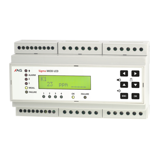
Polarity of SBUS and ExBUS ports active 5,6kΩ 5,6kΩ 5,6kΩ Table 6: Configuration of polarity for SBUS and ExBUS ports User interface Front panel ALARM K12 Pomp-H2 12.6 %LEL _▄█__ MEAS. FAILURE FAILURE Figure 10: Sigma MOD LCD front panel s. 15|40 User Manual: POD-003-ENG R04... -
Page 16: Device Status Area
www.atestgaz.pl Sigma MOD DO front panel includes: 1. device status area, 2. status area for digital inputs DI, 3. status area for gas detectors, 4. LCD display area, 5. keypad area. All these areas as described with details in subsequent sections. 3.1.1 Device status area Indicators in that area are meant to depict current status of the Control Unit Module. -
Page 17: Lcd Display
www.atestgaz.pl 3.1.4 LCD Display The display is meant for the following purposes: show statuses of detectors connected to the control unit, values of gas concentration measured by these detectors and auxiliary details related to detectors (designation of the monitoring location, units for gas concentration, etc.), show system messages and menu items. -
Page 18: Figure 11: Map Of The Control Unit Interface
www.atestgaz.pl Detector View Erase 1.History menu history history Controller start Alarm Alarm 2.Detector Type, Thresholds Threshold info Range Down User interface Self-test 3.Locked Address, Active Agent Operation Detector Serial (CAS No.) Time Reset number 4.Zero level Home tuning screen Short hit simultaneously 5. -
Page 19: Control Unit Start Up, Interface Self-Test
www.atestgaz.pl Navigation within the interface and adjustment of available options is possible owing to a keypad. Unless specified otherwise, the following rules apply to all menu operations. pushbuttons are used in line with the specifications outlined in Section 3.1.5, blinking messages on the display (except for the home screen) highlight the locations where a decision must be taken by an operator /user (e.g. -
Page 20: Home Screen
www.atestgaz.pl It is recommended to run the user interface test at least once a week to make sure that all LED indicators and the buzzer are in sound operating condition. Home screen The home screed comprises several fields. K12 Pump-H2 HIS 12.6 %LEL _▄█__L Figure 12: Specific fields of the home screen Field No. -
Page 21: General Code Of Indications
www.atestgaz.pl For the home screen the Control Unit Module periodically displays information for all channels, where channels are switched over every three seconds. Alternatively, an operator can scroll scanning of channels manually by depressing the right or left arrow buttons on the keypad (see Section 3.1.5), Upon each depressing the Control Unit Module holds content for the specific channel for 15 seconds and then moves to the subsequent channel. -
Page 22: Indication Of Detector Statuses - Special Statuses
www.atestgaz.pl Situation Description Indicators Display / buzzer Alarm The gas concentration exceeds the second K12 Pump-H2 warning threshold. ALARM 29.3 %LEL ___▄█ Indicators 1, 2 and ALARM on the front panel are continuously on and the internal buzzer is activated (can be muted by means MEAS. - Page 23 www.atestgaz.pl Situation Description Indicators Display / buzzer Test The detector is in the calibration mode. Its K12 Pump-H2 indications are merely simulated but all ALARM 17.9 %LEL Test signals received by the control unit are considered as valid ones. Gas alarms and failure signals are allowed.
-
Page 24: Response To Gas Concentration
www.atestgaz.pl Situation Description Indicators Display / buzzer „Inhibit” mode The detector is temporarily excluded from K12 Pump-H2 the system. Flags related to that detector ALARM „Inhibit” mode are ignored by the controller. All indicators blink twice at the same time with the interval of 30 s (_∏_∏_____). -
Page 25: Buzzer - Internal Acoustic Warning /Alarm Device
www.atestgaz.pl concentration Overload ALARM Warning 2 Warning 1 time ALARM MEAS. ALARM MEAS. The gas concentration is falling, with overload disappears warnings Description Sensor lock – sensor off, the last measurement latched Figure 13: Indications of LEDs on the front panel versus gas concentration measured by the detector Buzzer –... -
Page 26: Access Rights To The Menu Options - Login/Logout Procedures
www.atestgaz.pl buzzer is restarted (reactivated). In addition, any new gas alarm or a system defect /error that are reported during the time when the buzzer is off are capable of the buzzer reactivation. Upon disappearing of the triggering signal the buzzer goes off. The buzzer can be deactivated by means of the keypad (see section 3.1.5), DI input (see section 2.2) and External DI input (see section 2.4). -
Page 27: Detector Menu
www.atestgaz.pl level 1 (authorized operator, password protected) – enables such operations as reset of locked detectors, level 2 (maintenance, password protected) – enables adjustment of the system parameters. The default level is the basic one (level 0). All users who have physical access to the control unit and can operate with the interface are granted with the level 0 access rights. -
Page 28: History
www.atestgaz.pl Field No. Description Number of the currently selected option within the menu segment /total number of options within the menu segment. Identification of the currently selected option. Table 15: Assignment of menu fields on the LCD display Options that are selected for a specific channel affect operation of the detector connected to that channel. To select desired options for a specific channel proceed in the following way: 1. -
Page 29: Detector Info
www.atestgaz.pl Left and right arrow buttons , make it possible to change the channel assigned to information currently presented on the display, although switching between channels is limited solely to such channels where any events are recorded. However, if a channel with no events recorded in the memory of events is selected within that menu option, the following message shall be displayed: Pump H2 Chan. -
Page 30: Tuning Of The Detector Zero Level
www.atestgaz.pl The operation is only possible when a detector is locked (see Section 3.4.4). If so, the Control Unit Module can send a command to unlock (reset) the specific detector. Results of such an operation are described in Section 3.9. Prior to use the option please consult the documentation of the SmArtGas 4 detector to learn about preconditions and the unlock (reset) procedure. -
Page 31: Inhibit" Mode
www.atestgaz.pl 1. Concentration level for the 1 warning, ‘upward’ direction, 2. Concentration level for the 2 warning, ‘upward’ direction, 3. Concentration level for the alarm, ‘upward’ direction, 4. Concentration level for the 1 warning, ‘downward’ direction, 5. Concentration level for the 2 warning, ‘downward’... -
Page 32: Logout
Makes it possible to log out (switching to the basic level of authorization rights). See Section 3.6 Device menu The menu comprises options related to operation of the Control Unit Module Sigma MOD LCD and the entire Sigma Gas system. Display appearance for that screen is described in Section 3.7. 3.8.1 Device info Authorization level required for the operation 0 –... -
Page 33: Password Change For Level 2
www.atestgaz.pl Enter new password: 0*** Then the new password must be re-entered and confirmed: Confirm new password: 0*** The password for the 1 level of authorization must be changed with due care. When the password is lost, the new password for Level 1 access rights can be only changed from the Level 2 authorization or by a service division of the manufacturer. -
Page 34: Gateway Settings
www.atestgaz.pl The entered muting time is accepted by depressing the button and then the new timing parameter can be entered. Upon the last parameter is set up, all timings are stored into the controller memory. 3.8.6 Gateway settings Authorization level required for the operation 2 – Maintenance staff Specification Makes it possible to change parameters of the built-in gateway (GTW) -
Page 35: System Architectures
Control Unit Modules may vary according to actual needs. If needed, both Sigma MOD DRV and Sigma MOD LCD controllers can be combined within a system. 1 – 32 SmArtGas 4 Gas Detectors Figure 17: Example of system architecture The control unit module located at the far end of the data bus can be used with a limited scope of functionalities –... -
Page 36: Other Information
Local Authority, waste disposal companies and in the place of purchase. The equipment can also be returned to the manufacturer. Product marking Product code Device PW-033-B Sigma MOD LCD Control Unit Module s. 36|40 User Manual: POD-003-ENG R04... -
Page 37: Technical Specification
www.atestgaz.pl Technical specification Power supply • Voltage V 10 – 34 V • Power 2.5 W Environment • Ambient temperatures Ta -10 – +50°C (see point 3.1.4) • Humidity 10 – 90% long term, without condensation IP20 Digital input parameters •... -
Page 38: Dimension
www.atestgaz.pl Dimension Dimension in mm. Figure 18: Dimension of device s. 38|40 User Manual: POD-003-ENG R04... -
Page 39: Configuration
www.atestgaz.pl Configuration Serial no.: Product revision: Gas detector addresses: SBUS port ExBUS port Protocols and parameters: address: address: ASCII, 19200 7E1 ......... Output Default setting Configuration on customer's request (according to the manual) WARNING 1 WARNING 2 ALARM VISUAL ALARM (locked) SOUND ALARM MEASUREMENT SERVICE... -
Page 40: Appendices
www.atestgaz.pl Appendices DEZG017-ENG – EU Declaration of Conformity – Sigma MOD LED, LCD, DO PU-Z-003-ENG – Guidelines to the cabling of the system with an RS-485 interface PU-Z-005-ENG – Sigma Gas system – wiring diagram PU-Z-006-ENG – The memory map for the GTW functionality in Control Unit Modules Sigma MOD LCD, Sigma MOD LED, Sigma MOD DO s. - Page 41 EU Declaration of Conformity Atest Gaz A. M. Pachole sp. j. declares with full responsibility, that the product: (Product description) (Trade name) (Type identifier or Product code) Control Unit Module Sigma MOD LED PW-033 Sigma MOD LCD Sigma MOD DO complies with the following Directives and Standards: in relation to Directive 2014/30/EU –...
- Page 42 www.atestgaz.pl Guidelines to the cabling of the system with an RS-485 interface Introductory It is recommended that all system components are made according to the design created by person with the necessary skills and competence. Connection cable The data transmission line for the gas detectors working in the RS-485 standard should be performed only with the use of a shielded twisted pair cable.
- Page 43 www.atestgaz.pl Power supply of the gas detector As a standard, in gas detectors with digital data transmission, it is assumed that the voltage cannot drop below 12 V (see the documentation of the detector). The power consumption of the detector is constant within the range of acceptable voltages.
- Page 44 www.atestgaz.pl Sigma Gas system – wiring diagram Atest-Gaz A. M. Pachole sp. j. tel.: +48 32 238 87 94 p. 1/1 Appendix: PU-Z-005-ENG R01 ul. Spokojna 3, 44-109 Gliwice, Poland fax: +48 32 234 92 71 VAT No.: PL 9691433231 e-mail: contact@atestgaz.pl •...
- Page 45 Status of control unit 40068 – 40099 Temperature in measuring head of detectors at channels 1 – 32 43501 – 43503 Interface for execution of operator commands (available only for Sigma MOD LCD) 44001 – 44002 External DI control inputs Detectors' statuses (read-only) Channel No.
- Page 46 www.atestgaz.pl Flag Description Test Test mode Warm_Up Sensor's warm up Sensor_Inhibit Inhibit mode Comm_Error Error of communication with a detector Calibration_Warning Calibration time exceeded (non-critical error) Monitoring Measurement in progress System_Stop The system is stopped N – gas concentration. The value of 0 corresponds to zero concentration whilst the value of 1000 corresponds to the concentration equal to the measurement range of the detector.
- Page 47 www.atestgaz.pl Temperature in measuring head of detectors (read-only) Channel no. Register Name Description Type 40068 Temp. Temperature in measuring head 40069 Temp. Temperature in measuring head 40099 Temp. Temperature in measuring head External DI control inputs (read / write) Register Name Description Type / range...
- Page 48 Interface for execution of operator commands (read /write; available only for Sigma MOD LCD) Register Name Description Type /range 43501 Command_Status Current status of the command execution Write – data byte is ignored Read – status, the available values are: •...
- Page 49 www.atestgaz.pl Notes...
- Page 50 www.atestgaz.pl Notes...
- Page 52 Atest Gaz A. M. Pachole sp. j. Spokojna 3, 44-109 Gliwice tel.: +48 32 238 87 94 fax: +48 32 234 92 71 e-mail: contact@atestgaz.pl For more details on our devices and other products and services offered by us, visit:...
Need help?
Do you have a question about the Sigma MOD LCD and is the answer not in the manual?
Questions and answers