
Related Manuals for Atest Gaz Sigma MOD LED


Summary of Contents for Atest Gaz Sigma MOD LED
- Page 1 User Manual Control Unit Module Sigma MOD LED / Sigma MOD DO Product code: PW-033-A / PW-033-C POD-002-ENG R03...
- Page 2 We design, manufacture, implement and support: Systems for Monitoring, Detection and Reduction of gas hazards We invite you to familiarize yourself with our offer on www.atestgaz.pl Atest Gaz A. M. Pachole sp. j. ul. Spokojna 3, 44-109 Gliwice Poland tel.: +48 32 238 87 94 fax: +48 32 234 92 71 e-mail: contact@atestgaz.pl...
-
Page 3: Table 1: Optical Indicators Status Notation
www.atestgaz.pl Remarks and reservations Connection and operation of the device is allowed only after reading and understanding the contents of this document. Keep User's Manual with the device for future use. The manufacturer bears no responsibility for errors, damages and failures caused by improper selection of devices and cables, improper installation or failure to understand the contents of this document. -
Page 4: Table Of Contents
2.5 ExBUS communication port – data gateway, External Data Inputs............14 2.6 Polarity of communication lines......................15 3 User interface............................16 3.1 Sigma MOD LED – Front panel......................16 3.1.1 Device status area........................17 3.1.2 Status area of digital inputs (DI)....................17 3.1.3 Status area for system operation....................17 3.1.4 Status area for the data transmission system................18... - Page 5 List of figures Figure 1: Application of the Control Unit Module Sigma MOD LED..............7 Figure 2: Example of collaboration between the Sigma MOD LED device and ambient environment..7 Figure 3: Electric Connections........................9 Figure 4: Galvanic separation between interfaces of the control unit module – structural diagram....9 Figure 5: Relays in active and inactive state....................10...
-
Page 6: Preliminary Information
Gas Safety Systems have been used for many years for continuous monitoring of ambient atmospheres and detection of hazardous gases. The Sigma MOD LED and Sigma MOD DO described in this manual are parts of the Gas Safety System Sigma Gas, a comprehensive solution for safety of hazardous environments. The system includes the following components: gas detectors –... -
Page 7: Operation Principle
Figure 2: Example of collaboration between the Sigma MOD LED device and ambient environment Operation principle The Control Unit Modules Sigma MOD LED and Sigma MOD DO scan statuses of detectors connected to the gas monitoring system and read their indications. That information is depicted by means of indicating LEDs. -
Page 8: Device Characteristics
Control Unit Module Sigma MOD DRV, other devices compatible with the built-in input-output interfaces. Control Unit Modules Sigma MOD LED and Sigma MOD DO are designed for installation in control rooms, inside control cabinets and other locations inside buildings. They are not suitable for operation is potentially explosive atmospheres. -
Page 9: Input-Output Interfaces
Some interfaces are galvanic separated from each other. The idea is shown on the structural diagram below. DI Inputs Power Supply SBUS, EXBUS Sigma MOD LED Figure 4: Galvanic separation between interfaces of the control unit module – structural diagram s. 9|31 User Manual: POD-002-ENG R03... -
Page 10: Table 2: Description Of The Electric Interface
www.atestgaz.pl Name Description Power Supply Device supply port. Parameters – see section 5.5 Negative. Both terminals GND are internally connected Positive. Both terminals “+” are internally connected Binary inputs, see section 2.3 1 – 4 External alarm input DI1 – DI4 Common terminal of external alarm Line polarity Configuration jumpers for the SBUS port. - Page 11 230V for the valve – without a tests of the valve control line (3 impulses 1 second long with 1 second of interruption). Table 3 summarizes default settings for the Sigma MOD LED unit: Conditions for the output Output No.
-
Page 12: Table 3: Default Configuration Of Relay Outputs Sigma Mod Led
FAILURE mode. supplied to the control module. Table 3: Default configuration of relay outputs Sigma MOD LED Table 4 summarizes default settings for the Sigma MOD LED DO: Conditions for the output Output No. Functionalities... -
Page 13: Binary Inputs Di 1 - Di 4
www.atestgaz.pl concentration 1 warning threshold Button Output R4 time Wyjścia nie można Warning disappearded, Alarm test wyłączyć – ostrzeżenie however output signal Pulse_External_DI_3 1 jest aktywne (przycisk remains active Operator depressed a nie reaguje, również reset button – output przy pobudzeniu Warning threshold signal is deactivated (or Pulse_External_DI_3) -
Page 14: Sbus Communication Port
ExBUS communication port – data gateway, External Data Inputs The Control Unit Modules Sigma MOD LED and Sigma MOD DO comprise a communication port called ExBUS designed for exchange of information between the Sigma Gas system and external environment (e.g. -
Page 15: Polarity Of Communication Lines
www.atestgaz.pl dedicated digital inputs. Purpose of those inputs is exactly the same as in case of DI lines outlined in Section 2.3. Exchange of information is carried out by means of the RS-485 digital link and MODBUS protocol, where the control unit module operates as a SLAVE device. -
Page 16: User Interface
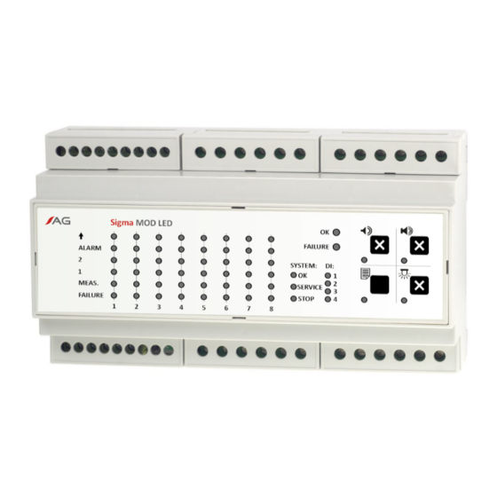
Sigma MOD LED – Front panel FAILURE FAILURE SYSTEM: MEAS. MEAS. SERVICE FAILURE FAILURE STOP STOP Figure 10: Sigma MOD LED front panel FAILURE FAILURE SYSTEM: SYSTEM: INPUTS: SERVICE SERVICE RELAY RELAY STOP STOP Figure 11: Sigma MOD DO front panel s. -
Page 17: Device Status Area
Sigma MOD DO front panel includes: 1. device status area, 2. status area for digital inputs DI, 3. status area for gas detectors (Sigma MOD LED) or relay outputs (Sigma MOD DO), 4. status area for the data transmission system (Sigma BUS), 5. keypad area. -
Page 18: Status Area For The Data Transmission System
3.1.5 Keypad Each button has an indicator to confirm is activation. The keypad can be used to read content of the device memory (only Sigma MOD LED) and to reset specific signals. 3.1.5.1 Specification of buttons for Sigma MOD LED... -
Page 19: Start-Up Of The Device, Test Of User Interface
Sigma MOD LED Right upon connection to a source of power voltage Sigma MOD LED controller starts a test of its user interface. The test consists in activation of all LED indicators on the front panel and horning the internal... -
Page 20: Basic View
www.atestgaz.pl 3.2.1.2 Sigma MOD DO For Sigma MOD DO controller all LED indicators on the front panel go on right after power up of the device. Basic view During regular operation the control unit modules display the following information: statuses of all lines (see Section 3.1.3), status of the control device (see Section 3.1.1), statuses of digital inputs DI (see Section 3.1.2), status of the system operation (see Section 3.1.4),... -
Page 21: Indication Of Detector Statuses - Special Statuses
www.atestgaz.pl Situation Description Indicators Buzzer Alarm The gas concentration exceeds the second warning threshold. Indicators 1, 2 and ALARM on the front panel are continuously ALARM on and the internal buzzer is activated (can be muted by means of the keypad) MEAS. -
Page 22: Response To Gas Concentration
www.atestgaz.pl Situation Description Indicators Buzzer Non-critical Detector malfunction that may negatively impact its failure measurement accuracy (e.g. exceeding of time until periodic ALARM calibration The detector still performs measurement. FAILURE indicator flashes evenly. (_∏_∏_∏_∏_). MEAS. FAILURE Critical failure The detector is damaged and does not perform measurement. FAILURE indicator is lit continuously, the remaining ones are ALARM turned of. -
Page 23: Figure 14: Indications Of Leds On The Front Panel Versus Gas Concentration Measured By The Detector
www.atestgaz.pl internal buzzer is activated, however it can be muted for a specific time by means of a keypad pushbutton (see Section 3.1.5). When gas concentration exceeds the maximum range permissible for the detector (overload threshold), the following actions take place: for detectors with catalytic sensors –... -
Page 24: Buzzer - Internal Acoustic Warning /Alarm Device
www.atestgaz.pl Buzzer – internal acoustic warning /alarm device The control module contains an internal audible warning/alarm device (buzzer) designed to horn an audible signal when intervention of the system operator is required, for instance when a gas hazard is detected or when any part /component of the system reports an error. -
Page 25: History Of Events
www.atestgaz.pl The buzzer can be also configured in such a way that is shall remain silent all the time. The desired configuration of the buzzer must be specified upon submission of the order (the buzzer is configured by the manufacturer at the factory workshop). History of events When the LED nearby the button ‘History of events’... -
Page 26: System Architectures
www.atestgaz.pl System architectures Ethernet, MODBUS TCP, Profibus Sigma EBUS Module of a signal converter MOD LCD PLC, SCADA Sigma MOD SEP 2 MOD LCD RS- 485, MODBUS ASCII / RTU 4×DI 8×PK SBUS Sigma Sigma Sigma Sigma MOD DRV MOD LED MOD LED MOD AO 4×DI... -
Page 27: Other Information
Local Authority, waste disposal companies and in the place of purchase. The equipment can also be returned to the manufacturer. Product marking Product code Device PW-033-A Control Unit Module Sigma MOD LED PW-033-C Control Unit Module Sigma MOD DO s. 27|31 User Manual: POD-002-ENG R03... -
Page 28: Technical Specification
Modbus ASCII, 19200 b/s 7E1 optionally: Modbus RTU, 19200 b/s 8N1 Integrated signalling equipment (optical) LED controls Integrated signalling equipment (acoustic) 70dB, 0.1 m distance (only for Sigma MOD LED) Protection class Dimension See section 5.6 Acceptable cables 1 – 2 mm... -
Page 29: Dimension
www.atestgaz.pl Dimension Dimension in mm. Figure 18: Dimension of device s. 29|31 User Manual: POD-002-ENG R03... -
Page 30: Configuration
www.atestgaz.pl Configuration Serial no.: Product revision: Gas detector addresses: SBUS port ExBUS port Protocols and parameters: address: address: ASCII, 19200 7E1 ......... Output Default setting Configuration on customer's request (according to the manual) WARNING 1 WARNING 2 ALARM VISUAL ALARM (locked) SOUND ALARM MEASUREMENT SERVICE... -
Page 31: Appendices
Appendices DEZG017-ENG – EU Declaration of Conformity – Sigma MOD LED, LCD, DO PU-Z-003-ENG – Guidelines to the cabling of the system with an RS-485 interface PU-Z-005-ENG – Sigma Gas system – wiring diagram PU-Z-006-ENG – The memory map for the GTW functionality in Control Unit Modules Sigma MOD LCD, Sigma MOD LED, Sigma MOD DO s. - Page 32 EU Declaration of Conformity Atest Gaz A. M. Pachole sp. j. declares with full responsibility, that the product: (Product description) (Trade name) (Type identifier or Product code) Control Unit Module Sigma MOD LED PW-033 Sigma MOD LCD Sigma MOD DO complies with the following Directives and Standards: in relation to Directive 2014/30/EU –...
- Page 33 www.atestgaz.pl Guidelines to the cabling of the system with an RS-485 interface Introductory It is recommended that all system components are made according to the design created by person with the necessary skills and competence. Connection cable The data transmission line for the gas detectors working in the RS-485 standard should be performed only with the use of a shielded twisted pair cable.
- Page 34 www.atestgaz.pl Power supply of the gas detector As a standard, in gas detectors with digital data transmission, it is assumed that the voltage cannot drop below 12 V (see the documentation of the detector). The power consumption of the detector is constant within the range of acceptable voltages.
- Page 35 www.atestgaz.pl Sigma Gas system – wiring diagram Atest-Gaz A. M. Pachole sp. j. tel.: +48 32 238 87 94 p. 1/1 Appendix: PU-Z-005-ENG R01 ul. Spokojna 3, 44-109 Gliwice, Poland fax: +48 32 234 92 71 VAT No.: PL 9691433231 e-mail: contact@atestgaz.pl •...
- Page 36 www.atestgaz.pl The memory map for the GTW functionality in Control Unit Modules Sigma MOD LCD, Sigma MOD LED, Sigma MOD DO Memory map Registers range Description 40001 – 40064 Status of detectors at channels 1 – 32 40065 – 40066 Status of R1 ÷...
- Page 37 www.atestgaz.pl Flag Description Test Test mode Warm_Up Sensor's warm up Sensor_Inhibit Inhibit mode Comm_Error Error of communication with a detector Calibration_Warning Calibration time exceeded (non-critical error) Monitoring Measurement in progress System_Stop The system is stopped N – gas concentration. The value of 0 corresponds to zero concentration whilst the value of 1000 corresponds to the concentration equal to the measurement range of the detector.
- Page 38 www.atestgaz.pl Temperature in measuring head of detectors (read-only) Channel no. Register Name Description Type 40068 Temp. Temperature in measuring head 40069 Temp. Temperature in measuring head 40099 Temp. Temperature in measuring head External DI control inputs (read / write) Register Name Description Type / range...
- Page 39 www.atestgaz.pl Interface for execution of operator commands (read /write; available only for Sigma MOD LCD) Register Name Description Type /range 43501 Command_Status Current status of the command execution Write – data byte is ignored Read – status, the available values are: •...
- Page 40 www.atestgaz.pl Notes...
- Page 41 www.atestgaz.pl Notes...
- Page 42 www.atestgaz.pl Notes...
- Page 44 Atest Gaz A. M. Pachole sp. j. Spokojna 3, 44-109 Gliwice tel.: +48 32 238 87 94 fax: +48 32 234 92 71 e-mail: contact@atestgaz.pl For more details on our devices and other products and services offered by us, visit:...
Need help?
Do you have a question about the Sigma MOD LED and is the answer not in the manual?
Questions and answers