Table of Contents
Advertisement
Quick Links
Advertisement
Chapters
Table of Contents

Related Manuals for Atest Gaz Sigma Control L


Summary of Contents for Atest Gaz Sigma Control L
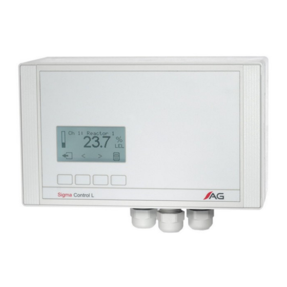
- Page 1 User's Manual Control Unit Sigma Control L Product code: PW-072-A POD-026-ENG R11...
- Page 2 Systems for Gas Detection, that in the best possible way will find out and alert about any potential gas threat or lack thereof We invite you to familiarize yourself with our offer on www.atestgaz.pl Atest Gaz A. M. Pachole sp. j. ul. Spokojna 3, 44-109 Gliwice Poland tel.: +48 32 238 87 94...
- Page 3 www.atestgaz.pl Remarks and reserva!ons Connec on and opera on of the device is allowed only a er reading and understanding the contents of this document. Keep User's Manual with the device for future use. The manufacturer bears no responsibility for errors, damages and failures caused by improper selec on of devices and cables, improper installa on or failure to understand the contents of this document.
-
Page 4: Table Of Contents
www.atestgaz.pl Table of contents 1 Preliminary informa!on........................6 1.1 Safety................................6 1.2 Purpose..............................6 1.3 Device characteris cs..........................6 2 Opera!on descrip!on.........................7 3 Design descrip!on..........................8 4 Input-output interfaces........................9 4.1 Relay output fault...........................10 4.2 All-purpose relay outputs (PK1 – PK3)....................11 4.3 Digital Inputs DI............................12 4.4 Visual and acous c indicator outputs....................12 4.5 Service interface.............................14 4.6 Extension Module Interface........................14 5 User's interface..........................15... - Page 5 Figure 8: Valve control and the opera!on principle for an acous!c indicator output........13 Figure 9: Installing the Extension Module....................14 Figure 10: Sigma Control L Unit front panel with fields descrip!on............15 Figure 11: Push bu:on and its func!on....................16 Figure 12: Interface structure........................17 Figure 13: Welcome screen........................18...
-
Page 6: Preliminary Informa!On
Purpose Sigma Control L is an advanced Control Unit for use with small size gas detec on systems. It controls all the devices connected and integrates them to create a single Sigma Gas system. Its advantage is to provide two... -
Page 7: Opera!On Descrip!On
Sigma Control L Unit is designed for indoor use. It cannot be installed in explosion (Ex) zones. Opera!on descrip!on Sigma Control L Unit reads the status of detectors connected to the system. This informa on is presented on the display and the built-in Visual System Indicator. Based on gas concentra on measured and other special statuses (e.g. -
Page 8: Design Descrip!On
www.atestgaz.pl Design descrip!on The device design is presented in Figure 1 and 2. Before you remove the front panel, disconnect the device from its power source. p. 8|37 User's Manual: POD-026-ENG R11... -
Page 9: Input-Output Interfaces
www.atestgaz.pl Input-output interfaces The interfaces are available on a terminal strip accessible afar front panel removal and on its bo+om wall. The descrip on of terminal strip is presented in figure 3 and table 1. For Extension Module interface descrip on – see sec on 4.6, or service interface – see sec on 4.5. Figure 3: Terminal strip Port symbol Terminal... -
Page 10: Relay Output Fault
Default configura on for Sigma Control L Unit is presented below (see table 2). I/O configura!on / Parameters Func!on / Parameter No. of detectors Relay outputs Warning 1 (no delay on/off, normally open NO) Warning 2 (no delay on/off, normally open NO) Alarm (no delay on/off, normally open NO) -
Page 11: All-Purpose Relay Outputs (Pk1 - Pk3)
www.atestgaz.pl All-purpose relay outputs (PK1 – PK3) Control Unit is fi+ed with three all-purpose relay outputs. The outputs can operate in one of the two statuses: as enabled or disabled. The terminals are then connected as shown in the diagram below. Control Unit Relay outputs Enabled... -
Page 12: Digital Inputs Di
www.atestgaz.pl Program Descrip!on Addi!onal parameters SO copy The output copies the status of visual indicator output. SA copy The output copies the status of acous c indicator output. Valve control When at any detector, alarm threshold is detected, the Enable delay. Disable delay. -
Page 13: Figure 7: Opera!On Principle For Visual Indicator Output With Sustained
www.atestgaz.pl Gas concentra on Warning 1 threshold Pushbu+on SO output Time Warning - output disable The output cannot be turned Warning disappears - Operator presses the off – warning 1 is ac ve (the despite this the pushbu+on – output pushbu+on does not output is s ll enabled disables... -
Page 14: Service Interface
At the bo+om housing wall (see Figures 1 and 2) there is a service connector. It is designed to connect a service tool to Sigma Control L Unit (e.g. a PC with proper so ware installed). Interface parameters – see sec on 10. -
Page 15: User's Interface
Front panel Sigma Control L Unit front panel includes: system status LED field (see sec on 5.1.2), visual indicator System field (see sec on 5.1.1), LCD display field (see sec on 5.1.3),... -
Page 16: Table 4: Descrip!On Of System Visual Indicator Led's
www.atestgaz.pl 5.1.1 System Visual Indicator Field System Visual Indicator allows the operator, who is normally focused on other ac vi es, to quickly assess site gas safety status – by taking a quick glance at the indicator and confirming that only the green LED is on. System Visual Indicator is responsible for displaying four independent informa on: Color Descrip!on... -
Page 17: Interface Structure
www.atestgaz.pl Interface structure Detailed view Interface test / Detector Menu System view Welcome screen Detector 1 [0] History [0] Detector Info TEST [0] Concentra on diagram [1] Cancel lock [2] Zero the detector [2] Noise gateway Detector n [2] Alarm threshold [1] "Inhibit"... -
Page 18: Star Ng The Unit, Tes Ng The User's Interface
Star!ng the unit, tes!ng the user’s interface To check the Sigma Control L Unit for proper opera on, perform the user’s interface test. While tes ng, the unit starts all front panel LEDs (status and System Visual Indicator LEDs) as well as internal buzzer, all display pixels become darkened. -
Page 19: Table 6: Collec!Ve Text System Descrip!On
www.atestgaz.pl Beacon status System status Detector status Pushbu+on func ons Figure 14: System view screen – system with up to 10 detectors Beacon status System status Detector status Pushbu+on func ons Figure 15: System view screen – system with 10 to 20 detectors System status: Informa on about system status is displayed interchangeably with informa on about date and me (or clock not being set) –... -
Page 20: Table 7: Indicator Ac!Va!On Status
www.atestgaz.pl Beacon status: This sec on presents indicator ac va ons: Icon Descrip!on Ac ve visual indicator. When the indicator is disabled, this field is empty. Ac ve acous c indicator. When the indicator is disabled, this field is empty. Table 7: Indicator ac!va!on status Detector status: This sec on presents the status of individual detectors. -
Page 21: Table 8: Detector Statuses
www.atestgaz.pl Detector statuses can be as follows: Icon Descrip!on The detector operates in monitoring mode – it takes measurement and its indica ons are reliable. The detector operates in special mode. Its indica ons are taken into account in the Control Unit output control. -
Page 22: Detailed Detector View
www.atestgaz.pl Detailed detector view The screen is divided into a few sec ons (see figure 18). Detector indica on Loca on Detector No. Detector panel Pushbu+on Detector func ons status Figure 18: Screen showing detailed detector view Detector panel – see sec on 5.5. Detector No. -
Page 23: Control Unit Detailed View
The unit is opera onal. AW <fault code > Sigma Control L Unit is faulty. Fault code is a hexadecimal number. Text message explaining fault code find in unit's menu – see sec on 5.9. Table 11: Control Unit status text descrip!on Detector menu Informa on on access to op ons –... -
Page 24: Table 12: Detector Menu
www.atestgaz.pl Op!on Descrip!on 1. History This op on allows the user to browse recorded statuses (threshold exceeding, faults) that occurred at individual detectors. Status memory can be cleared. 2. Detector info It displays detailed detector informa on, including: • Range, alarm threshold values. •... -
Page 25: Control Unit Menu
www.atestgaz.pl Control Unit menu Informa on on access to op ons – sec ons 5.2 and 5.3. Op!on Descrip!on 1. Events history This func on allows to view logged system states. 2. Unit info Presents detailed informa on on Control Unit, including: •... -
Page 26: Events History
Buzzer – internal acous!c indicator Sigma Control L Unit module has a built-in internal acous c indicator, called a buzzer. It is designed to generate an acous c signal when operator interven on can be necessary, including a gas risk or system component fault. -
Page 27: Figure 21: Internal Buzzer Opera!On - !Me Diagram
www.atestgaz.pl The buzzer is triggered when: gas alarms, i.e. when warning level 1 or 2 and alarm are reported by any of the detectors connected, fault, i.e. a cri cal fault of any detectors connected appears, loss of communica on and in the case of Control Unit Module cri cal fault. -
Page 28: Op!Ons For Scl Connec!On In A Gas Detec!On System
The buzzer can be configured so as not to be triggered at all. Op!ons for SCL connec!on in a gas detec!on system Below we present some examples for connec ng Sigma Control L Unit connec ons with other gas detec on system components. -
Page 29: Figure 24: A Connec!On Example: Bi-Colour 24 V Dc Indicator To Relay's Outputs
www.atestgaz.pl p. 29|37 User's Manual: POD-026-ENG R11... -
Page 30: Figure 26: A Connec!On Example: Power Supply 24 V Dc And 24 V Dc Indicators
www.atestgaz.pl Figure 27: A connec!on example: power supply 230 V AC, 230 V AC indicators p. 30|37 User's Manual: POD-026-ENG R11... -
Page 31: Selec!Ng Coopera!On Devices
Figure 28: A connec!on example: bi-colour 230 V AC indicator to relays outputs Selec!ng coopera!on devices When Sigma Control L is supplied by 230 V AC, the total current consumed by devices connected to the Control Unit (through detector bus and indicator terminals) cannot exceed 1.5 A, while the current consumed at indicator terminals cannot exceed 1.15 A. -
Page 32: Table 14: Current Consump!On By Connected Detectors
www.atestgaz.pl Product code Current consumed [mA] FLED FLED.A FLED FLED.A PW-044 PW-017 FLED FLED.A FLED FLED.A PW-093 FLED Table 14: Current consump!on by connected detectors Informa on on the types of cables required and the method for preparing the gas detec on system connec ons –... -
Page 33: Life Cycle
www.atestgaz.pl Example 2: Power supply 230 V AC 10 x detector PW-044-SM-ELm-0-ALB-0, current input 10 x 70 mA = 700 mA 2 x visual-acous c indicator, current input 2 x 480 mA = 960 mA Current input for indicators: 960 mA < 1150 mA Correctly Total current input: 1660 mA >... -
Page 34: Start Up
www.atestgaz.pl Unused screw terminals must be ghtened. Correct cable rou ng Incorrect cable rou ng Figure 29: Example connec!on of cables to the device Start up Once the unit is installed change access passwords (see sec on 5.9). Perform a load test before opera ng your gas detec on system for the first me and a er each system component replacement –... -
Page 35: Periodical Opera Ons
www.atestgaz.pl Periodical opera!ons It is recommended to perform interface test (see sec on 5.4) once a week. It is recommended to perform output test (see sec on 5.9) once a month. 8.5.1 Replacement of consumables The life cycle of consumables/ wearing components is presented in table 16. To replace a discharged ba+ery or a burned fuse, take the following steps: 1. -
Page 36: Technical Specifica!Ons
EN 60947 – Low-voltage switchgear and control gear. If to “24 VDC” input a voltage of approx. 21 – 29 V is connected, then the output voltage is the same as the Sigma Control L Unit power supply voltage. p. 36|37... -
Page 37: List Of Consumables
Table 17: Method of product's marking Appendices DEZG086-ENG – EU Declara on of Conformity – Sigma Control L PU-Z-062-ENG – Extension Module PCA-062A-E2 Port GTW (RS -485, isolated) PU-Z-003-ENG – Guidelines to the cabling of the system with an RS-485 interface When power supply is disconnected. - Page 38 www.atestgaz.pl EU Declaration of Conformity Atest-Gaz A. M. Pachole sp. j. declares with full responsibility, that the product: (Product description) (Trade name) (Type identifier or Product code) Control Unit Sigma Control L PW-072 complies with the following Directives and Standards: in relation to Directive 2014/30/EU –...
- Page 39 5.1 Transportation............................3 5.2 Module assembly – installation......................3 5.3 Module configuration.........................3 6 Memory maps............................4 6.1 Memory map for Sigma Control L Unit....................4 7 Utilization..............................7 8 Technical specifications..........................8 General information Extension Module PCA-062A-E2 extends the functionalities of units where it is installed, by an additional, dual, digital port RS-485.
-
Page 40: Design Description
Internal communication interface terminal strip connector Galvanic isolator Figure 2: Device schematic diagram Atest Gaz A. M. Pachole sp. j. tel.: +48 32 238 87 94 Appendix: PU-Z-062-ENG R04 ul. Spokojna 3, 44-109 Gliwice, Poland fax: +48 32 234 92 71 s. -
Page 41: User's Interface
JP1 jumper setting Operation Schematic diagram Terminator off Terminator on 120Ω Atest Gaz A. M. Pachole sp. j. tel.: +48 32 238 87 94 Appendix: PU-Z-062-ENG R04 ul. Spokojna 3, 44-109 Gliwice, Poland fax: +48 32 234 92 71 s. 3|8 VAT No.: PL 9691433231... -
Page 42: Memory Maps
(E), odd (O), no (N) number of character bits: 7 (only for Modbus ASCII) or 8 Memory maps Memory map for Sigma Control L Unit Register range Description 40001 – 40040 Detector status at channels 1 – 20 40041 –... - Page 43 Collective system failure CU_fail Control Unit module failure 2..15 Unused – always zero Atest Gaz A. M. Pachole sp. j. tel.: +48 32 238 87 94 Appendix: PU-Z-062-ENG R04 ul. Spokojna 3, 44-109 Gliwice, Poland fax: +48 32 234 92 71 s.
- Page 44 PK activation failure 9..15 External_DI_9..15 Input no. 9..15 Unassigned S16 – 16-bit unsigned. Atest Gaz A. M. Pachole sp. j. tel.: +48 32 238 87 94 Appendix: PU-Z-062-ENG R04 ul. Spokojna 3, 44-109 Gliwice, Poland fax: +48 32 234 92 71 s.
-
Page 45: Utilization
The product can be also returned to its manufacturer. Atest Gaz A. M. Pachole sp. j. tel.: +48 32 238 87 94 Appendix: PU-Z-062-ENG R04 ul. -
Page 46: Technical Specifications
Terminal cable cross-section 0,15 - 1,5 mm – solid wire 0,15 - 1 mm – multi - wire Atest Gaz A. M. Pachole sp. j. tel.: +48 32 238 87 94 Appendix: PU-Z-062-ENG R04 ul. Spokojna 3, 44-109 Gliwice, Poland fax: +48 32 234 92 71 s. -
Page 47: Connection Cable
www.atestgaz.pl Guidelines to the cabling of the system with an RS-485 interface Introductory It is recommended that all system components are made according to the design created by person with the necessary skills and competence. Connection cable The data transmission line for the gas detectors working in the RS-485 standard should be performed only with the use of a shielded twisted pair cable. - Page 48 www.atestgaz.pl Power supply of the gas detector As a standard, in gas detectors with digital data transmission, it is assumed that the voltage cannot drop below 12 V (see the documentation of the detector). The power consumption of the detector is constant within the range of acceptable voltages.
Need help?
Do you have a question about the Sigma Control L and is the answer not in the manual?
Questions and answers