Sign In
Upload
Manuals
Brands
Atest Gaz Manuals
Control Unit
Sigma MOD LED
Atest Gaz Sigma MOD LED Manuals
Manuals and User Guides for Atest Gaz Sigma MOD LED. We have
2
Atest Gaz Sigma MOD LED manuals available for free PDF download: User Manual
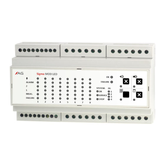
Atest Gaz Sigma MOD LED User Manual (52 pages)
Control Unit Module
Brand:
Atest Gaz
| Category:
Control Unit
| Size: 2 MB
Table of Contents
Table 1: Optical Indicators Status Notation
3
Table of Contents
4
Preliminary Information
6
General Description
6
Figure 1: Application of the Control Unit Module Sigma MOD LCD
7
Figure 2: Example of Collaboration between the Sigma MOD LCD Device and Ambient Environment
7
Operation Principle
8
Device Characteristics
8
Input-Output Interfaces
9
Relays Output R1 - R8
9
Figure 3: Electric Connections
9
Figure 4: Galvanic Separation between Various Interfaces of the Control Unit Module - Structural Diagram
9
Table 2: Electric Interface Description
10
Figure 5: Relays in Active and Inactive State
10
Binary Inputs DI 1 - DI 4
12
Table 3: Default Configuration of Relay Outputs
12
Figure 6: Visual Alarm (Locked) - Behaviour of the R4 Output Depends on the Gas Concentration
12
Figure 7: Sound Alarm - Behaviour of the R5 Output Depends on the Gas Concentration
12
SBUS Communication Port
13
Table 4: Default Assignment of Digital Inputs (DI)
13
Figure 8: Delivery of Input Signals to Logic Inputs DI 1 and DI 2
13
Exbus Communication Port - Data Gateway, External Data Inputs
14
Table 5: Default Configuration of External DI Input
14
Polarity of Communication Lines
15
User Interface
15
Front Panel
15
Table 6: Configuration of Polarity for SBUS and Exbus Ports
15
Figure 9: Jumpers to Set Polarity of SBUS and Exbus Ports, Available after Removing of the Protection Lid
15
Figure 10: Sigma MOD LCD Front Panel
15
Device Status Area
16
Status Area of Digital Inputs (DI)
16
Status Area for System Operation
16
Table 7: Operation of Leds for Indication of the Device Status
16
Table 8: Operation of Leds for Status Indication of Digital Inputs (DI)
16
Table 9: Operation of Leds for Indication of the Detector Status
16
LCD Display
17
Keypad
17
Map of the Controller Interface
17
Table 10: Designation of Keypad Buttons
17
Table 11: Available Combinations of Buttons
17
Figure 11: Map of the Control Unit Interface
18
Control Unit Start Up, Interface Self-Test
19
Home Screen
20
Table 12: Specification of the Display Content for the Home Screen
20
Figure 12: Specific Fields of the Home Screen
20
General Code of Indications
21
Detector's State Signalling - Gas Alarms
21
Indication of Detector Statuses - Special Statuses
22
Table 13: Indication of the Detector Statuses - Gas Warning and Alarms
22
Response to Gas Concentration
24
Table 14: Indication of the Detector Statuses - Special Statuses
24
Buzzer - Internal Acoustic Warning /Alarm Device
25
Figure 13: Indications of Leds on the Front Panel Versus Gas Concentration Measured by the Detector
25
Access Rights to the Menu Options - Login/Logout Procedures
26
Figure 14: Behaviour of the Internal Buzzer - Signal Waveforms
26
Detector Menu
27
Figure 15: Layout of Fields in the Detector Menu
27
History
28
Table 15: Assignment of Menu Fields on the LCD Display
28
Figure 16: Interface Leds with Information about Historical Events
28
Detector Info
29
Reset a Locked Detector
29
Tuning of the Detector Zero Level
30
Noise Gate
30
Warning /Alarm Thresholds
30
Inhibit" Mode
31
Logout
32
Device Menu
32
Device Info
32
Language
32
Password Change for Level 1
32
Password Change for Level 2
33
Settings for the Internal Buzzer
33
Gateway Settings
34
Logout
34
Results of Operations
34
System Architectures
35
Table 16: Codes of Communication Errors
35
Figure 17: Example of System Architecture
35
Other Information
36
Mechanical Mounting of the Control Unit
36
Commissioning of the Unit
36
Utilization
36
Product Marking
36
Technical Specification
37
Table 17: Technical Specification
37
Dimension
38
Figure 18: Dimension of Device
38
Configuration
39
Appendices
40
Advertisement
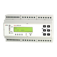
Atest Gaz Sigma MOD LED User Manual (44 pages)
Control Unit Module
Brand:
Atest Gaz
| Category:
Control Unit
| Size: 1 MB
Table of Contents
Table 1: Optical Indicators Status Notation
3
Table of Contents
4
Preliminary Information
6
General Description
6
Figure 1: Application of the Control Unit Module Sigma MOD LED
7
Figure 2: Example of Collaboration between the Sigma MOD LED Device and Ambient Environment
7
Operation Principle
7
Device Characteristics
8
Figure 4: Galvanic Separation between Interfaces of the Control Unit Module - Structural Diagram
9
Figure 3: Electric Connections
9
Input-Output Interfaces
9
Terminal Blocks
9
Relays Output R1 - R8
9
Table 2: Description of the Electric Interface
10
Figure 5: Relays in Active and Inactive State
10
Table 3: Default Configuration of Relay Outputs Sigma MOD LED
12
Table 4: Default Configuration of Relay Outputs Sigma MOD DO
12
Figure 6: Visual Alarm (Locked) - Behaviour of the R4 Output Depends on the Gas Concentration
13
Figure 7: Sound Alarm - Behaviour of the R5 Output Depends on the Gas Concentration
13
Binary Inputs DI 1 - DI 4
13
SBUS Communication Port
14
Exbus Communication Port - Data Gateway, External Data Inputs
14
Figure 8: Delivery of Input Signals to Logic Inputs DI 1 and DI 2
14
Table 5: Default Assignment of Digital Inputs (DI)
14
Figure 9: Jumpers to Set Polarity of SBUS and Exbus Ports, Available after Removing of the Protection Lid
15
Polarity of Communication Lines
15
Table 6: Default Configuration of External DI Input
15
Figure 10: Sigma MOD LED Front Panel
16
Figure 11: Sigma MOD DO Front Panel
16
Sigma MOD LED - Front Panel
16
Table 7: Configuration of Polarity for SBUS and Exbus Ports
16
User Interface
16
Device Status Area
17
Table 10: Operation of Leds for Indication of the Detector Status
17
Table 9: Operation of Leds for Status Indication of Digital Inputs (DI)
17
Keypad
18
Status Area for the Data Transmission System
18
Table 11: Operation of Leds for Indication of the Detector Status
18
Table 12: Operation of Leds for Status Indication of the Data Transmission System
18
Table 13: Description of Buttons for Sigma MOD LED
18
Table 14: Available Combinations of Buttons
18
Figure 12: Front Panel - Test of User Interface
19
Figure 13: Front Panel - Number of the Product Revision
19
Start-Up of the Device, Test of User Interface
19
Table 15: Description of Keypad Buttons for Sigma MOD DO
19
Basic View
20
Table 8: Operation of Leds for Indication of the Device Status
17
Status Area of Digital Inputs (DI)
17
Status Area for System Operation
17
General Code of Indications
20
Detector's State Signalling - Gas Alarms
20
Table 16: Indication of the Detector Statuses - Gas Warning and Alarms
21
Indication of Detector Statuses - Special Statuses
21
Table 17: Indication of the Detector Statuses - Special Statuses
22
Response to Gas Concentration
22
Figure 14: Indications of Leds on the Front Panel Versus Gas Concentration Measured by the Detector
23
Figure 15: Behaviour of the Internal Buzzer - Signal Waveforms
24
Buzzer - Internal Acoustic Warning /Alarm Device
24
Figure 16: Interface Leds with Information about Historical Events
25
Table 18: Indications of Leds for the System Status
25
History of Events
25
Figure 17: Example of System Architecture
26
System Architectures
26
Commissioning of the Unit
27
Utilization
27
Product Marking
27
Other Information
27
Mechanical Mounting of Detectors
27
Technical Specification
28
Table 19: Technical Specification
28
Dimension
29
Figure 18: Dimension of Device
29
Configuration
30
Appendices
31
Advertisement
Related Products
Atest Gaz Sigma Control L
Atest Gaz Sigma MOD DRV
Atest Gaz Sigma MOD AO
Atest Gaz Sigma MOD DO
Atest Gaz Sigma SmArt
Atest Gaz Alpa MOD LED1
Atest Gaz Alpa MOD LED8
Atest Gaz EcoAlpa PW-054 Series
Atest Gaz EcoAlpa PW-054-LED2-1212
Atest Gaz EcoAlpa PW-054-LED2-230
Atest Gaz Categories
Control Unit
Gas Detectors
Security Sensors
Controller
More Atest Gaz Manuals
Login
Sign In
OR
Sign in with Facebook
Sign in with Google
Upload manual
Upload from disk
Upload from URL