Advertisement
Quick Links
OPERATION OF FEATURES
1. LED Enable / Disable (Switch A)
ON = LED Enable
OFF = LED Disable
2. Self Test (Switch B)
ON = Periodic self test mode
OFF = Remote self test mode
2.1 Periodic Test
In periodic test mode, a self test is commenced after 5 hours of PIR
inactivity. If the test passes there is a short delay before the detector
settles and resumes to normal operation.
2.2 Remote Test
The remote test will only be activated if the RT terminal is connected to
the control panel. If the RT connection goes high then the detector
immediately performs a self test. If the test passes then the detector
immediately performs a self test, if the test passes then the relay changes
state for 3 seconds.
2.3 Failure of a test (See diagram
H5
)
If the test fails the LEDs flash alternately (See diagram
H5
)
If a valid alarm activation is processed then the detector will return to its
normal operation. In the unlikely event of a continuous test failure then
please contact Pyronix technical support.
3. Relay modes (Switch C)
ON = Relay is in normally closed mode. (N/C)
OFF = Relay is in normally open mode. (N/O)
4. Digital signal processing settings (Switch D & E)
PC 1
= One detection zone must be crossed.
SPP+
= Two opposing detection zones must be crossed.
PC 2
= Two detection zones must be crossed.
SPP+1 = Two opposing detection zones and any other zone must be
crossed.
5. Walk test LED enable (Switch F)
ON = Walk test LEDs are disabled.
OFF = Walk test LEDs are enabled.
5.1 When the walk test LEDs are enabled three LEDs will illuminate in a
normal alarm activation. See diagram
H3
5.2 When the walk test LEDs are disabled the middle LED will illuminate
in a normal alarm activation. See diagram
H2
5.3 The walk test LEDs will be automatically disabled after 10 minutes to
reduce power consumption.
6. C+ Latch terminal
This function allows an activated PIR to be identified after an alarm
condition by a flashing LED, see diagram
H4
6.1 Connection
Connect (C+) to a PGM at the control panel programmed to be 12V after
arming. To reset the latch memory, create a 5 second switch from OV to
12V and back to 0V.
6.2 Pyronix Panels
Connect detector input C+ to a PGM output configured as C+ using a
2K2 resistor from AUX+ to the PGM output.
To reset the latch memory enter the user code twice within 5 seconds.
7. RT Remote self test terminal
If remote self test is selected (switch B off), a self test can be initiated by a
momentary switched 0 volt input. Refer to section 8.1 and 8.2
8. E- Remote LED enable terminal
To use the remote LED enable feature switch A must be in the OFF
position.
8.1 Connections
To remotely enable LEDs, 0 volts must be applied to the E- terminal.
8.2 Pyronix Panels
Connect detector input E- to a PGM output and configure as walk test.
DIP switches (see diagram
)
C
Note: As Factory Default all switches are ON
SWITCH
FEATURE
POSITION
ON
A
LED Enable
OFF
ON Periodic self test
B
Self Test mode
OFF Remote self test
C
Relay mode
ON
Relay normally closed
OFF
Relay normally open
D
Digital signal
ON
Processing
OFF
OFF
ON
E
Digital signal
ON
Processing
ON
OFF
OFF
F
Walk test mode
ON
Walk test LEDs disable
OFF
Walk test LEDs enable
H1
H2
H3
Power up
Normal alarm
Normal alarm
walk test selected
H4 Latch
Center LED flashes at intervals of 1-2 seconds
H5 Fail self test
Center and outside LEDs flash alternately
OPTIONAL TAMPER UNIT
Note: The Kudos detector may be fitted with an optional back tamper, which is sold separately.
1
2
1
1A
1A
1B
1C
2
1B
C
3
1C
3A
3B
4
5
6
6
5
7
WARRANTY
This product is sold subject to our standard warranty conditions and is warranted against
defects in workmanship for a period of five years. In the interest of continuing improvement
of quality, customer care and design, Pyronix Ltd reserve the right to amend specifications
without giving prior notice
INSTALLATION
GB
1. Remove case lid by unscrewing fixings screw as illustrated in
and unclip the PCB, taking care not to touch the Pyro sensor
labeled
.
C1
MEANING
2. Choose wall fixing holes, labeled
D2
and
LED Enable
3. Mark wall for fixing positions (Do not route wires near mains cabling,
avoid vibrating surfaces and mount only on a solid wall).
LED Disable
4. Drill fixing holes.
5. Fix case to wall.
6. Replace PCB again taking care not to touch the pyro sensor (labeled
C1
on diagram).
7. Select and fit the appropriate lens for your application (See diagram
8. Using dip switches (See diagram
C2
) select required features and modes of
operation.
SPP+
9. Carry out walk test.
SPP+1
10. Re fit detector front cover using fixing provided (See diagram
PC 1
POTENTIAL FALSE ALARM HAZARDS.
PC 2
1. Direct sunlight on detector may cause false alarms.
2. Pets and animals may cause false alarms.
SPP+
SPP+1
3. Mounting detector near heaters may cause false alarms.
PC 1
4. Draughts from open windows may cause false alarms.
PC 2
DIAGRAMS
A
Coverage Patterns
B
Dimensions and weight
C
Board layout
C1
Pyro sensor
C2
DIP Switches
C3
Optional rear tamper.
Mounting and cable entry knockouts
D
D1
Cable entry knockouts
Wall fixing knockouts
D2
D3
Wall fixing knockouts
Detection methods
E
Detailed connections
F
F1
Control panel connections
Tamper operation
F2
Alarm relay operation (N/C)
F3
F4
Alarm relay operation (N/O)
Removal and replacement of front cover and lenses
G
Front cover fixing screw
G1
G2
Removing and replacing the lens
SPECIFICATIONS (QUICK REFERENCE)
3
3A
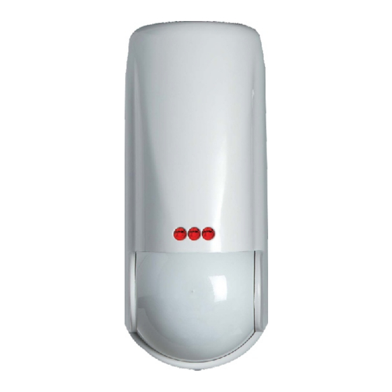
Model:
Kudos
Casing:
White3mm ABS Back / Front cover
3B
White 3mm HDPE lens cover, 0.7mm in faceted area
Lens:
Volumetric: 20m, 74 zones, 7 planes, 2.4m mounting height
Curtain: 25m, 24 zones, 6 planes, 2.4m & 5m mounting height
Long range: 45m, 46 zones, 6 planes 2.4m mounting height
.
4
Detection method:
Low noise dual element pyroelectric sensor
Digital signal processing:SPP+ , SPP+1, PC 1, PC 2.
Detection speed:
0.3 - 3.0 m/s
Operating Voltage:
9-16 VDC
Current consumption:
22mA Quiescent
@13.8V
48mA Walk test mode
7
105mA self test (short burst per test)
Relay Output:
60Vdc, 50mA (42.4Vac peak)
Mounting Height:
1.8 - 2.4m
Tamper Switch:
Normally closed voltage free contacts
(12V 50mA max rating)
0
0
0
Storage Temp:
-40 C / 80 C (-40 F / 176 F )
0
0
0
Operating Temp:
-30 C / 70 C (22 F / 158 F )
Emissions:
EN55022 Class B
Immunity:
To new European Standard EN50130-4
Accessories:
Optional back tamper
G1
D3
on diagram.
G2
).
).
G1
Technical help line (UK only): 0870 122 3360
customer.support@pyronix.com
PYRONIX LTD
0C03
This product is approved for use in the
Residential, Commercial and Light Industrial Environment.
0
This product complies with TS50131-2-2. at security grade 2,
0
UK = Suitable for use with systems installed to PD6662:2004 (AMD)
EXPORT = Suitable for use with systems installed to EN50131-1
Kudos
Pyronix Limited
Pyronix House
Braithwell Way
Hellaby, Rotherham
S66 8QY, ENGLAND
This is a national rate line
www.pyronix.com
R
TS50131-2-2
EN50131-1
2
PD6662:2004
Security Grade 2
Environmental Class 2
environmental class 2.
RINS 411-7
Advertisement

Related Manuals for Pyronix Kudos


Summary of Contents for Pyronix Kudos
- Page 1 6. C+ Latch terminal S66 8QY, ENGLAND Note: The Kudos detector may be fitted with an optional back tamper, which is sold separately. This function allows an activated PIR to be identified after an alarm Technical help line (UK only): 0870 122 3360...
- Page 2 COVERAGE PATTERN AND PLAN VIEW DIMENSIONS AND WEIGHT BOARD LAYOUT 20m VOLUMETRIC LENS ON = Normal, link fitted 25m CURTAIN LENS C+ RT E- 24 zone edges 74 zone edges OFF = Optional, rear tamper 6 planes 7 planes spring fitted HORIZONTAL COVERAGE HORIZONTAL COVERAGE AT MINIMUM RANGE Optional...
Need help?
Do you have a question about the Kudos and is the answer not in the manual?
Questions and answers