
Subscribe to Our Youtube Channel
Related Manuals for Black Box PSE544-DE-R2


Summary of Contents for Black Box PSE544-DE-R2
- Page 1 USER MANUAL PSE544-DE-R2, PSE544-FR-R2 POWER SWITCH OVER IP OFFICE- CABINET 24/7 TECHNICAL SUPPORT AT 1.877.877.2269 OR VISIT BLACKBOX.COM...
- Page 2 EN55022 Class B:2010, EN55024:2010, EN50581:2012 PSE544-DE-R2 and PSE544-FR-R2 PSE544-DE-R2 (with German/Schuko Sockets) and PSE544-FR-R2 (with French/UTE Sockets) are extension leads that allows you to switch ON or OFF the power supply of any electric device over an Ethernet 10Base-T or 100Base-T network.
-
Page 3: Table Of Contents
NEED HELP? LEAVE THE TECH TO US LIVE 24/7 TECHNICAL CONTENTS SUPPORT 1.877.877.2269 1.1 DESCRIPTION ............................................6 1.1.1 Front Panel of PSE544 .............................................6 1.1.2 Package list ..................................................7 2.1 INSTALLATION / CABLING .......................................8 3.1 PSE544 NETWORK SETTINGS .......................................9 3.1.1 IP Configuration through the LAN using the BB-Finder program ........................9 3.1.2 IP Configuration through an USB Terminal connection ............................ - Page 4 NEED HELP? LEAVE THE TECH TO US LIVE 24/7 TECHNICAL CONTENTS SUPPORT 1.877.877.2269 B.1 FCC STATEMENT ..........................................65 B.2 CE STATEMENT ...............................................65 B.3 ROHS ....................................................65 B.4 NOM STATEMENT ..............................................66 C.1 DISCLAIMER ................................................67 C.2 TRADEMARKS USED IN THIS MANUAL ....................................67 1.877.877.2269 BLACKBOX.COM...
- Page 5 NEED HELP? LEAVE THE TECH TO US LIVE 24/7 TECHNICAL SAFETY SUPPORT 1.877.877.2269 IMPORTANT SAFETY INSTRUCTIONS The PSE544 may only be installed by qualified personnel using the following installation and use instructions. The manufacturer declines all responsibility in the event of improper use of the Power Switch device, especially when used with devices that could cause damage to persons or property.
-
Page 6: Description
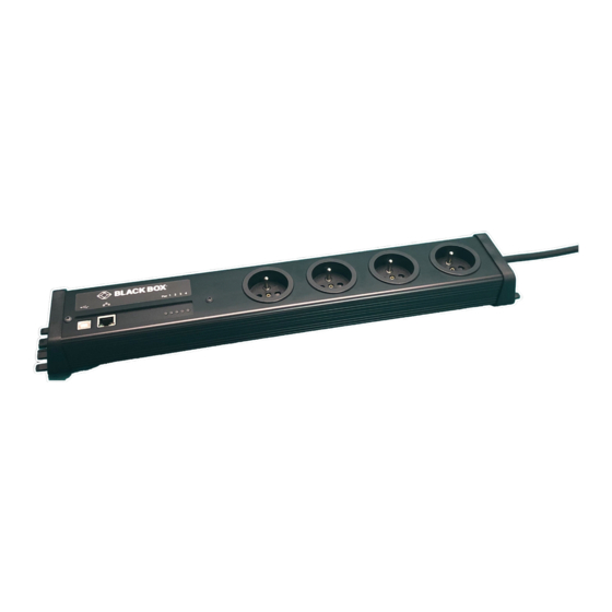
NEED HELP? LEAVE THE TECH TO US LIVE 24/7 TECHNICAL CHAPTER 1: DESCRIPTION SUPPORT 1.877.877.2269 1.1 DESCRIPTION PSE544 is an extension lead that enables remote power control over IP or locally through an USB Terminal connection. The built-in mini Web server allows individual control of the four sockets, using a browser. Its USB interface can be used to control the power outlets over a Terminal connection, such as a KVM Switch or console server. -
Page 7: Package List
NEED HELP? LEAVE THE TECH TO US LIVE 24/7 TECHNICAL CHAPTER 1: DESCRIPTION SUPPORT 1.877.877.2269 Network (RJ-45 Connector) 100 (LED) Auto-Sensing 10/100 Mbit/sec Ethernet Port Off = 10 Mbit/sec network connection On = 100 Mbit/sec network connection Link (LED) USB 2.0 USB port with Type-B connector. Off = Network connection not detected On = Network connection detected Flashing = the device is sending or receiving data... -
Page 8: Installation / Cabling
NEED HELP? LEAVE THE TECH TO US LIVE 24/7 TECHNICAL CHAPTER 2: INSTALLATION/CABLING SUPPORT 1.877.877.2269 2.1 INSTALLATION / CABLING Use the provided or any shielded RJ-45 network cable to connect your PSE544 to your network. Use appropriated three-wire power cords (two poles plus ground) to connect your electrical devices to the power outlets of the PSE544 unit. -
Page 9: Pse544 Network Settings
NEED HELP? LEAVE THE TECH TO US LIVE 24/7 TECHNICAL CHAPTER 3: NETWORK SETTINGS SUPPORT 1.877.877.2269 3.1 PSE544 NETWORK SETTINGS In order to use the PSE544 in your network, you must first configure its network parameters. Ask your network administrator for the parameters to use. There are three methods to configure the network parameters of the PSE544: 3.1.1 IP CONFIGURATION THROUGH THE LAN USING THE BB-FINDER PROGRAM This is the simplest and fastest configuration method if you use the Windows operating system. -
Page 10: Ip Configuration Through An Usb Terminal Connection
NEED HELP? LEAVE THE TECH TO US LIVE 24/7 TECHNICAL CHAPTER 3: NETWORK SETTINGS SUPPORT 1.877.877.2269 NOTE: To achieve the highest security level, disable the configuration using the Finder program after the first installation. DHCP: Check this box if you want to obtain the IP address, the subnet mask, and the default gateway for your PSE544 via DHCP. -
Page 11: Ip Configuration Through The Lan Using A Browser
NEED HELP? LEAVE THE TECH TO US LIVE 24/7 TECHNICAL CHAPTER 3: NETWORK SETTINGS SUPPORT 1.877.877.2269 Configuration menu ----------------------------------------------------------- NETWORK INTERFACE PARAMETERS: IP address on LAN is 192.168.100.200 LAN interface’s subnet mask is 255.255.255.0 IP address of default gateway to other networks is 0.0.0.0 IP address of primary DNS server is 0.0.0.0 IP address of secondary DNS server is 0.0.0.0 MISCELLANEOUS:... -
Page 12: General / Ip Configuration
NEED HELP? LEAVE THE TECH TO US LIVE 24/7 TECHNICAL CHAPTER 3: NETWORK SETTINGS SUPPORT 1.877.877.2269 3.1.4 GENERAL / IP CONFIGURATION This page enables you to define the PSE544’s IP parameters. FIGURE 3-2: IP CONFIGURATION DHCP Client enabled: Check this box if you want to obtain the IP address, the subnet mask, and the default gateway for your PSE544 via DHCP. -
Page 13: General / System Time
NEED HELP? LEAVE THE TECH TO US LIVE 24/7 TECHNICAL CHAPTER 3: NETWORK SETTINGS SUPPORT 1.877.877.2269 LOGOUT: Click “Logout” at the bottom of the page to exit the session without saving changes. DISCARD CHANGES: Click “Discard Changes” at the bottom of the page to discard all of the changes that you have made on this page. APPLY CHANGES: Click “Apply Changes”... -
Page 14: General / Smtp
NEED HELP? LEAVE THE TECH TO US LIVE 24/7 TECHNICAL CHAPTER 3: NETWORK SETTINGS SUPPORT 1.877.877.2269 Daylight Saving Time: If you want to set Daylight Saving dates, check this box and specify the date that you want to use. LOGOUT: Click “Logout”... - Page 15 NEED HELP? LEAVE THE TECH TO US LIVE 24/7 TECHNICAL CHAPTER 3: NETWORK SETTINGS SUPPORT 1.877.877.2269 SMTP Port This fields stores the SMTP Communication port to use; the default is 25. From (email Address) This field stores the email address that messages will appear to come from. The name can be 1 to 64 characters long, and it can contain alphanumeric characters.
-
Page 16: General / Snmp
NEED HELP? LEAVE THE TECH TO US LIVE 24/7 TECHNICAL CHAPTER 3: NETWORK SETTINGS SUPPORT 1.877.877.2269 3.1.7 GENERAL / SNMP The PSE544 provides a built-in SNMP (Simple Network Management Protocol) agent, which enables you to manage the PSE544 through SNMP-based network management systems. The PSE544 MIB file enables remote read out of the status of all power outlets and the values of all sensors (temperature, humidity, and ambient light). -
Page 17: General / Trigger
NEED HELP? LEAVE THE TECH TO US LIVE 24/7 TECHNICAL CHAPTER 3: NETWORK SETTINGS SUPPORT 1.877.877.2269 Read Community: This field stores the name that you want to assign to the Read Community field. The name can have 1 to 64 characters, and it can contain alphanumeric characters. - Page 18 NEED HELP? LEAVE THE TECH TO US LIVE 24/7 TECHNICAL CHAPTER 3: NETWORK SETTINGS SUPPORT 1.877.877.2269 FIGURE 3-5: TRIGGER Trigger Server enabled Check this box if you want to enable the Trigger function. NOTE: The Trigger function must be activated on both the emitter device (your device) and the target device (the remote Power Switch).
-
Page 19: General / Syslog
NEED HELP? LEAVE THE TECH TO US LIVE 24/7 TECHNICAL CHAPTER 3: NETWORK SETTINGS SUPPORT 1.877.877.2269 3.1.9 GENERAL / SYSLOG This page is used to define the address of two Syslog Servers. FIGURE 3-6: SYSLOG SETTINGS Primary Syslog Server Select this checkbox and specify the IP address or the hostname of your primary Syslog server. NOTE: If you use a hostname, the system must be able to resolve queries for the hostname into IP address, so you must configure a default gateway and at least one DNS server on the Network Settings Page, accessible through General/IP Configuration page. -
Page 20: General / Tools
NEED HELP? LEAVE THE TECH TO US LIVE 24/7 TECHNICAL CHAPTER 3: NETWORK SETTINGS SUPPORT 1.877.877.2269 3.1.10 GENERAL / TOOLS This page is used to: Š download and save the current settings of your PSE544 on your PC, Š upload an existing configuration file to your PSE544, ... -
Page 21: Settings / Accounts
NEED HELP? LEAVE THE TECH TO US LIVE 24/7 TECHNICAL CHAPTER 3: NETWORK SETTINGS SUPPORT 1.877.877.2269 3.1.11 SETTINGS / ACCOUNTS This page is used to create, activate, deactivate, modify, and delete up to 40 accounts: Š To activate or deactivate an account, check or uncheck the corresponding checkbox. ... - Page 22 NEED HELP? LEAVE THE TECH TO US LIVE 24/7 TECHNICAL CHAPTER 3: NETWORK SETTINGS SUPPORT 1.877.877.2269 User Name: This field stores the name that you want to assign to the user account. It can be from 1 to 32 characters long, and it can contain alphanumeric characters.
-
Page 23: Settings / Accounts / Hidden
NEED HELP? LEAVE THE TECH TO US LIVE 24/7 TECHNICAL CHAPTER 3: NETWORK SETTINGS SUPPORT 1.877.877.2269 DISCARD CHANGES: Click “Discard Changes” at the bottom of the page to discard all of the changes that you have made on this page. APPLY CHANGES: Click “Apply Changes”... - Page 24 NEED HELP? LEAVE THE TECH TO US LIVE 24/7 TECHNICAL CHAPTER 3: NETWORK SETTINGS SUPPORT 1.877.877.2269 Activated This check box must be checked to activate the Hidden Page Account. It enables temporary deactivation of this account while keeping all its settings for later use. The Hidden Page Account cannot be deleted. User Name In this field, enter the name that you want to assign to the Hidden Page Account.
- Page 25 NEED HELP? LEAVE THE TECH TO US LIVE 24/7 TECHNICAL CHAPTER 3: NETWORK SETTINGS SUPPORT 1.877.877.2269 Inputs/Outputs This field is used to add/remove Inputs or Outputs to/from the current account. To add an Input or Output to the current account, select the Input / Output that you want to add in the left field and click on the arrow button.
-
Page 26: Settings / Groups
NEED HELP? LEAVE THE TECH TO US LIVE 24/7 TECHNICAL CHAPTER 3: NETWORK SETTINGS SUPPORT 1.877.877.2269 Each Power Outlet individually supports three commands: On, Off, and Restart using following syntax: M0:Ox=[ON], [OFF], [RESTART] M0: ID of your Power Switch Ox: Outlet number of your Power Switch ON: ON command OFF: OFF command RESTART: Restart command... - Page 27 NEED HELP? LEAVE THE TECH TO US LIVE 24/7 TECHNICAL CHAPTER 3: NETWORK SETTINGS SUPPORT 1.877.877.2269 Š To delete an existing group, click on “Delete” for the corresponding device. Š To add or remove power outlets to/from an existing group, click on “Edit” for the corresponding device. ...
-
Page 28: Settings / Peripherals
NEED HELP? LEAVE THE TECH TO US LIVE 24/7 TECHNICAL CHAPTER 3: NETWORK SETTINGS SUPPORT 1.877.877.2269 Power Outlets: This field is used to add and remove power outlets to and from the group. To add power outlets to the group, press the <Ctrl> key and click on the power outlets for the Power Switch selected in the field above. - Page 29 NEED HELP? LEAVE THE TECH TO US LIVE 24/7 TECHNICAL CHAPTER 3: NETWORK SETTINGS SUPPORT 1.877.877.2269 FIGURE 3-15: LABEL DEFINITION The PSE544 automatically creates an ID Code to clearly identify each device. identifies the PSE544 device Name: This field stores the name that you want to assign to the selected device. It can be from 1 to 32 characters long, and it can contain alphanumeric characters.
- Page 30 NEED HELP? LEAVE THE TECH TO US LIVE 24/7 TECHNICAL CHAPTER 3: NETWORK SETTINGS SUPPORT 1.877.877.2269 Default Power-Up: In the drop-down list, for each power outlet, choose the default status to apply after power up. You can choose between: Š “On” if you want the corresponding power outlet to be always switched on after power up. ...
-
Page 31: Settings / Rules
NEED HELP? LEAVE THE TECH TO US LIVE 24/7 TECHNICAL CHAPTER 3: NETWORK SETTINGS SUPPORT 1.877.877.2269 3.1.15 SETTINGS / RULES The PSE544 is not only a Power Switch over IP, it also supports trigger-action programming, which means users can specify a system’s behavior as an event (trigger) and the appropriate action to be taken whenever this event occurs. The trigger and the action are part of different rules that can be easily configured with the mouse. -
Page 32: Settings / Rules - Schedule Rule
NEED HELP? LEAVE THE TECH TO US LIVE 24/7 TECHNICAL CHAPTER 3: NETWORK SETTINGS SUPPORT 1.877.877.2269 2. Timer Rule: This rule can be used to trigger user-specified actions according to a defined time table. This rule can be used to switch a power outlet, a group of power outlets, or a digital output on or off at a specified time and weekday(s) for a specified time. - Page 33 NEED HELP? LEAVE THE TECH TO US LIVE 24/7 TECHNICAL CHAPTER 3: NETWORK SETTINGS SUPPORT 1.877.877.2269 FIGURE 3-17: SCHEDULE RULE Activated This check box must be checked to activate the rule. It enables the rule to be temporarily deactivated while keeping all of its settings for later use.
- Page 34 NEED HELP? LEAVE THE TECH TO US LIVE 24/7 TECHNICAL CHAPTER 3: NETWORK SETTINGS SUPPORT 1.877.877.2269 Rule Type: In this drop-down list, choose “Schedule Rule” and then configure both the event and the actions to perform. Configuring the Event Schedule Action: Here you can define the time when the rule has to be executed.
- Page 35 NEED HELP? LEAVE THE TECH TO US LIVE 24/7 TECHNICAL CHAPTER 3: NETWORK SETTINGS SUPPORT 1.877.877.2269 Configuring the Action(s) Type of Action For the defined Event, you can choose and configure following actions: Set Outputs NOTE: This type of Action only appears if: Š...
- Page 36 NEED HELP? LEAVE THE TECH TO US LIVE 24/7 TECHNICAL CHAPTER 3: NETWORK SETTINGS SUPPORT 1.877.877.2269 Check this box if you want to send a message to a Syslog server. In the following drop-down list choose the facility and the severity of the message to send. Send Trap Message NOTE: This type of action appears and can be configured only if you have already specified at least one destination SNMP Server through General/SNMP page.
-
Page 37: Settings / Rules - Timer Rule
NEED HELP? LEAVE THE TECH TO US LIVE 24/7 TECHNICAL CHAPTER 3: NETWORK SETTINGS SUPPORT 1.877.877.2269 3.1.17 SETTINGS / RULES - TIMER RULE This rule can be used to trigger some actions according to a defined time table. For example, you could create a rule to switch off a power outlet every Friday at 6 p.m. and create another rule to switch it on again every Monday at 8 a.m. - Page 38 NEED HELP? LEAVE THE TECH TO US LIVE 24/7 TECHNICAL CHAPTER 3: NETWORK SETTINGS SUPPORT 1.877.877.2269 Rule Type In this drop-down list, choose Schedule Rule. Rules are used to control actions according to a specific event. To create a rule, you will first have to configure the chosen event and then choose the actions to perform.
-
Page 39: Settings / Rules - Ping Monitoring Rule
NEED HELP? LEAVE THE TECH TO US LIVE 24/7 TECHNICAL CHAPTER 3: NETWORK SETTINGS SUPPORT 1.877.877.2269 Each relay output can be switched to Open, Close, Pulse Open, or Pulse Close. If you choose Pulse open or Pulse close, you can also define a delay to be between 0 and 3,600 seconds. Š... - Page 40 NEED HELP? LEAVE THE TECH TO US LIVE 24/7 TECHNICAL CHAPTER 3: NETWORK SETTINGS SUPPORT 1.877.877.2269 FIGURE 3-19: PING MONITORING RULE Activated This check box must be checked to activate the Rule. It enables the temporary deactivation of a rule while keeping all of its settings for later use.
- Page 41 NEED HELP? LEAVE THE TECH TO US LIVE 24/7 TECHNICAL CHAPTER 3: NETWORK SETTINGS SUPPORT 1.877.877.2269 Rule Color: In this field, select one of the 48 standard colors that you want to use to highlight the rule when executed. To use your own color, enter the Hex value of the colour you want.
- Page 42 NEED HELP? LEAVE THE TECH TO US LIVE 24/7 TECHNICAL CHAPTER 3: NETWORK SETTINGS SUPPORT 1.877.877.2269 Configuring the Action(s) Type of Actions: For the defined event, you can choose and configure following actions: Set Outputs NOTE: This type of Action only appears if: Š...
- Page 43 NEED HELP? LEAVE THE TECH TO US LIVE 24/7 TECHNICAL CHAPTER 3: NETWORK SETTINGS SUPPORT 1.877.877.2269 Send Syslog Message NOTE: This type of Action can only be configured if you have already specified at least one destination Syslog Server through General/Log Settings page. Check this box if you want to send a message to a Syslog server.
-
Page 44: Settings / Rules - Scan Monitoring Rule
NEED HELP? LEAVE THE TECH TO US LIVE 24/7 TECHNICAL CHAPTER 3: NETWORK SETTINGS SUPPORT 1.877.877.2269 3.1.19 SETTINGS / RULES - SCAN MONITORING RULE This rule can be used to check if a specific protocol is available on a server (for example HTTP, FTP, Telnet, or POP). If the connection is possible, PSE544 knows that a server program is running there. - Page 45 NEED HELP? LEAVE THE TECH TO US LIVE 24/7 TECHNICAL CHAPTER 3: NETWORK SETTINGS SUPPORT 1.877.877.2269 Rule Name: In this field, enter the name that you want to give to the rule. The name can be from 1 to 32 characters long, and it can contain alphanumeric characters.
- Page 46 NEED HELP? LEAVE THE TECH TO US LIVE 24/7 TECHNICAL CHAPTER 3: NETWORK SETTINGS SUPPORT 1.877.877.2269 Configuring the Actions For the defined Event, you can choose and configure following actions: Set Outputs NOTE: This type of Action only appears if: Š...
- Page 47 NEED HELP? LEAVE THE TECH TO US LIVE 24/7 TECHNICAL CHAPTER 3: NETWORK SETTINGS SUPPORT 1.877.877.2269 Send Trap Message This type of action appears and can be configured only if you have already specified at least one destination SNMP Server through General/SNMP page. Check this/these box(es) and specify one or two SNMP addresses in the corresponding field if you want to send SNMP messages to one or two SNMP Servers.
-
Page 48: Settings / Rules - Trigger
NEED HELP? LEAVE THE TECH TO US LIVE 24/7 TECHNICAL CHAPTER 3: NETWORK SETTINGS SUPPORT 1.877.877.2269 3.1.20 SETTINGS / RULES - TRIGGER This rule is used to send a request over the Internet from your device to another device. The request sent by your device is used to trigger an action on the second device, for instance to remotely turn on or off a power outlet, to close or open a relay, or to send an alarm message (SNMP Trap, email, or Syslog). - Page 49 NEED HELP? LEAVE THE TECH TO US LIVE 24/7 TECHNICAL CHAPTER 3: NETWORK SETTINGS SUPPORT 1.877.877.2269 Rule Type In this drop-down list, choose Trigger Rule. Then configure the event and the actions to perform. Configuring the Event Magic word: In this field, enter the word that you want to use to trigger the corresponding action on a remote device. It can be from 1 to 32 characters long, and it can contain alphanumeric characters.
- Page 50 NEED HELP? LEAVE THE TECH TO US LIVE 24/7 TECHNICAL CHAPTER 3: NETWORK SETTINGS SUPPORT 1.877.877.2269 Rule to cancel This type of action only appears if you already have created a rule that you want to cancel. Select this checkbox and choose in the corresponding drop-down list the rule that you want to cancel. Send Magic to Your device has the possibility to send a Magic Word over IP to another device in order to remotely trigger an action.
-
Page 51: Settings / Associations
NEED HELP? LEAVE THE TECH TO US LIVE 24/7 TECHNICAL CHAPTER 3: NETWORK SETTINGS SUPPORT 1.877.877.2269 APPLY CHANGES Click “Apply Changes” at the bottom of the page to save changes. 3.1.21 SETTINGS / ASSOCIATIONS This page is used to configure the settings related to Safe Shutdown and Wake on LAN. It enables to create an Association of interfaces which can be implemented in Rules or used manually with your browser. - Page 52 NEED HELP? LEAVE THE TECH TO US LIVE 24/7 TECHNICAL CHAPTER 3: NETWORK SETTINGS SUPPORT 1.877.877.2269 This page is used to create, modify and delete an association. Click on “Add a New Association” on the right side of the page. A new page appears, allowing you to set all of the parameters. FIGURE 3-23: ADD A NEW ASSOCIATION Activated This check box must be checked to activate the association.
- Page 53 NEED HELP? LEAVE THE TECH TO US LIVE 24/7 TECHNICAL CHAPTER 3: NETWORK SETTINGS SUPPORT 1.877.877.2269 This delay is applicable only if the association does not have a power outlet. The delay can be set to be between 1 and 3,600 seconds.
-
Page 54: Misc / Control Panel
NEED HELP? LEAVE THE TECH TO US LIVE 24/7 TECHNICAL CHAPTER 3: NETWORK SETTINGS SUPPORT 1.877.877.2269 Group: NOTE: This type of action appears and can be configured only if you have already created at least one group through Settings/Groups tab. Š... -
Page 55: Misc / Rule Panel
NEED HELP? LEAVE THE TECH TO US LIVE 24/7 TECHNICAL CHAPTER 3: NETWORK SETTINGS SUPPORT 1.877.877.2269 3.1.23 MISC / RULE PANEL This page shows all of the rules that the administrator has created and activated. The rules which have been executed can also be highlighted in different colors according to the action’s emergency. -
Page 56: Power Outlet Control And Peripherals Status
NEED HELP? LEAVE THE TECH TO US LIVE 24/7 TECHNICAL CHAPTER 4: POWER OUTLET CONTROL AND PERIPHERALS SUPPORT 1.877.877.2269 4.1 POWER OUTLET CONTROL AND PERIPHERALS STATUS 4.1.1 VIA THE INTERNET USING A STANDARD BROWSER Start your Web browser and type the PSE544’s IP address. The browser displays the authentication dialog box. Enter a username and its corresponding password. -
Page 57: Through An Usb Connection
NEED HELP? LEAVE THE TECH TO US LIVE 24/7 TECHNICAL CHAPTER 4: POWER OUTLET CONTROL AND PERIPHERALS SUPPORT 1.877.877.2269 4.1.2 THROUGH AN USB CONNECTION The power outlets of the Power Switch-can be controlled using a simple ASCII protocol over an USB connection. Connect the USB interface of the Power Switch to an available USB port of your PC. -
Page 58: Through The Network Using Simple Commands In Your Own Program
NEED HELP? LEAVE THE TECH TO US LIVE 24/7 TECHNICAL CHAPTER 4: POWER OUTLET CONTROL AND PERIPHERALS SUPPORT 1.877.877.2269 Examples to control the Master: /P00=1 <ENTER> switch all the 4 power outlets ON /P00=0 <ENTER> switch all the 4 power outlets OFF /P03=r <ENTER>... -
Page 59: Troubleshooting / Restore Default Value / Update
NEED HELP? LEAVE THE TECH TO US LIVE 24/7 TECHNICAL CHAPTER 5: TROUBLESHOOTING, RESTORE, UPDATE SUPPORT 1.877.877.2269 6.1 TROUBLESHOOTING / RESTORE DEFAULT VALUE / UPDATE 5.1.1 RESTORE TO DEFAULT FACTORY SETTINGS Use an USB cable to connect the PSE544 to an USB port of your PC. Run a Terminal program. -
Page 60: Special Terminal Commands (/Help)
NEED HELP? LEAVE THE TECH TO US LIVE 24/7 TECHNICAL CHAPTER 5: TROUBLESHOOTING, RESTORE, UPDATE SUPPORT 1.877.877.2269 5.1.3 SPECIAL TERMINAL COMMANDS (/HELP) The user can send following Terminal commands over the USB interface: /viewlog Display the log file /initlog Clear the log file /initadminaccount Restore default administrator password /restorefactconf... -
Page 61: General Information
NEED HELP? LEAVE THE TECH TO US LIVE 24/7 APPENDIX A: GENERAL INFORMATION TECHNICAL SUPPORT 1.877.877.2269 A.1 GENERAL INFORMATION A.1.1 PING AND SCAN METHODS PSE544 has two methods to check whether a piece of IP equipment, such as a PC, server, router, or Webcam, is still alive: Address Pinging: The first method uses the well-known Ping command in which a request is sent to a specific IP address. -
Page 62: Technical Data
NEED HELP? LEAVE THE TECH TO US LIVE 24/7 TECHNICAL APPENDIX A: GENERAL INFORMATION SUPPORT 1.877.877.2269 A.1.2 TECHNICAL DATA TABLE 1-1. GENERAL SPECIFICATIONS SPECIFICATION DESCRIPTION Network standards IEEE 802.3, 10/100 BASE-T Network protocols TCP/IP, HTTP, RJ-45 connector for STP CAT5 xBus Network connection Max. - Page 63 NEED HELP? LEAVE THE TECH TO US LIVE 24/7 APPENDIX A: GENERAL INFORMATION TECHNICAL SUPPORT 1.877.877.2269 Š Failure on Power Input A of Satellite (number) Š Failure on Power Input B of Satellite (number) Severity Level 2, Critical: The following messages appear at severity 2: Š...
- Page 64 NEED HELP? LEAVE THE TECH TO US LIVE 24/7 TECHNICAL APPENDIX A: GENERAL INFORMATION SUPPORT 1.877.877.2269 Š Dry Contact Output (number) has been closed Š Session opened by user “name” Severity Level 7, Debug: PSE544 doesn’t generate Severity Level 7. 1.877.877.2269 BLACKBOX.COM...
-
Page 65: Fcc Statement
NEED HELP? LEAVE THE TECH TO US LIVE 24/7 APPENDIX B: REGULATORY INFORMATION TECHNICAL SUPPORT 1.877.877.2269 B.1 FCC STATEMENT This equipment has been tested and found to comply with the regulations for a Class B digital device, pursuant to Part 15 of the FCC Rules. These limits are designed to provide reasonable protection against harmful interference when the equipment is operated in a commercial environment. -
Page 66: Nom Statement
NEED HELP? LEAVE THE TECH TO US LIVE 24/7 TECHNICAL APPENDIX B: REGULATORY INFORMATION SUPPORT 1.877.877.2269 B.4 NOM STATEMENT 1. Todas las instrucciones de seguridad y operación deberán ser leídas antes de que el aparato eléctrico sea operado. 2. Las instrucciones de seguridad y operación deberán ser guardadas para referencia futura. 3. -
Page 67: Disclaimer
C.1 DISCLAIMER Black Box Corporation shall not be liable for damages of any kind, including, but not limited to, punitive, consequential or cost of cover damages, resulting from any errors in the product information or specifications set forth in this document and Black Box Corporation may revise this document at any time without notice. - Page 68 NEED HELP? LEAVE THE TECH TO US LIVE 24/7 TECHNICAL SUPPORT 1.877.877.2269 © COPYRIGHT 2022. BLACK BOX CORPORATION. ALL RIGHTS RESERVED. PSE544-DE-R2_PSE544-FR-R2_USER_REV2.PDF...
Need help?
Do you have a question about the PSE544-DE-R2 and is the answer not in the manual?
Questions and answers