
Related Manuals for Black Box PSE508MA


Summary of Contents for Black Box PSE508MA
-
Page 1: Power Switch
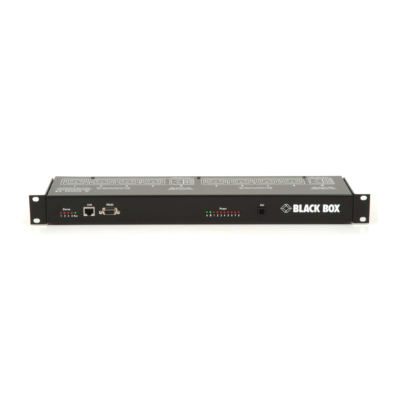
OCTOBER 2006 PSE508MA-XX PSE508SA-XX Power Switch Master/Satellite Twin 8-Port SUPPORT FREE technical support... - Page 2 EN55022:1998. PSE508MA/SA PSE508MA/SA is a couple of power control units made of a Master named Power Switch Master Twin and a satellite named Power Switch Satellite Twin. Power Switch Master Twin is a power control unit with a built-in Web server, an Ethernet and a serial RS232 connection.
-
Page 3: Table Of Contents
Contents Contents Chapters 1. Safety instructions___________________________________________________________________ 2 2. Installation_________________________________________________________________________ 4 2.1 Connecting Power Switch Master Twin ________________________________________________ 4 2.2 Connecting Power Switch Satellite Twin _______________________________________________ 5 3. Configuration of the Power Switch Master Twin ____________________________________________ 6 3.1 Configuration using the Power Switch Finder program ____________________________________ 7 3.2 Configuration using a Terminal connection _____________________________________________ 9 4. -
Page 4: Safety Instructions
POWER SWITCH PSE508MA & PSE508SA 1. Safety instructions To be read before use! Remark: In the following instructions "Power Switch device" is used for both devices Power Switch Master Twin and Power Switch Satellite Twin. • The Power Switch devices can only be installed by qualified people with the following installation and use instructions. - Page 5 CHAPTER 2: Installation • The power outlets of the Power Switch devices are not circuit breakers! If you want to intervene on equipment connected to an Power Switch device you must disconnect this equipment from the Power Switch device. • The Power Switch devices contain potentially hazardous voltages. Do NOT attempt to disassemble them.
-
Page 6: Installation
POWER SWITCH PSE508MA & PSE508SA 2. Installation The Power Switch Master Twin has a built-in Web server, an Ethernet and a serial interface. It can be used as a stand-alone device to control over IP eight IEC power sockets. The number of controlled sockets can be extended to 16, 24, 32 or 40 by cascading 1 to 4 Power Switch Satellite. -
Page 7: Connecting Power Switch Satellite Twin
CHAPTER 2: Installation 2.2 Connecting Power Switch Satellite Twin 1. Connect the supplied RJ9 link-up cable to the RJ9 Out connector of the Master and to the RJ9 In connector of the Satellite. To cascade several Satellites, link RJ9 Out connector to RJ9 In connector of the next satellite. 2. -
Page 8: Configuration Of The Power Switch Master Twin
POWER SWITCH PSE508MA & PSE508SA 3. Configuration of the Power Switch Master Twin To use the Power Switch Master Twin on your network, you must first configure its network parameters. Ask your network administrator for the parameters to use. There are two different methods to configure the Power Switch Master Twin: Method 1: Through a network using the Power Switch Finder Program (on the delivered CD). -
Page 9: Configuration Using The Power Switch Finder Program
CHAPTER 3: Configuration 3.1 Configuration using the Power Switch Finder program Remarks: The Power Switch Master Twin and the PC used to configure it have to be connected on the same segment of the network. The protocol of this program cannot be routed so it cannot be used to configure the Power Switch through a WAN or the Internet. - Page 10 POWER SWITCH PSE508MA & PSE508SA General Tab This tab is used: • to define all the network parameters of the Power Switch Master Twin (IP Address, Subnet Mask, Default Gateway and Port Number). • to permit or deny the configuration using the Power Switch Finder program for security reasons.
-
Page 11: Configuration Using A Terminal Connection
CHAPTER 3: Configuration 3.2 Configuration using a Terminal connection The RS232 serial port of the Power Switch Master Twin can be used to control its power socket and to configure its Web server. To configure the Web server using a PC and a Terminal connection: 1. - Page 12 POWER SWITCH PSE508MA & PSE508SA 5. Press the <TAB> key on your keyboard. The Configuration menu appears on your screen and the Power Switch Master Twin is now in the Configuration mode. Follow the menu to configure the Web server of your Power Switch Master Twin.
- Page 13 CHAPTER 3: Configuration MAIN CONFIGURATION MENU The Main menu of the configuration mode displays all the commands that can be used. • All commands start with the character slash «/» (ex.: type the command /NP to go to the Network Parameters settings menu. •...
- Page 14 POWER SWITCH PSE508MA & PSE508SA NETWORK PARAMETERS SETTINGS MENU Command /NP This Menu is used to configure all network parameters (IP Address, Subnet Mask, Gateway and Port) and to permit or prevent the configuration over a local area network using the special Power Switch Finder program.
- Page 15 CHAPTER 3: Configuration PASSWORD SETTINGS MENU Command /PS This Menu is used to configure the names and the corresponding passwords for the administrator and all the users. PASSWORDS SETTINGS Administrator Users Device 1 Users Device 2 Users Device 3 Users Device 4 Users Device 5 Enter Selection or <ESC>...
- Page 16 POWER SWITCH PSE508MA & PSE508SA GROUP, DEVICE AND SOCKET NAMES SETTINGS Command /NS This Menu is used to attribute a label to a group of Power Switch, a label to each Power Switch device and a label to each power socket.
- Page 17 CHAPTER 3: Configuration DEVICE PARAMETERS SETTINGS Command /DP This Menu is used to: • configure an Email address to which the user can manually send a message in case of problem, • define the function modus of each Power Switch device (Single mode or Twin mode), Single mode enables...
- Page 18 POWER SWITCH PSE508MA & PSE508SA SOCKET RESTART DELAY SETTINGS Command /RD This Menu is used to define the restart delay for all the power sockets. SOCKET RESTART DELAY SETTINGS Delay before Restart (sec) Enter Selection or <ESC> to exit >...
- Page 19 CHAPTER 3: Configuration IP SECURITY SETTINGS Command /IS This Menu is used to define IP addresses or IP ranges that are authorized or not to access the Web Server of the Power Switch Master Twin. See § 4 for all details. IP SECURITY SETTINGS Mask #1 0.0.0.0...
- Page 20 POWER SWITCH PSE508MA & PSE508SA RESTART THE DEVICE Command /RS This Menu is used to restart the Power Switch Master Twin. This function is needed: • to take into account changes of network parameters (command /NP), • to leave the serial configuration mode and return to the command mode.
-
Page 21: Security Parameters
CHAPTER 4: Security parameters 4. Security parameters Explanations about masks settings : • Each mask can be an IP Address or a range of IP Addresses. • Each mask allows you to permit or deny access to the Web server of the Power Switch Master Twin for specific addresses or ranges of addresses. - Page 22 POWER SWITCH PSE508MA & PSE508SA Example 3: ⇒ Permit access only to IP addresses beginning with 192 ⇒ Deny access to IP address 192.168.001.010 Mask IP Address Permit Deny Activated 192.168.001.010 192.255.255.255 255.255.255.255 Example 4: ⇒ Permit access to IP addresses beginning with 192 ⇒...
-
Page 23: Serial Port Configuration
CHAPTER 5: Serial port configuration 5. Serial port configuration Power Switch Master Twin Connector: SUB-D9 female connector Pin configuration Configuration parameters Pin 2 = TxD (transmit data to the PC) Speed: 9600 bauds Pin 3 = RxD (receive commands) Parity: Pin 5 = GnD Format: 8 bits... -
Page 24: Control The Power Outlets
POWER SWITCH PSE508MA & PSE508SA 6. Control the power outlets 6.1 Control the power outlets through a Web browser 1. Start your Web browser. Type the IP address of your Power Switch Master Twin. The browser displays the authentication dialog box. - Page 25 CHAPTER 6: Control the power outlets Default Configuration of the Power Switch Master Twin IP address 192.168.100.100 Administrator Name : admin Subnet mask 255.255.255.0 Administrator Password : admin Gateway no address Port...
-
Page 26: Control The Power Outlets Through A Serial Connection
POWER SWITCH PSE508MA & PSE508SA 6.2 Control the power outlets through a serial connection The power sockets of the Power Switch Master Twin and the Power Switch Satellite Twin can be controlled using a simple ASCII protocol over an RS232 serial connection. - Page 27 CHAPTER 6: Control the power outlets The syntax of the command line is: Pxy=z Parameter Value Function 1 to 5 represents the number of the Power Switch: 1 means Power Switch Master Twin 2 to 5 means the corresponding connected Satellite means that all the sockets have to be controlled together 1 to 8 indicates the number of the socket you want to control...
- Page 28 POWER SWITCH PSE508MA & PSE508SA ONTROL THE POWER SOCKETS OF A OWER WITCH ATELLITE WIN OR SEVERAL ATELLITES CONNECTED TOGETHER In this case, you have to make a special serial cable as indicated by the drawing in §7 or contact your dealer to order one.
-
Page 29: Technical Data
CHAPTER 7: Technical data 7. Technical data 7.1 Power Switch Master Twin Network standards IEEE 802.3, 10BASE-T Network protocols TCP/IP, HTTP RJ-45 connector for UTP CAT5 Network connection Maximal network cable length 100 meters (cable not included) RS232, SUB-D 9 female Serial connection Nominal input voltage 230 V/50Hz... -
Page 30: Power Switch Satellite Twin
POWER SWITCH PSE508MA & PSE508SA 7.2 Power Switch Satellite Twin Serial connection RS232, SUB-D 9 female Nominal input voltage 230 V/50Hz IEC-320 Input power socket Output voltage 230 V/50Hz IEC-320 Output power socket Maximum total current 2 x 10 A... - Page 31 © Copyright 2006. Black Box Corporation. All rights reserved. BLACK BOX Network Services...
Need help?
Do you have a question about the PSE508MA and is the answer not in the manual?
Questions and answers