
Subscribe to Our Youtube Channel
Related Manuals for Black Box PSE544


Summary of Contents for Black Box PSE544
-
Page 1: Power Switch
May 2011 PSE544-XX Power Switch Cabinet 4-Port New Generation SUPPORT FREE technical support... - Page 2 This product carries the CE mark to indicate compliance with the European Directive on Electromagnetic Compatibility (89/336/EEC). It has been tested to EN55024:1998 and EN55022:1998. PSE544 The Power Switch is an extension lead that enables you, through an Ethernet 10Base-T network, to switch on or off the power supply of any electric device.
-
Page 3: Table Of Contents
Power Switch Cabinet User's Guide Chapters Safety instructions: To be read before use! ______________________________________________________ 2 1. Description _____________________________________________________________________________ 3 1.1. Diagram ____________________________________________________________________________ 4 1.2. Package List ________________________________________________________________________ 5 2. Installation _____________________________________________________________________________ 6 3. Configuration ___________________________________________________________________________ 7 3.1. Configuration through the LAN using the Finder program _____________________________________ 7 3.2. -
Page 4: Safety Instructions: To Be Read Before Use
Power Switch Cabinet 4-port New Generation Safety instructions: To be read before use! The Power Switch Cabinet devices can only be installed by qualified people with the following installation and use instructions. The manufacturer disclaims all responsibility in case of a bad use of the Power Switch Cabinet devices and particularly any use with equipments that may cause personal injury or material damage. -
Page 5: Description
An internal Real Time Clock enables to trigger scheduled actions and timestamp all events (logs, SNMP traps and Syslog events). Power Switch PSE544 is more than a simple power strip. It offers IP device monitoring with automatic reboot function in case of lock-up. -
Page 6: Diagram
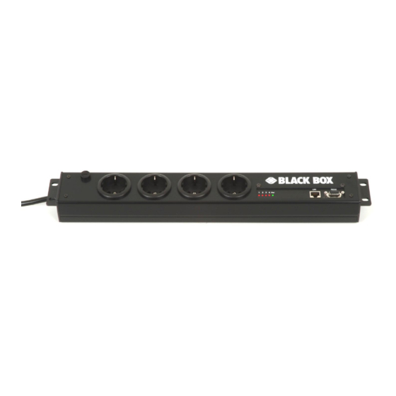
Power Switch Cabinet 4-port New Generation 1.1. Diagram Power input câble 4 power outlets 5 LEDs 230 VAC – 10 Amp 1 - 4 = Status of outlets 1 - 4 Pwr = Power RJ45 Connector SUB-D9F Connector Terminal connection 1 2 3 4 Pwr (LEDs) Red. -
Page 7: Package List
1.2. Package List The following items are included: 1 extension lead, 19" rack mountable, 1 serial cable SUB-D 9 points male / female, 1 RJ45 cable, male / male. CD including this user guide and the Power Switch Finder program. In option: wall mounting kit with 2 metal brackets, 4 cage nuts, washer and screws. -
Page 8: Installation
Power Switch Cabinet 4-port New Generation 2. Installation Remark: Make sure that the Power Switch is powered off. Connection instructions 1. Use a shielded RJ45 network cable to connect your Power Switch to the network. 2. Use appropriated three-wire power cords (two poles plus ground) to connect your electrical devices to the Power Switch unit. -
Page 9: Configuration
3. Open the File menu and choose CONFIGURE (or click on the second left button in the tool bar) to configure the network parameters. This page enables to define all IP parameters of the Power Switch PSE544 device and displays the version of the Firmware. The HTTP protocol is enabled and the Finder program is authorized at factory settings. - Page 10 Use of DHCP (Dynamic Host Configuration Protocol) requires a DHCP host to be set up on the network. IP Address: IP address of the Power Switch PSE544, default is 192.168.100.200. Subnet Mask: Subnet Mask of the Power Switch PSE544, default is 255.255.255.0.
-
Page 11: Configuration Through An Rs232 Terminal Connection
3.2. Configuration through an RS232 Terminal connection 1. Use the provided RS232 cable to connect the Power Switch PSE544 to an available serial port of your PC. 2. Run a Terminal program such as Windows HyperTerminal or the Micro Terminal program on the CD. -
Page 12: Restore To Default Factory Settings
Power Switch Cabinet 4-port New Generation 3.2.2. Restore to default factory settings If you want to restore the Power Switch to factory settings, you can reset it to default value using following procedure: 1. Use the supplied RS232 cable to connect the Power Switch-to an available serial port of your PC. 2. -
Page 13: Configuration Through The Lan Using A Standard Browser
2. Enter the administrator name and password (default for both = admin) 3. The home page appears, allowing you to configure all settings of your Power Switch PSE544. 3.3.1. General / IP configuration This page enables you to define all the IP parameters of the Power Switch PSE544. - Page 14 Finder Program enabled: The Network parameters of the Power Switch PSE544 can also be configured through a Local Area Network using the provided Finder Program. It is a very simple and fast configuration method if you use Windows as operating system.
-
Page 15: General / System Time
3.3.2. General / System time The system time of the Power Switch PSE544 is used for synchronizing scheduling actions and to timestamp SNMP traps, Syslog information and internal logs. The system time can be set manually with the browser time of the connected computer or can be automatically synchronized with one or two NTP timeservers. -
Page 16: General / Snmp
Trap Community: Check this box if you want to configure the Power Switch PSE544 SNMP agent to send traps to a community. In the following field, enter the name you want to give to the Trap Community. The name can be from 1 to 64 characters long, and can contain alphanumeric characters. -
Page 17: General / Tools
Click this button if you want to restore the factory default settings. Save MIB: Click this button if you want to download the Power Switch PSE544 MIB file onto your local hard drive. LOGOUT: Click "Logout" at the bottom of the page to exit the session without saving changes. -
Page 18: Settings / Accounts
Power Switch Cabinet 4-port New Generation 3.3.5. Settings / Accounts 3.3.5.1 Settings / Accounts This page is used to create, activate, deactivate, modify and delete up to 40 accounts. - To activate or deactivate an account, check or uncheck the corresponding checkbox. - To modify an account, click on "Edit"... - Page 19 Device: In this drop-down list, choose a device from which you want to add Inputs or Outputs to the current account. Inputs/Outputs: This field is used to add/remove Inputs or Outputs to/from the current account. To add Inputs or Outputs to the current account, press the Ctrl key and click on the Inputs/Outputs of the device selected in the previous field.
-
Page 20: Settings / Accounts / Hidden Page Account
Power Switch Cabinet 4-port New Generation 3.3.5.2 Settings / Accounts / Hidden Page account This account is intended for developers who want to implement the power outlet control in own programs. If activated, they can access to a special page named hidden.htm and control individually the power outlets using simple commands. - Page 21 Device In this drop-down list, choose the device from which one you want to add Inputs or Outputs to the current account. Inputs/Outputs - This field is used to add/remove Inputs or Outputs to/from the current account. - To add an Input or Output to the current account, select the Input / Output you want to add in the left field and click on the Arrow button, the selected Input / Output will then appear in the right field.
-
Page 22: Settings / Groups
Group Id: The Power Switch PSE544 automatically creates an ID Code to clearly identify each group of power outlets. All the ID Codes used to identify groups start with the letter "G". - Page 23 Click "Apply Changes" at the bottom of the page to save changes.
-
Page 24: Settings / Peripherals
Power Switch Cabinet 4-port New Generation 3.3.7. Settings / Peripherals This page enables to label the device, the 4 power outlets of the Power Switch 4 and the shutdown function. Names of up to 32 alphanumeric characters in length are supported and appear in log files, Syslog messages and SNMP traps to avoid confusions. - Page 25 Default Power-Up: In the drop-down lists, choose for each power outlet the default status to apply after power-up. You can choose between: - "On" if you want the corresponding power outlet to be always switched On after power-up. - "Off" if you want the corresponding power outlet to be always switched Off after power-up. - "Last Status"...
-
Page 26: Settings / Rules
Power Switch Cabinet 4-port New Generation 3.3.8. Settings / Rules Rules are used to control actions according to a specific event. For example, you can define a rule to switch a power outlet OFF and send an alert message using different methods like SNMP or Syslog when a temperature, humidity, ambient light or current exceeds a predefined value or when a contact is open. - Page 27 This rule is used to control actions according to the response to a Ping command. This rule can be used to check if a computer or any IP device is connected to the network. If the host doesn't reply, the Power Switch PSE544 can automatically restart the powered device. 4. Scan Monitoring Rule: This rule is used to control actions according to the response to a Scan command.
-
Page 28: Settings / Rules - Schedule Rule
Rule ID: The Power Switch PSE544 automatically creates an ID Code to clearly identify each rule. All the ID Codes used to identify rules start with the letter "R" followed by a number from 1 to 32. If you delete a rule in the middle of the Rule list, the number of this rule will only be used again if no other rule is available. - Page 29 Stop Time Defines what time the rule ends. - End Time must be greater than or equal to Start Time. - If the rule has to be executed only once at the selected weekday, enter the same value for Start Time and End Time.
-
Page 30: Settings / Rules - Timer Rule
Power Switch Cabinet 4-port New Generation 3.3.8.2. Settings / Rules - Timer Rule This rule used trigger some actions according defined time table. For instance, you could create a rule to switch OFF a Power Outlet every Friday at 6 PM and create another rule to switch the Power Outlets ON again every Monday at 8 AM. - Page 31 Type of Action For the Event defined above, you can choose and configure following actions: Set Group: This type of action appears and can be configured only if you have already created at least one group (Settings/Groups Tab). Check this box and in the corresponding drop-down list choose the power outlet group the rule will apply to. In the next corresponding drop-down list, choose the action to execute.
-
Page 32: Settings / Rules - Ping Monitoring Rule
Rule ID: The Power Switch PSE544 automatically creates an ID Code to clearly identify each rule. All the ID Codes used to identify rules start with the letter "R" followed by a number from 1 to 32. If you delete a rule in the middle of the Rule list, the number of this rule will only be used again if no other rule is available. - Page 33 The number can be set between 0 and 255. Type of Actions: For the Event defined above, you can choose and configure following actions: Set Group: This type of action appears and can be configured only if you have already created at least one group (Settings/Groups Tab).
-
Page 34: Settings / Rules - Scan Monitoring Rule
Rule ID: The Power Switch PSE544 automatically creates an ID Code to clearly identify each rule. All the ID Codes used to identify rules start with the letter "R" followed by a number from 1 to 32. If you delete a rule in the middle of the Rule list, the number of this rule will only be used again if no other rule is available. - Page 35 Delay before First Request after Action: In this field, define the time in seconds before restarting the monitoring after the reboot action. The delay can be set between 30 and 65535 seconds. Maximum Number of Actions In this field, define the maximum number of actions. The number can be set between 0 and 255.
-
Page 36: Settings / Shutdowns
Power Switch Cabinet 4-port New Generation 3.3.9. Settings / Shutdowns This power switch supports shutdown facilities of 1 server via its Serial RS232 interface. - To remove an existing Shutdown association, click on "Delete" of the corresponding rule. - To modify a Shutdown rule, click on "Edit" of the corresponding rule. This page is used to create, modify and delete a Shutdown Association. - Page 37 Group: This type of action appears and can be configured only if you have already created at least one group (Settings/Groups Tab). In this field, choose the group of power outlets which will be used for the Shutdown rule. - To select a group, select the output you want to add in the left field and click on the Arrow button, the output will then appear in the right field.
-
Page 38: Misc / Control Panel
Power Switch Cabinet 4-port New Generation 3.3.10. Misc / Control Panel This page is very helpful for the administrator because it gives a complete overview of all the power outlets. He can control all the power outlets of the Power Switch. -
Page 39: Misc / Rule Panel
3.3.11. Misc / Rule Panel This page shows all the rules the administrator has created and activated. The rules which have been executed can also be highlighted in different colours according to the emergency of the action. The highlight colours can be customized during the creation of the rule (Settings/Rules Page). -
Page 40: Misc / Log
Power Switch Cabinet 4-port New Generation 3.3.12. Misc / Log The log file keeps a running log of events and activities occurring on the device. The logs are automatically cleared when the device is rebooted. The file will display 10 recent logs. -
Page 41: Misc / Log Settings
3.3.13. Misc / Log Settings This page allows you to configure the logs. The Log file is used by the system to record actions, warnings, errors and problems. It is often quite useful to discover the causes of tricky problems. The messages recorded in the log file and sent as copy to a Syslog server are classified into 8 severity levels (Emergency, Alert, Critical, Error, Warning, Notice, Informational and Debug). -
Page 42: Power Outlet Control
- control all the power outlets and all the power outlet groups of Power Switch. If you log in as a user (Power Switch PSE544 handles up to 40 accounts), you will be able to: - control individually all the power outlets and all the power outlet groups for which you have the rights. -
Page 43: Through A Serial Connection
4.2. through a serial connection The power outlets of the Power Switch can be controlled using a simple ASCII protocol over an RS232 serial connection. 1. Use the supplied RS232 serial cable to connect the Power Switch-to an available serial port of your PC. 2. -
Page 44: Through The Network Using Simple Commands In Your Own Program
Power Switch Cabinet 4-port New Generation 4.3. through the network using simple commands in your own program Developers who want to implement the power outlet control in own programs can access to a special page named hidden.htm and control individually the power outlets using simple commands. To configure the Hidden Page Account, go to Settings / Accounts. - Page 45 Groups This field appears only if at least one group has already been created. To create a group, go to the Settings/Groups Page. - To add an existing group of Power Outlets to the current account, select the group you want to add in the left field and click on the Arrow button, the group will then appear in the right field.
- Page 46 Power Switch Cabinet 4-port New Generation Controlling Power Outlets Only Power Outlets which have been selected can be controlled over the Hidden Page. To select Power Outlets, go to the "Settings/Accounts" page and edit the Hidden Page Account. In the Inputs/Outputs field, selected the Power Outlets you want to control and click on the Arrow button next to the Inputs/Outputs field.
-
Page 47: Appendix
Message Protocol) if an IP device is available on the network. If the system reacts to this request, Power Switch PSE544 knows that the TCP/IP connection is established. If the system does not react to one or several requests, Power Switch PSE544 can automatically switch the device off and after a specified delay switch it again on (Reboot function). -
Page 48: Technical Data
Power Switch Cabinet 4-port New Generation 5.2. Technical Data Network standards: IEEE 802.3, 10 / 100 BASE-T Network protocols: TCP/IP, HTTP Network connection: RJ-45 connector for STP CAT5 Max. network cable length 100 meters Serial connection: RS232, SUB-D 9 female Operating temperature: 0°C to +40°C Operating humidity:... -
Page 49: Syslog Messages: Severity Level Definitions
Severity Level 1, Alert: The following messages appear at severity 1: - Settings have been reinitialized through the serial connection - Power Switch PSE544 does not respond - Failure on Power Input Severity Level 2, Critical: The following messages appear at severity 2: - "file"... - Page 50 Power Switch Cabinet 4-port New Generation © Copyright . Black Box Corporation. All rights reserved.
Need help?
Do you have a question about the PSE544 and is the answer not in the manual?
Questions and answers