
Related Manuals for Huazheng HZ-9003C


Summary of Contents for Huazheng HZ-9003C
- Page 1 HZ-9003C Multifunctional Partial Discharge Tester Huazheng Electric Manufacturing(Baoding) Co,.Ltd...
- Page 2 (0312) 6775656 to tell you to serve you at all times- Baoding Huazheng Elect ric Manufact ur ing Co. , Lt d. , our company will def initely make you satisf ied !
-
Page 3: Table Of Contents
Contents I.Adoption standard.........................1 II.Operation Notice.......................... 1 III.Overview............................1 IV.Measurement Procedures......................9 VI.Maintenance..........................24 VII.Packing List..........................25... -
Page 4: I.adoption Standard
5.After testing, please turn off the power and then charge the device. III.Overview HZ-9003C multifunctional partial discharge tester is used for on-line detection and location of partial discharge of HV equipment, which is designed based on our many years experiences in the partial discharge measuring fields. - Page 5 HZ-9003C Multifunctional Partial Discharge Tester include: device host 、 special partial discharge detection software、TEV sensor (TEV) 、ultrasonic sensor (USS)、ultrasonic concentrator (ELTW) 、high frequency CT (HFCT) 、UHF sensor (UHF) 、earphone and connecting wire.
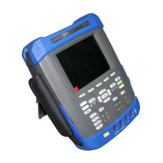
- Page 6 The Multifunctional Partial Discharge Tester main computer is divided with several function areas, according to the above number indications, 1. Wave display 2. F1- F5 Menu Buttons 3. Power indicator 4. MEAS: measurement menu 5. AUTORANGE: Auto 6. MENU OFF: Menu off 7.
- Page 7 3.2 Charge Main Tester The main tester should be charged when first use, the fully-charged time is 7 hours. The charging time will reduce if the tester is partially charged. The charging will be stopped if the battery is fully charged. The charging status is indicated by the charging light at the panel.
- Page 8 The Multifunctional Partial Discharge Tester host is at automatic mode and collecting wave without trigger. The Multifunctional Partial Discharge Tester host is continuously collecting wave data by scanning method and displaying the wave data. ● The Multifunctional Partial Discharge Tester host stops wave data collection. The Multifunctional Partial Discharge Tester host has completed the single sequence acquistion.
- Page 9 2. Menu: Press” Menu” button to start the menu bar, then conduct settings per the testing requirement. Discharge detect: Press F1 key to select output discharge signals circularly, then setup the signal output type per the detection requirement. “TEV” Output ground wave signal “USS”...
- Page 10 channel selection is CH1(CH2). 2) Setting: Press” setting” F2 key to activate the current channel setting options. Output voltage: Set output voltage for the sensors of the equipment which is to be tested. Press “ output voltage” F1 key to open the output voltage, press F1 key once to close the voltage.
- Page 11 Press the direction keys to select number, and then press the middle Enter button for confirmation, after that press the unit button, the green color setting is changed to the setting data. Traffic light unit is aligned with the pre-set unit. Press Cancel key to interrupt settings, the color will not change.
-
Page 12: Iv.measurement Procedures
When select “ single trigger” mode, the Multifunctional Partial Discharge Tester host can display the waves only after first trigger. When trigger mode is selected as “ single trigger”, the channel display will show” single”. When trigger mode is selected as “ automatic” or “ normal”, the channel display will show “... - Page 13 Composite TEV sensor wiring 2. Tester setting Open the tester, press and select CH1 to choose current channel to Channel1. Press “menu” button and then press F1 Key to select the” discharge detect” to TEV. Press F2 key to setup “output voltage” and “unit”. When use composite TEV sensors for detection the output voltage must be required.
- Page 14 Non discharge signals With discharge signals When the discharge signal detected by the switchgear cabinet PD tester is too large, the display screen data will change into red, the sensor is saturated at this time. Sensor saturated Background noise Instantaneous grounding voltage may occur outside of the switchgear cabinet due to the electromagnetic signal sources.
- Page 15 the metal bodies, otherwise it will affect the self-test. In order to make measurement, the TEV sensor shall be vertically parallel to the metal body to be measured. Once the tester is at continuous measurement mode, the readings will be display immediately. But if the TEV sensor is removed from the metal body, then the readings will not be displayed at the screen.
- Page 16 4.2 High Frequency current transformer measurement (Mainly measure transformer inside partial discharge) 1. High frequency current transformer connection Use BNC-BNC cable to connect to the tester CH1 channel BNC port, the other end to the high frequency current transformer BNC end. High frequency current transformer connection 2.
- Page 17 AUTORANGE Open The tester will be then at automatic trigger state, the Channel 1 screen will display the current high frequency current transformer testing discharge signals . Non-discharge Signals with discharge signals When the discharge signal is too large ,the value at the screen will then turn red, at this moment the sensor is in saturation state.
- Page 18 Close After the testing, press” AUTORANGE” key to close automatic trigger till the key light is off. After closing the automatic trigger, Press” Menu off” to close the menu bar if the menu bar is popping-up. AUTORANGE Close 4.3 Ultrasonic Measurement (Mainly support the measurement of transformer inside partial discharge) 1.
- Page 19 2.Tester settings Open the tester, press and select the current channel to CH1, Press” MENU” key, then press F1 key to select “ discharge test” as HFCT, press F2 Key to set” output voltage” and “ unit”. When use ultrasonic sensor to conduct measurement it would require output voltage.
- Page 20 The tester will be then at automatic trigger state, the Channel 1 screen will display the current ultrasonic sensor testing discharge signals . Non-discharge Signals with discharge signals When the discharge signal is too large ,the value at the screen will then turn red, at this moment the sensor is in saturation state.
- Page 21 After the testing, press” AUTORANGE” key to close automatic trigger till the key light is off. After closing the automatic trigger, Press” Menu off” to close the menu bar if the menu bar is popping-up. AUTORANGE Close 4.4 Ultra-High frequency measurement (Mainly measure GIS internal Partial Discharge) 1.
- Page 22 3.Start measurement Press” AUTORANGE” Key till the light is on to green, then the tester is about to measure. AUTORANGE Open The tester will be then at automatic trigger state, the Channel 1 screen will display the current ultra-high frequency sensor testing discharge signals . Non-discharge Signals with discharge signals When the discharge signal is too large ,the value at the screen will then turn red, at this...
- Page 23 4. Save To save the current discharged signal, You need to prepare a USB disk to store the graphics. Save Graphics: Press” SAVE/RECALL”, open the save/recall menu bar, press “ graphic” F5 key to save, the discharge signals will be stored at the USB. After testing, plug the USB at the PC, you can read the stored discharge signal waves at PC.
- Page 24 port, the BNC end is connected to the ultrasonic sensor BNC port. Two channels tester connection Main tester settings Open the main tester, Press CH1 to select the current channel at channel 1, then press” Menu” key and F1 key to set “ discharge test” as TEV, Press F2 key to set “...
- Page 25 The tester will be then at automatic trigger state, the Channel1 screen will display the current composite TEV sensor testing signals, the channel2 screen will display the current ultrasonic sensor testing signals. If the focus is at CH1, then the screen will mainly display the CH1 settings, If the focus is at CH2, then the screen will mainly display the CH2 settings.
- Page 26 Relative humidity :≤95% 5.3 Technical data 5.3.1 Tester measurement data requirement (1)Composite TEV measurement Sensor: Capacitive Range:0~60dBmV Resolution:1dB; Error:±1dB Detection Bandwidth:5~70MHz Pulse/Cycle maximum:655 Threshold adjustment range:3~57dB (2)High frequency current transformer Detection Bandwidth:10kHz~30MHz Signal transit mode:50Ω cable Detection sensitivity: 10pC (3)Ultrasonic concentrator Measurement range:-7dBμV~68 dBμV Resolution:1dB Error:±1dB...
-
Page 27: Vi.maintenance
Main tester weight: no more than 3Kg. Display: LED and with battery state indication. 5.3.3 Power Supply Internal battery: equipped with rechargeable battery, when the battery voltage is low the main tester will shut down itself. Battery continuous operation time: Single channel mode is more than 6 hours, Multiple channels mode is more than 3 hours. -
Page 28: Vii.packing List
VII.Packing List Item Multifunctional Partial Discharge Tester host U disk TEV sensor Ultrasonic sensor (GIS) Ultrasonic sensor(transformer) Ultrasonic concentrator High frequency current transformer Ultrahigh frequency sensor Coaxial Cable earphone Self-check device...
Need help?
Do you have a question about the HZ-9003C and is the answer not in the manual?
Questions and answers