
Subscribe to Our Youtube Channel
Related Manuals for RAIS attika VISIO UNIQ

Summary of Contents for RAIS attika VISIO UNIQ
- Page 1 VISIO UNIQ DK INSTALLATIONSVEJLEDNING DE INSTALLATIONSANLEITUNG EN INSTALLATION GUIDE FR NOTICE D’INSTALLATION NO INSTALLASJONSVEILEDNING SE INSTALLATIONSANVISNING FIN ASENNUSOHJEET NL INSTALLATIEHANDLEIDING...
- Page 2 SERIAL NUMBER MUST BE PLACED HERE 1 - EN...
-
Page 3: Table Of Contents
INSTALLATION INSTRUCTIONS CONTENTS Installation instructions General information Chimney Technical data Specifications Dimensional sketches Rating plate Installation Packaging at delivery UK-specific instructions Norway-specific instructions Transport safety fittings Reflective insulation panel Choice of material for installation Installation dimensions Placement distances Heat distributor External air connection Removing the combustion chamber lining Cleaning the flue... -
Page 4: Installation Instructions
INSTALLATION INSTRUCTIONS to risk of fire, flammable items (e.g. furniture) may not be positioned closer to the insert Thank you for choosing your new RAIS or than specified in the sections on placement. ATTIKA product! This installation instructions When deciding where to install your RAIS/... -
Page 5: Technical Data
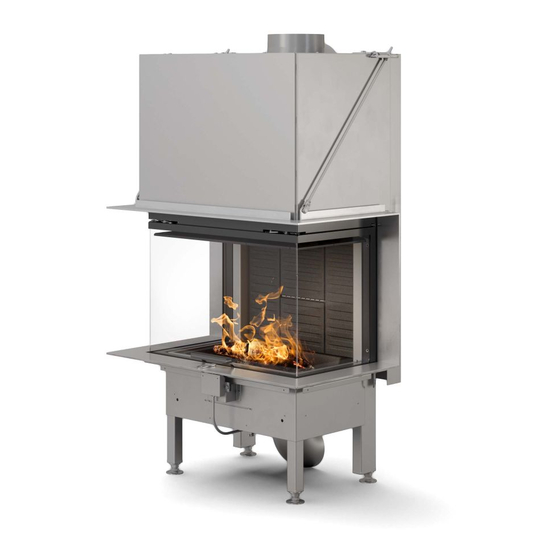
TECHNICAL DATA SPECIFICATIONS Danish Technological Institute ref.: 300-ELAB-2564-EN VISIO UNIQ, 3-SIDED MODEL Nominal output (kW) Min./max. output (kW) 7–11* Heating area (m Fireplace insert W x D x H (mm) 891 X 632 X 1525 Combustion chamber W x D x H (mm) 482 X 279 X 250** Min. -
Page 6: Dimensional Sketches
DIMENSIONAL SKETCHES 1525 1525 1525 1525 1525 1398 1398 1398 1398 1398 364,5 364,5 364,5 364,5 364,5 159 * 149 * 159 * 159 * 149 * 445 * 445 * 149 * 445 * 445 * 445 * 445 * 159 * 149 * 159 *... -
Page 7: Rating Plate
FR: BOIS Foyer à durèe de combustion limitèe, homologué pour cheminée à connexions multiples. Utiliser seulement les combustibles recommandés. Hergestellt für /Produced for: ATTIKA FEUER AG, Brunnmatt 16, CH-6330 Cham / RAIS A/S, Industrivej 20, DK-9900 Frederikshavn EN - 6... -
Page 8: Installation
INSTALLATION INSTALLATION The following section explains how to install the fireplace insert and includes informa- tion about packaging, placement distances, etc. PACKAGING AT DELIVERY Upon delivery, the fireplace insert is secured to a transport pallet using four transport safety fittings. The safety fittings are attached with screws which must be unscrewed. -
Page 9: Uk-Specific Instructions
UK-SPECIFIC INSTRUCTIONS Important! According to DEFRA rules, the installation of Visio Uniq in the UK requires the insertion of a mechanical stopper in the flue. Before Visio Uniq may be installed in a ‘smoke-controlled area’ of the UK, a stopper must be installed. -
Page 10: Norway-Specific Instructions
NORWAY-SPECIFIC INSTRUCTIONS Important! The installation of Visio Uniq in Norway pursuant to Norway’s open-plan office rules requires the insertion of a mechanical stopper in the flue. Before Visio Uniq may be installed in Norway, a stopper must be installed. This will pre- vent the flue from closing entirely. -
Page 11: Transport Safety Fittings
TRANSPORT SAFETY FITTINGS Important! For delivery, the door is locked in transit and it must be released before installation. This is done by removing the two transport screws in the counterweights on the back of the stove! EN - 10... -
Page 12: Reflective Insulation Panel
REFLECTIVE INSULATION PANEL For installation with a top outlet, a reflective insulation panel must be installed to cover the flue collar up to the insulated chimney pipe. The reflective insulation panel is included and is found screwed onto the back of fire- place insert. - Page 13 REFLECTIVE INSULATION PANEL Release the reflective insulation panel and turn it upside down (180°). Bend the two cut-out easy-bend flanges 90° (see photo below). Loosen the two labelled screws, one on each side. Place the two bottom holes on the reflective insulation panel over the two screws on the back of the stove.
-
Page 14: Choice Of Material For Installation
INSTALLATION CHOICE OF MATERIAL FOR INSTALLATION The material can be panels/brick with an insulation value greater than 0.03 m² x K/W. The insulation is defined as wall thickness (in metres) divided by the wall’s Lambda val- Consult your installation technician/chimney inspector. During testing, the fireplace insert is installed in a cabinet made of non-flammable 50 mm calcium silicate panels (Skamotec 225). - Page 15 EN - 14...
-
Page 16: Installation Dimensions
INSTALLATION DIMENSIONS INSTALLATION DIMENSIONS: Applies to installation into non-flammable panels. Minimum cavity dimensions (H x W x D): . 512 x 791 x 462 mm A fireplace insert must never be tightly inserted into a cavity, as steel expands when heated. -
Page 17: Placement Distances
SET-UP To guide the hot air out of the convec- tion grates, a non-flammable plate must be installed just over the grates. The insulated chimney must extend all the way down to the flue outlet adapter. EN - 16... - Page 18 SET-UP If the insulation value is complied with (greater than 0.03 m² x K/W), the cabinet may be installed against a flammable wall provided that the interior distance from stove to cabinet is at least 50 mm. MINIMUM DISTANCE Distance from door to furniture 1000 Distance from side glass to furniture Interior distance to cabinet...
- Page 19 INSTALLATION If the fireplace insert is installed so that the vertical built-in frame is flush against the wall, the first 100 mm of the wall must be made of non-combustible material such as 50 mm Skamotec 225 or brick. Combustible Not Combustible EN - 18...
-
Page 20: Heat Distributor
HEAT DISTRIBUTOR HEAT DISTRIBUTOR By installing a heat distributor unit above the fireplace insert, heat can be ‘transported’ to other rooms. 19 - EN... -
Page 21: External Air Connection
EXTERNAL AIR CONNECTION, AIRSYSTEM EXTERNAL AIR CONNECTION, AIRSYSTEM All RAIS/ATTIKA fireplace inserts can have an external air connection for combustion. We call this external air supply AirSystem. The system can be connected to the under- side of the fireplace insert. -
Page 22: Removing The Combustion Chamber Lining
REMOVING THE COMBUSTION CHAMBER LINING REMOVING THE COMBUSTION CHAMBER LINING The combustion chamber lining protects the body of the fireplace insert from the heat of the fire. The widely fluctuating temperatures can cause the combustion cham- ber lining to crack. This will not affect the functionality of the fireplace insert. The lin- ing does not need to be replaced until, after several years of use, it begins to crumble. -
Page 23: Cleaning The Flue
CLEANING THE FLUE CLEANING THE FLUE Remove the flue panel (see the section ‘Removing the combustion chamber lining’) A steel baffle is positioned between the two convection ducts above the flue panel. The steel baffle is held in place by two guide pins. Remove the steel baffle by pushing the front end up, disengaging it from the brackets and then tilting the baffle down between the ducts. -
Page 24: Cleaning The Door Glass
With rear outlet Cleaning the door glass Before the side glass can be opened for cleaning, the door must be placed in the bot- tom position. Then the upper locking pawl which is located above the door is released by turning it to the right on the right side and left on the left side. The door is lifted so that the lower locking pawl is just free of the bottom frame, and the locking pawl is released. -
Page 25: Cleaning The Combustion Chamber
Cleaning the combustion chamber Scrape/shovel the ash into the grate in the centre of the fireplace insert. The ash drawer underneath the grate can be removed and emptied in a non-combustible container until it has cooled off. Ash can be disposed of as ordinary household waste. REMEMBER! •... -
Page 26: Converting To Self-Closing Door
Convert to self-closing door before building in the insert. Convert the door to self-closure by removing some of the door’s counterweights. There are counterweights on both sides. 1. Remove the transport safety fittings and retainer screws for the counterweight cover Transport safety fitting. - Page 27 Convert to self-closing door after building in the insert. Convert the door to self-closure by removing some of the door’s counterweights. There are counterweights on both sides. 1. Remove the side Skamol panel. 2. Remove the access panel. Access panel. 3.
-
Page 28: Declaration Of Performance
DECLARATION OF PERFORMANCE DECLARATION OF PERFORMANCE 27 - EN... -
Page 29: Test Certificate
Ud d r a g a f r a p p o r t n r . 3 0 0 - ELA B- 2 5 6 4 - EN o g 3 0 0 - ELA B- 2 5 6 4 - N S Em n e : Rais Visio Uniq - 3 sider Re k v i r e n t :... - Page 30 29 - EN...
- Page 31 EN - 30...
- Page 32 RAIS A/S ATTIKA FEUER AG Industrivej 20 Brunnmatt 16 DK-9900 Frederikshavn CH-6330 Cham Denmark Switzerland www.rais.dk www.attika.ch...
Need help?
Do you have a question about the attika VISIO UNIQ and is the answer not in the manual?
Questions and answers