Advertisement
Quick Links
Advertisement

Related Manuals for JETWAY G03-JC330MU10QIG-F


Summary of Contents for JETWAY G03-JC330MU10QIG-F
- Page 1 Quick Installation Guide NO: G03-JC330MU10QIG-F Rev: 2.0 Release Date: 2022-05-05...
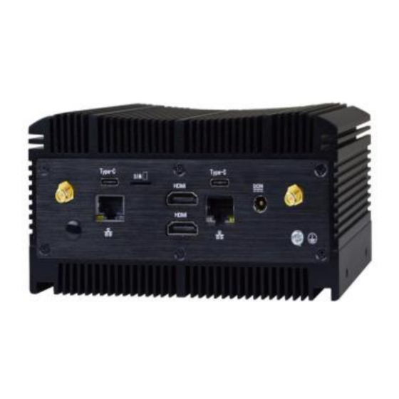
- Page 2 I/O Outlets: Front: Rear:...
- Page 3 Dimension and Outlines:...
- Page 4 I. To Dissemble the Chassis 1. Put the system upon a stable platform with this side up, as the photo shows. 2. Locate the screws at the spots marked on this cover and unscrew them one by one to open the chassis. 3.
- Page 5 Thermal Thermal Conductive Bar Conductive Bar 4. The internal structural view of the system for further installation. * Note: Please replace the thermal conductive bar if there is any damage found. II. To Install SO-DIMM to the Board 1. Locate the SO-DIMM slot on the board. side of the compatible SO-DIMM into the slot at a 30 degree angle.
- Page 6 3. Press down to secure the SO-DIMM to the slot. The eject tabs will lock automatically if installing direction is correct. III. To Install M.2 E-key (2230) PCIe Card 1. Locate the M.2 E-Key, Type-2230 slot on the board. 2. Remove the marked screw with a screwdriver.
- Page 7 3. Insert the gold-figure side of compatible M.2 PCIe card into the slot until the golden finger side fully emerged into the slot. 4. Install the screw back to the original spot. 5. Locate the reserved antenna holes on the rear panel. Remove the dust-proof plugs on the marked spots from the panel to install the antenna.
- Page 8 And then 6. Push this antenna head into antenna hole of the rear panel from the backside of the panel. push the washer①through the antenna head. Lock the antenna head to the front side of the rear panel with the hexagonal screw nut②and tighten it up. 7.
- Page 9 9. Repeat step 6 to 8, to finish installation of the other antenna. IV. To Install M.2 M-key (2242/2280) PCIe Card 1. Locate the M.2 M-Key, type-2242/2280 slot on the board.
- Page 10 2. Remove the marked screw with a screwdriver. 3. Insert the gold-figure side of compatible M.2 PCIe 2280 card into the slot until the golden finger side fully emerged into the slot. 4. Install the screw back to the original spot.
- Page 11 *Note: the screw post and nut fixed at location MH4 by default for 8cm type-2280 card installation. If you wish to install type-2242 card, please remove corresponding screw on the screw bolt fixed at location MH1 before installing 4.2 cm card to the slot. The other steps are the same. V.
- Page 12 3. Insert the gold-figure side of compatible M.2 PCIe 3042 card into the slot until the golden finger side fully emerged into the slot. 4. Install the screw back to the original spot. *Note: the screw post and nut fixed at location MH2 by default for 4.2cm type-3042 card installation. If you wish to install type-3052 card, please remove corresponding screw post under the screw as well and lock the screw post into location MH3 before installing 5.2 cm card to the slot.
- Page 13 VI. To Attach Thermal Conductive Pads 1. Find the 4 pieces of thermal conductive pads (HCSHBFFHS1-1F*4 PCS; 30*14*9mm) in the accessories package and tear off the protective films from both sides of each thermal pad. 2. Stack 2 PCS of thermal conductive pads together upon M.2 M-key & M.2 B-key slots, as shown in the photo above.
- Page 14 4. After completion, please tighten up the four screws on the bottom cover, one screw on the front and the other on the rear IO panels to reassemble the chassis.
Need help?
Do you have a question about the G03-JC330MU10QIG-F and is the answer not in the manual?
Questions and answers