
Related Manuals for JETWAY HBFMF833W Series


Summary of Contents for JETWAY HBFMF833W Series
- Page 1 User’s Manual NO. G03-FMF833QIG-F Manual Revision: 1.0 Release Date:December 17, 2018...
-
Page 2: Table Of Contents
TABLE OF CONTENT Safety Precautions ......................ii User’s Notice ........................iii Item Checklist ........................iii Environmental Protection Announcement ............... iii Chapter 1 Introduction ...................... 1 1-1 General Descriptions .................... 1 1-2 Specifications ......................1 1-3 Product Diagram ....................2 1-4 I/O Outlets......................3 1-5 Connector Pin Definition .................. -
Page 3: Safety Precautions
Safety Precautions Operate the product according to the correct installation steps and with great care to make sure safety and comfort using experience. Please refer to the following safety instruction guide to avoid danger of electric shock or fire. Abide by the previous safety instruction guide to use and maintain the product and the hard disk to make sure of safe operating environment. -
Page 4: User's Notice
User’s Notice Copyright of this manual belongs to the manufacturer. No part of this manual, including the products and software described in it may be reproduced, transmitted or translated into any language in any form or by any means without written permission of the manufacturer. This manual contains all information required for the utilization of this product to meet the user’s requirements. -
Page 5: Chapter 1 Introduction
Chapter 1 Introduction 1-1 General Descriptions Thank you for purchasing HBFMF833W Series, a Fanless Embedded Box PC developed, designed and manufactured under leading technical power and consistent dedication to fine workmanship. The system has the following features besides other basic functions: ®... -
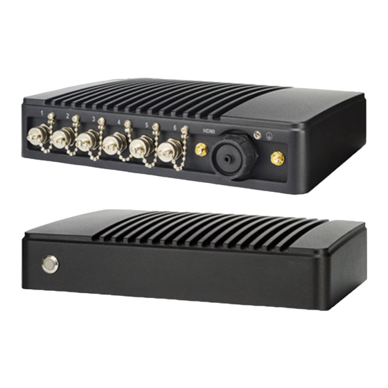
Page 6: Product Diagram
IP69K Waterproof Operating Temperature: -20 ~ 60°C (under the condition of using Environment MSATA) Operating Temperature: -20 ~ 70°C (under the condition of using 2.5” SSD) The test environment is closed and windless *Note: Storage Temperature: -10 ~ 70 °C Humidity : 90% , non-condensing 250 (W) x 171 (D) x 54 (H) mm Dimensions... -
Page 7: I/O Outlets
1-4 I/O Outlets HBFM833W-7X-2L-B: COM1: USB 3.0 DC-IN USB 2.0 RJ-45 LAN RS232/422/485 HBFM833W-7X-2C-B: COM1: RS232/422/485 COM2: DC-IN RJ-45 LAN USB 2.0 USB 2.0 RS232... -
Page 8: Connector Pin Definition
1-5 Connector Pin Definition (1) Connector Function Icon Name Function Power Button Press to turn on/off the system. HDMI To connect display device that support HDMI HDMI specification. DC-in Power For user to connect compatible power adapter to Connector provide power supply for the system. USB2.0 To connect USB keyboard, mouse or other devices USB 2.0 Port... - Page 9 (2) I/O Connectors Pin Definition DC: DC-in Power Connector The pin assignment for DC-in power connector is listed as follows: Pin NO. Definition DC +9~24V DC +9~24V LAN: RJ-45 Ethernet Connector The pin assignment for RJ-45 Ethernet LAN connectors are listed as follows: Pin NO.
- Page 10 USB3.0: USB 3.0 Port Connector The pin assignment for USB 3.0 port connectors are listed as follows: Pin NO. Definition USB3_RX- USB3_RX+ USB3_TX- USB3_TX- COM1: RS232/422/485 COM Port Connector The pin assignment for RS-232/ 422/ 485 is listed as follows: Pin NO.
-
Page 11: Chapter 2 Hardware And Installation
Chapter 2 Hardware and Installation 2-1 Dimension and Outlines * Measure Unit: mm. -
Page 12: To Open The Chassis
2-2 To Open the Chassis Use a screwdriver to unscrew the screws on the back cover that lock the chassis. Remove them and put the cover aside to open the chassis. Place the system upon a flat operation Lift up the cover to open the chassis. platform with side upwards. -
Page 13: Jumper Settings
2-3 Jumper Settings Jumper is a small component consisting of jumper clip and jumper pins. Install jumper clip on 2 jumper pins to close the pins. And remove jumper clip from 2 jumper pins to open the pins. Diagram 2-1 illustrates how to set up a jumper. JBAT JPCOM1 JPCOM2... - Page 14 AT_COPEN (4-pin): AT Mode & Case Open Detection Select Pin(1-2): AT Mode Select Pin(3-4):Case Open Detection Select Pin 1&2 of AT_COPEN Pin 3&4 of AT_COPEN → AT Mode Select → Case Open Detection Pin1 1-2 Open: ATX Mode Selected(Default); Pin1 Pin1 1-2 Closed: AT Mode Selected.
- Page 15 JPCOM1 (4-pin): COM1 Port Pin9 Function Select JPCOM2 (4-pin): COM2 Port Pin9 Function Select JPCOM3 (4-pin): COM3 Port Pin9 Function Select 2-4 Closed: 3-4 Closed: 6-4 Closed: Pin9 = 5V; Pin9=RING(Default); Pin9 = 12V. JPCOM4 (4-pin): COM4 Port Pin9 Function Select 5 3 1 5 3 1 6 4 2...
-
Page 16: Hardware Installation
2-4 Hardware Installation Remove the screws that lock the back cover to the system from the back side before hardware installation procedures (refer to 2-2). 2-4-1 To Install SO-DIMM 1. Locate the SO-DIMM memory slots on 2. See to it that the notch of the module fit the board. - Page 17 Insert the gold-figure side of the compatible Lock the card to the board by tightening card into the slot and press down. up the screw to the marked spot. Locate the antenna slots on the card. Press the metal hat on the end of the antenna string to the antenna slot on the card as shown (If you install two antenna, press the left metal hat of the...
-
Page 18: To Install Msata Card
2-4-3 To Install MSATA Card Locate the full-size Mini-PCIE/MSATA card Remove the marked screw and use it to slot on the board. lock MSATA card to the slot in later installation. Insert the gold-figure side of the compatible Lock the card to the board by tightening card into the slot and press down. - Page 19 Place compatible SATA HDD upon HDD Turn over the HDD tray and fix 2.5’’ HDD tray as showed above. Plug this side of upon HDD tray by tightening 4* screws the cable to SATA power-in connector marked in corresponding spots. and SATA connector of the hard disk.
-
Page 20: To Wall Mount The System
2-4-4 To Wall Mount the System Find a pair of racks for wall-mount Place the system upon a flat operation from the accessories package. The platform with side upwards. The screw holes in screw holes in the marked spots the marked spots are reserved for wall mount should be aligned to the screw holes rack installation. -
Page 21: Chapter 3 Introducing Bios
Chapter 3 Introducing BIOS Notice! The BIOS options in this manual are for reference only. Different configurations may lead to difference in BIOS screen and BIOS screens in manuals are usually the first BIOS version when the board is released and may be different from your purchased motherboard. Users are welcome to download the latest BIOS version form our official website. -
Page 22: Bios Menu Screen
BIOS Menu Screen The following diagram show a general BIOS menu screen: Menu Bar General Help Items Menu Items Current Setting Value Function Keys BIOS Menu Screen Function Keys In the above BIOS Setup main menu of, you can see several options. We will explain these options step by step in the following pages of this chapter, but let us first see a short description of the function keys you may use here: l Press¨... -
Page 23: Menu Bars
Press [F1] to pop up a small help window that describes the appropriate keys to use and the possible selections for the highlighted item. To exit the Help Window, press <Esc>. 3-5 Menu Bars There are six menu bars on top of BIOS screen: Main To change system basic configuration Advanced... -
Page 24: Advanced Menu
3-7 Advanced Menu ► CPU Configuration Press [Enter] to view current CPU configuration and make settings for the following sub-items: Hyper-Threading The optional settings: [Disabled]; [Enabled]. [Enabled]: for Windows and Linux(OS optimized Hyper-Threading Technology). [Disabled]: for other OS (OS not optimized for Hyper-Threading Technology). Intel Virtualization Technology The optional settings: [Enabled];... - Page 25 [Auto]: Initializes to deepest available Package C State Limit. ► SATA Configuration Press [Enter] to make settings for the following sub-items: SATA Controller(s) The optional settings: [Disabled]; [Enabled]. When set as [Enabled], user can make further settings in the following items: SATA Mode Selection The optional setting is: [AHCI].
- Page 26 The optional settings: [Disabled]; [Enabled]. MEBx Debug Message Output Use this item to enable MEBx debug message output. The optional settings: [Disabled]; [Enabled]. Un-Configure ME Use this item to unconfigure ME with resetting MEBx password to default. The optional settings: [Disabled]; [Enabled]. Use this item to enable or disable Alert Standard Format support.
- Page 27 Wake-up System with Dynamic Time Use this item to enable or disable system wake on alarm event. System will wake on the current time + Increase minutes. The optional settings: [Disabled]; [Enabled]. When set as [Enabled], system will wake on the current time + increased minute(s).
- Page 28 Change Settings Use this item to select an optimal setting for super IO device. Changing setting may conflict with system resources. Serial Port FIF0 Mode The optional settings are: [16-Byte FIF0]; [32-Byte FIF0]; [64-Byte FIF0]; [128-Byte FIF0]. WatchDog Reset Timer Use this item to enable or disable WDT reset function.
- Page 29 C/185 F]; [90 C/194 4 Serial Port Console Redirection COM1 Console Redirection The optional settings are: [Disabled]; [Enabled]. When set as [Enabled], the following sub-items shall appear: 4 Console Redirection Settings The settings specify how the host computer and the remote computer (which the user is using) will exchange data.
- Page 30 Resolution 100x31 Use this item to enable or disable extended terminal resolution. The optional settings: [Disabled]; [Enabled]. Legacy OS Redirection Resolution Use this item to enable or disable extended terminal resolution. The optional settings: [80x24]; [80x25]. Putty KeyPad Use this item to select the number of Rows and Columns supported redirection on Legacy OS.
- Page 31 *This item may or may not show up, depending on different configuration. Parity The default setting is: [None]. *This item may or may not show up, depending on different configuration. Stop Bits The default setting is: [1]. *This item may or may not show up, depending on different configuration. ►...
-
Page 32: Chipset Menu
USB Configuration Legacy USB Support The optional settings are: [Enabled]; [Disabled]; [Auto]. [Enabled]: To enable legacy USB support. [Disabled]: to keep USB devices available only for EFI specification, [Auto]: To disable legacy support if no USB devices are connected. XHCI Hand-off This is a workaround for OSes without XHCI hand-off support. - Page 33 ► System Agent (SA) Configuration Press [Enter] to make settings for the following sub-items: VT-d The optional settings are: [Enabled]; [Disabled]. This item might not be available depending on configuration. ► Graphics Configuration Press [Enter] to make further settings for Graphics Configuration. Graphics Configuration GTT Size Use this item to select the GTT size.
- Page 34 24bit Single]; [1366 x 768 18bit Single]; [1366 x 768 24bit Single]; [1440 x 900 18bit Dual]; ; [1440 x 900 24bit Dual]; [1280 x 1024 24bit Dual]; [1680 x 1050 24bit Dual]; [1920 x 1080 24bit Dual]. LVDS FW Write Protect Use this item to enable or disable LVDS FW Update/Protect.
-
Page 35: Security Menu
3-9 Security Menu Security menu allow users to change administrator password and user password settings. Administrator Password Press [Enter] to create new administrator password. Press again to confirm the new administrator password. User Password Press [Enter] to create new user password. Press again to confirm the new user password. -
Page 36: Save & Exit Menu
Use this item to select keyboard numlock state. The optional settings are: [On]; [Off]. Quiet Boot The optional settings are: [Disabled]; [Enabled]. Boot Option Priorities Boot Option #1/ Boot Option #2… Use this item to decide system boot order from available options. UEFI Boot The optional settings are: [Disabled];...
Need help?
Do you have a question about the HBFMF833W Series and is the answer not in the manual?
Questions and answers