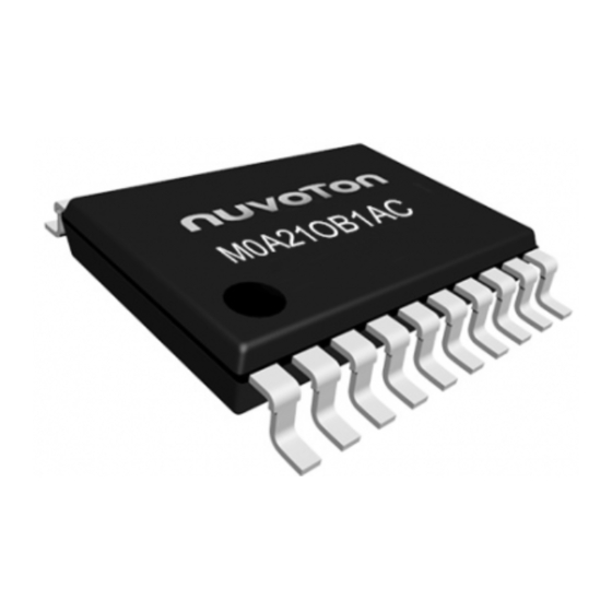
Summary of Contents for Nuvoton NuMicro M0A21 Series
Page 1
M0A21/M0A23 Series Technical Reference Manual The information described in this document is the exclusive intellectual property of Nuvoton Technology Corporation and shall not be reproduced without permission from Nuvoton. ® Nuvoton is providing this document only for reference purposes of NuMicro microcontroller and microprocessor based system design.
M0A21/M0A23 Series TABLE OF CONTENTS 1 GENERAL DESCRIPTION ................17 2 FEATURES ....................18 3 PARTS INFORMATION ................. 26 3.1 Package Type ......................26 3.2 NuMicro M0A21/M0A23 Series Selection Guide ..........27 ® 3.2.1 NuMicro M0A21 Series ....................27 ® 3.2.2 NuMicro M0A23 Series ....................
Page 13
M0A21/M0A23 Series Figure 6.15-19 GC Mode with 7-bit Address ................582 Figure 6.15-20 Setup Time Wrong Adjustment ................584 Figure 6.15-21 Hold Time Wrong Adjustment ................584 Figure 6.15-22 I C Time-out Count Block Diagram ..............585 Figure 6.15-23 EEPROM Random Read ..................586 Figure 6.15-24 Protocol of EEPROM Random Read ..............
Page 14
M0A21/M0A23 Series Figure 6.21-1 Analog Comparator Block Diagram ............... 722 Figure 6.21-2 Comparator Hysteresis Function of ACMP0 ............723 Figure 6.21-3 Window Latch Mode ....................724 Figure 6.21-4 Filter Function Example ..................724 Figure 6.21-5 Comparator Controller Interrupt ................725 Figure 6.21-6 Comparator Reference Voltage Block Diagram ............
Page 15
M0A21/M0A23 Series List of Tables ® Table 1-1 NuMicro M0A21/M0A23 Series Key Features Table ........... 17 Table 6.2-1 Reset Value of Registers ..................103 Table 6.2-2 Power Mode Table ....................108 Table 6.2-3 Power Mode Difference Table .................. 108 Table 6.2-4 Power Mode Difference Table .................. 108 Table 6.2-5 Clocks in Power Modes ....................
Page 16
M0A21/M0A23 Series Table 6.12-2 Output Signals for Different Protocols ..............487 Table 6.12-3 Data Transfer Events and Interrupt Handling ............494 Table 6.12-4 Protocol-specific Events and Interrupt Handling ............. 494 Table 6.13-1 Input Signals for UART Protocol ................499 Table 6.13-2 Output Signals for Different Protocol ..............499 Table 6.14-1 Serial Bus Clock Configuration ................
M0A21/M0A23 Series GENERAL DESCRIPTION ® ® ® The NuMicro M0A21/M0A23 series is a 32-bit microcontroller based on Arm Cortex -M0 core. It provides compact package with highly flexible digital pin function assignment, rich analog peripherals, - 40°C to 125°C operating temperature, 2.4V ~ 5.5V operating voltage, CAN 2.0B and LIN interface for ®...
32-bit quotient and 32-bit remainder outputs (16-bit remainder with sign extends to 32-bit) 6 HCLK clocks taken for one cycle calculation Memories Nuvoton ISP (In-System-Programming) tool for firmware upgrade via UART Boot Loader ISP/IAP libraries Up to 32 KB application ROM (APROM) ...
Page 19
M0A21/M0A23 Series Data Flash with configurable memory size 2-wired ICP Flash updating through SWD interface 32-bit and multi-word Flash programming function Up to 4 KB embedded SRAM SRAM Supports byte-, half-word- and word-access Supports PDMA mode ...
Page 20
M0A21/M0A23 Series ±0.25% accuracy that can optionally be used as a system clock 38.4 kHz Low-speed Internal RC oscillator (LIRC) for watchdog timer and wakeup operation Timers Four sets of 32-bit timers with 24-bit up counter and one 8-bit pre-scale counter from independent clock source ...
Page 21
M0A21/M0A23 Series Interrupt or reset selectable on watchdog time-out Supports selectable WDT reset delay period, including 1026, 130, 18 or 3 WDT_CLK reset delay period. Supports to force WDT enabled after chip powered on or reset by setting CWDTEN[2:0] in Config0 register. ...
Page 22
M0A21/M0A23 Series Conversion result can be compared with specified value and user can select whether to generate an interrupt when conversion result matches the compare register setting. 4 internal channels band-gap voltage (VBG), temperature sensor (V ), internal reference voltage and DAC0 output TEMP ...
Page 23
M0A21/M0A23 Series Supports triggers for break events and cycle-by-cycle control for Supports window compare mode and window latch mode Communication Interfaces Supports up to 2 UARTs: UART0, UART1 UART baud rate clock from LXT (32.768 kHz) with 9600bps can work normally in power down mode even system clock is stopped ...
Page 24
M0A21/M0A23 Series Supports RS-485 mode Supports RS-485 9-bit mode Supports hardware or software enables to program nRTS pin to control RS-485 transmission direction Supports nCTS, incoming data, Received Data FIFO reached threshold and RS-485 Address Match (AAD mode) wake-up function ...
Page 25
M0A21/M0A23 Series Supports one data channel half-duplex transfer Full master and slave device capability 7-bit addressing mode (10-bit mode Not supported) Communication in standard mode (100 kbps) or in fast mode (up to 400 kbps) Multi-master bus ...
M0A21/M0A23 Series PARTS INFORMATION 3.1 Package Type SSOP20 TSSOP28 M0A21OB1AC M0A21EB1AC M0A21OC1AC M0A21EC1AC M0A23OC1AC M0A23EC1AC May 06, 2022 Page 26 of 746 Rev 1.02...
M0A21/M0A23 Series ® 3.2 NuMicro M0A21/M0A23 Series Selection Guide ® 3.2.1 NuMicro M0A21 Series Connectivity Part Number M0A21OB1AC 17-ch SSOP20 M0A21OC1AC 17-ch SSOP20 M0A21EB1AC 17-ch TSSOP28 M0A21EC1AC 17-ch TSSOP28 USCI*: supports UART, SPI or I ® 3.2.2 NuMicro M0A23 Series Connectivity Part Number M0A23OC1AC...
The pin configuaration information can be found in the M0A21/M0A23 Series Multi-function Summary Table section or by using NuTool - PinConfigure. The NuTool - PinConfigure contains all Nuvoton ® NuMicro Family chip series with all part number, and helps configure GPIO multi-function pins correctly and handily.
M0A21/M0A23 Series 4.2 Pin Description Different part number with same package might have different functions. Please refer to the selection guide in section 3.2. 4.2.1 M0A21/M0A23 Series Pin Description Pin Name Type Description MFP0 Power supply for I/O ports and LDO source for internal PLL and digital circuit.
Page 45
M0A21/M0A23 Series Pin Name Type Description UART1_TXD MFP28 UART1 data transmitter output pin. UART1_RXD MFP29 UART1 data receiver input pin. ACMP0_WLAT MFP30 Analog comparator 0 window latch input pin PA.4 MFP0 General purpose digital I/O pin. ADC0_CH15 MFP1 ADC0 channel 15 analog input. UART0_nRTS MFP2 UART0 request to Send output pin.
Page 46
M0A21/M0A23 Series Pin Name Type Description PA.3 MFP0 General purpose digital I/O pin. nRESET MFP2 External reset input: active LOW, with an internal pull-up. Set this pin low reset to initial state. Note: It is recommended to use 10 kΩ pull-up resistor and 10 uF capacitor on nRESET pin.
Page 47
M0A21/M0A23 Series Pin Name Type Description UART0_TXD MFP8 UART0 data transmitter output pin. UART0_RXD MFP9 UART0 data receiver input pin. USCI0_CLK MFP10 USCI0 clock pin. USCI0_DAT0 MFP11 USCI0 data 0 pin. USCI0_DAT1 MFP12 USCI0 data 1 pin. USCI0_CTL0 MFP13 USCI0 control 0 pin. USCI0_CTL1 MFP14 USCI0 control 1 pin.
Page 48
M0A21/M0A23 Series Pin Name Type Description USCI0_DAT0 MFP11 USCI0 data 0 pin. USCI0_DAT1 MFP12 USCI0 data 1 pin. USCI0_CTL0 MFP13 USCI0 control 0 pin. USCI1_CTL1 MFP14 USCI1 control 1 pin. USCI1_CLK MFP15 USCI1 clock pin. USCI1_DAT0 MFP16 USCI1 data 0 pin. USCI1_DAT1 MFP17 USCI1 data 1 pin.
Page 49
M0A21/M0A23 Series Pin Name Type Description USCI0_DAT1 MFP12 USCI0 data 1 pin. USCI0_CTL0 MFP13 USCI0 control 0 pin. USCI0_CTL1 MFP14 USCI0 control 1 pin. USCI1_CLK MFP15 USCI1 clock pin. USCI1_DAT0 MFP16 USCI1 data 0 pin. USCI1_DAT1 MFP17 USCI1 data 1 pin. USCI1_CTL0 MFP18 USCI1 control 0 pin.
Page 50
M0A21/M0A23 Series Pin Name Type Description UART1_nCTS MFP6 UART1 clear to Send input pin. 11 PD.3 MFP0 General purpose digital I/O pin. PWM0_CH1 MFP2 PWM0 channel 1 output/capture input. CAN0_RXD MFP3 CAN0 bus receiver input. USCI1_CTL0 MFP4 USCI1 control 0 pin. MFP5 Timer3 event counter input/toggle output pin.
Page 51
M0A21/M0A23 Series Pin Name Type Description TM2_EXT MFP27 Timer2 external capture input/toggle output pin. UART1_TXD MFP28 UART1 data transmitter output pin. UART1_RXD MFP29 UART1 data receiver input pin. INT4 MFP30 External interrupt 4 input pin. 13 PC.7 MFP0 General purpose digital I/O pin. ADC0_CH10 MFP1 ADC0 channel 10 analog input.
Page 52
M0A21/M0A23 Series Pin Name Type Description INT5 MFP30 External interrupt 5 input pin. 14 PB.7 MFP0 General purpose digital I/O pin. ADC0_CH9 MFP1 ADC0 channel 9 analog input. UART0_nRTS MFP2 UART0 request to Send output pin. UART0_nCTS MFP3 UART0 clear to Send input pin. CLKO MFP4 Clock Out...
Page 53
M0A21/M0A23 Series Pin Name Type Description UART0_nRTS MFP2 UART0 request to Send output pin. UART0_nCTS MFP3 UART0 clear to Send input pin. CLKO MFP4 Clock Out PWM0_CH1 MFP5 PWM0 channel 1 output/capture input. PWM0_CH3 MFP6 PWM0 channel 3 output/capture input. PWM0_CH5 MFP7 PWM0 channel 5 output/capture input.
Page 54
M0A21/M0A23 Series Pin Name Type Description PWM0_CH0 MFP5 PWM0 channel 0 output/capture input. PWM0_CH2 MFP6 PWM0 channel 2 output/capture input. PWM0_CH4 MFP7 PWM0 channel 4 output/capture input. UART0_TXD MFP8 UART0 data transmitter output pin. UART0_RXD MFP9 UART0 data receiver input pin. USCI0_CLK MFP10 USCI0 clock pin.
Page 55
M0A21/M0A23 Series Pin Name Type Description USCI0_DAT0 MFP4 USCI0 data 0 pin. MFP5 Timer1 event counter input/toggle output pin. 19 PD.6 MFP0 General purpose digital I/O pin. PWM0_CH2 MFP2 PWM0 channel 2 output/capture input. CAN0_TXD MFP3 CAN0 bus transmitter output. USCI0_DAT1 MFP4 USCI0 data 1 pin.
Page 56
M0A21/M0A23 Series Pin Name Type Description CAN0_RXD MFP20 CAN0 bus receiver input. ACMP0_O MFP21 Analog comparator 0 output pin. ACMP1_O MFP22 Analog comparator 1 output pin. ADC0_ST MFP23 ADC0 external trigger input pin. MFP24 Timer1 event counter input/toggle output pin. MFP25 Timer3 event counter input/toggle output pin.
M0A21/M0A23 Series Pin Name Type Description TM1_EXT MFP26 Timer1 external capture input/toggle output pin. TM3_EXT MFP27 Timer3 external capture input/toggle output pin. UART1_TXD MFP28 UART1 data transmitter output pin. UART1_RXD MFP29 UART1 data receiver input pin. PWM0_BRAKE1 MFP30 PWM0 Brake 1 input pin. 28 V MFP0 Ground pin for digital circuit.
Page 63
M0A21/M0A23 Series Group Pin Name GPIO Type Description ACMP0_WLAT PA.5 MFP30 Analog comparator 0 window latch input pin ACMP0_WLAT PB.7 MFP30 Analog comparator 0 window latch input pin ACMP1_N0 PA.1 MFP1 Analog comparator 1 negative input 0 pin. ACMP1_N1 PC.1 MFP1 Analog comparator 1 negative input 1 pin.
Page 64
M0A21/M0A23 Series Group Pin Name GPIO Type Description ADC0_CH16 PA.5 MFP1 ADC0 channel 16 analog input. ADC0_CH2 PA.2 MFP1 ADC0 channel 2 analog input. ADC0_CH3 PC.0 MFP1 ADC0 channel 3 analog input. ADC0_CH4 PC.1 MFP1 ADC0 channel 4 analog input. ADC0_CH5 PC.2 MFP1...
Page 65
M0A21/M0A23 Series Group Pin Name GPIO Type Description CAN0_RXD PC.6 MFP20 CAN0 bus receiver input. CAN0_RXD PC.7 MFP20 CAN0 bus receiver input. CAN0_RXD PB.7 MFP20 CAN0 bus receiver input. CAN0_RXD PB.6 MFP20 CAN0 bus receiver input. CAN0_RXD PB.5 MFP20 CAN0 bus receiver input. CAN0_RXD PD.7 MFP3...
Page 66
M0A21/M0A23 Series Group Pin Name GPIO Type Description CLKO PC.5 MFP4 Clock Out CLKO PC.4 MFP4 Clock Out CLKO PC.3 MFP4 Clock Out CLKO PC.6 MFP4 Clock Out CLKO PC.7 MFP4 Clock Out CLKO PB.7 MFP4 Clock Out CLKO PB.6 MFP4 Clock Out CLKO...
M0A21/M0A23 Series 4.2.3 M0A21/M0A23 Series Multi-function Summary Table Sorted by GPIO Pin Name Type Description PA.0 MFP0 General purpose digital I/O pin. ADC0_CH0 MFP1 ADC0 channel 0 analog input. DAC0_OUT MFP1 DAC0 channel analog output. ACMP0_P0 MFP1 Analog comparator 0 positive input 0 pin. ICE_DAT MFP2 Serial wired debugger data pin.
Page 81
M0A21/M0A23 Series Pin Name Type Description PWM0_BRAKE1 MFP30 PWM0 Brake 1 input pin. PA.1 MFP0 General purpose digital I/O pin. ADC0_CH1 MFP1 ADC0 channel 1 analog input. ACMP0_N0 MFP1 Analog comparator 0 negative input 0 pin. ACMP1_N0 MFP1 Analog comparator 1 negative input 0 pin. MFP1 ADC reference voltage input.
Page 82
M0A21/M0A23 Series Pin Name Type Description UART1_TXD MFP28 UART1 data transmitter output pin. UART1_RXD MFP29 UART1 data receiver input pin. PWM0_BRAKE0 MFP30 PWM0 Brake 0 input pin. PA.2 MFP0 General purpose digital I/O pin. ADC0_CH2 MFP1 ADC0 channel 2 analog input. UART0_nRTS MFP2 UART0 request to Send output pin.
Page 83
M0A21/M0A23 Series Pin Name Type Description PA.3 MFP0 General purpose digital I/O pin. nRESET MFP2 External reset input: active LOW, with an internal pull-up. Set this pin low reset to initial state. Note: It is recommended to use 10 kΩ pull-up resistor and 10 uF capacitor on nRESET pin.
Page 84
M0A21/M0A23 Series Pin Name Type Description UART0_RXD MFP9 UART0 data receiver input pin. USCI0_CLK MFP10 USCI0 clock pin. USCI0_DAT0 MFP11 USCI0 data 0 pin. USCI0_DAT1 MFP12 USCI0 data 1 pin. USCI0_CTL0 MFP13 USCI0 control 0 pin. USCI1_CTL1 MFP14 USCI1 control 1 pin. USCI1_CLK MFP15 USCI1 clock pin.
Page 85
M0A21/M0A23 Series Pin Name Type Description USCI0_DAT1 MFP12 USCI0 data 1 pin. USCI0_CTL0 MFP13 USCI0 control 0 pin. USCI0_CTL1 MFP14 USCI0 control 1 pin. USCI1_CLK MFP15 USCI1 clock pin. USCI1_DAT0 MFP16 USCI1 data 0 pin. USCI1_DAT1 MFP17 USCI1 data 1 pin. USCI1_CTL0 MFP18 USCI1 control 0 pin.
Page 86
M0A21/M0A23 Series Pin Name Type Description USCI1_CLK MFP15 USCI1 clock pin. USCI1_DAT0 MFP16 USCI1 data 0 pin. USCI1_DAT1 MFP17 USCI1 data 1 pin. USCI1_CTL0 MFP18 USCI1 control 0 pin. CAN0_TXD MFP19 CAN0 bus transmitter output. CAN0_RXD MFP20 CAN0 bus receiver input. ACMP0_O MFP21 Analog comparator 0 output pin.
Page 87
M0A21/M0A23 Series Pin Name Type Description USCI1_CTL0 MFP18 USCI1 control 0 pin. CAN0_TXD MFP19 CAN0 bus transmitter output. CAN0_RXD MFP20 CAN0 bus receiver input. ACMP0_O MFP21 Analog comparator 0 output pin. ACMP1_O MFP22 Analog comparator 1 output pin. ADC0_ST MFP23 ADC0 external trigger input pin.
M0A21/M0A23 Series FUNCTIONAL DESCRIPTION ® ® 6.1 Arm Cortex -M0 Core ® The Cortex -M0 core is a configurable, multistage, 32-bit RISC processor, which has an AMBA AHB- Lite interface and includes an NVIC component. It also has optional hardware debug functionality. The ®...
Page 100
M0A21/M0A23 Series Dedicated Non-maskable Interrupt (NMI) input – Supports for both level-sensitive and pulse-sensitive interrupt lines – Supports Wake-up Interrupt Controller (WIC) and, providing Ultra-low Power Sleep – mode Debug support: Four hardware breakpoints – Two watchpoints – Program Counter Sampling Register (PCSR) for non-intrusive code profiling –...
M0A21/M0A23 Series 6.2 System Manager 6.2.1 Overview System management includes the following sections: System Reset System Power Distribution SRAM Memory Orginization System Timer (SysTick) Nested Vectored Interrupt Controller (NVIC) System Control register 6.2.2 System Reset The system reset can be issued by one of the events listed below.
M0A21/M0A23 Series HCLKSEL Reload Reload Reload Reload Reload Reload Reload Reload from from from from from from from from (CLK_CLKSEL0[2:0]) CONFIG0 CONFIG0 CONFIG0 CONFIG0 CONFIG0 CONFIG0 CONFIG0 CONFIG0 WDTSEL (CLK_CLKSEL1[1:0]) HXTSTB (CLK_STATUS[0]) LXTSTB (CLK_STATUS[1]) HIRCSTB (CLK_STATUS[4]) CLKSFAIL (CLK_STATUS[7]) RSTEN Reload Reload Reload Reload...
M0A21/M0A23 Series nRESET Reset The nRESET reset means to generate a reset signal by pulling low nRESET pin, which is an asynchronous reset input pin and can be used to reset system at any time. When the nRESET voltage is lower than 0.2 V and the state keeps longer than 32 us (glitch filter), chip will be reset.
M0A21/M0A23 Series 2.2V Power-on Reset Figure 6.2-4 Power-on Reset (POR) Waveform Low Voltage Reset (LVR) If the Low Voltage Reset function is enabled by setting the Low Voltage Reset Enable Bit LVREN (SYS_BODCTL[7]) to 1, after 200us delay, LVR detection circuit will be stable and the LVR function will be active.
M0A21/M0A23 Series (SYS_BODCTL[10:8]), chip will be reset. The BOD reset will control the chip in reset state until the AV voltage rises above V and the state keeps longer than De-glitch time set by BODDGSEL. The default value of BODEN, BODVL and BODRSTEN (SYS_BODCTL[3]) is set by Flash controller user configuration register CBODEN...
M0A21/M0A23 Series The CHIP Reset is same with Power-on Reset. The CPU and all peripherals are reset and BS(FMC_ISPCTL[1]) bit is automatically reloaded from CONFIG0 setting. User can set the CHIPRST(SYS_IPRST0[0]) to 1 to assert the CHIP Reset signal. The MCU Reset is similar with CHIP Reset. The difference is that BS(FMC_ISPCTL[1]) will not be reloaded from CONFIG0 setting and keep its original software setting for booting from APROM or LDROM.
M0A21/M0A23 Series Idle mode CPU enter Sleep mode Only CPU clock is disabled. Power-down mode CPU enters Power-down Most clocks are disabled except LIRC/LXT, and only mode WDT/Timer/UART peripheral clocks still enable if their clock sources are selected as LIRC/LXT. Table 6.2-2 Power Mode Table There are different power mode entry settings and leaving condition for each power mode.
M0A21/M0A23 Series System reset released Normal Mode CPU Clock ON HXT , HIRC , LXT , LIRC , HCLK , PCLK ON Flash ON CPU executes WFI Interrupts occur 1. SLEEPDEEP (SCS_SCR[2]) = 1 Wake-up events 2. PDEN (CLK_PWRCTL[7]) = 1 and occur PDWKIF (CLK_PWRCTL[6]) = 1 3.
M0A21/M0A23 Series Normal Mode Idle Mode Power-Down Mode HXT (4~24 MHz XTL) Halt HIRC48 (48 MHz OSC) Halt LXT (32768 Hz XTL) ON/OFF LIRC (38.4 kHz OSC) ON/OFF MLDO ULDO Halt Halt HCLK/PCLK Halt SRAM retention FLASH Halt GPIO Halt PDMA Halt TIMER...
M0A21/M0A23 Series nCTS wake-up After software writes 1 to clear CTSWKF (UARTx_WKSTS[0]). RX Data wake-up After software writes 1 to clear DATWKF (UARTx_WKSTS[1]). Received FIFO Threshold After software writes 1 to clear RFRTWKF (UARTx_WKSTS[2]). UART0/1 Wake-up RS-485 AAD Mode Wake-up After software writes 1 to clear RS485WKF (UARTx_WKSTS[3]). Received FIFO Threshold After software writes 1 to clear TOUTWKF (UARTx_WKSTS[4]).
M0A21/M0A23 Series 6.2.6 SRAM Memory Orginization The M0A21/M0A23 supports embedded SRAM with total 4 Kbytes size Supports total 4 Kbytes SRAM Supports byte / half word / word write Supports oversize response error Table 6.2-9 shows the SRAM organization of M0A21/M0A23. The address between 0x2000_1000 to 0x3FFF_FFFF is illegal memory space and chip will enter hardfault if CPU accesses these illegal memory addresses.
M0A21/M0A23 Series 6.2.7 Chip Bus Matrix The M0A21/M0A23 series supports Bus Matrix to manage the access arbitration between masters. The access arbitration use round-robin algorithm as the bus priority. PDMA ® Cortex FLASH SRAM APB0 APB1 (ctrl) ® Figure 6.2-10 NuMicro M0A21/M0A23 Bus Matrix Diagram 6.2.8 IRC Auto Trim...
M0A21/M0A23 Series 6.2.9 Register Lock Control Some of the system control registers need to be protected to avoid inadvertent write and disturb the chip operation. These system control registers are protected after the power-on reset till user to disable register protection. For user to program these protected registers, a register protection disable sequence needs to be followed by a special programming.
M0A21/M0A23 Series 6.2.12 Register Description Part Device Identification Number Register (SYS_PDID) Register Offset Description Reset Value SYS_PDID SYS_BA+0x00 Part Device Identification Number Register 0xXXXX_XXXX [1] Every part number has a unique default reset value. PDID PDID PDID PDID Bits Description Part Device Identification Number (Read Only) [31:0] PDID This register reflects device part number code.
Page 119
M0A21/M0A23 Series System Reset Status Register (SYS_RSTSTS) This register provides specific information for software to identify this chip’s reset source from last operation. Register Offset Description Reset Value SYS_RSTSTS SYS_BA+0x04 System Reset Status Register 0x0000_0043 Reserved Reserved Reserved CPULKRF CPURF Reserved SYSRF BODRF...
Page 120
M0A21/M0A23 Series Bits Description BOD Reset Flag The BOD reset flag is set by the “Reset Signal” from the Brown-Out Detector to indicate the previous reset source. BODRF 0 = No reset from BOD. 1 = The BOD had issued the reset signal to reset the system. Note: Write 1 to clear this bit to 0.
Page 121
M0A21/M0A23 Series Peripheral Reset Control Register 0 (SYS_IPRST0) Register Offset Description Reset Value Peripheral Reset Control Register 0 SYS_IPRST0 SYS_BA+0x08 0x0000_0000 Reserved Reserved Reserved CRCRST Reserved HDIV_RST Reserved PDMARST CPURST CHIPRST Bits Description [31:8] Reserved Reserved. CRC Calculation Controller Reset (Write Protect) Set this bit to 1 will generate a reset signal to the CRC calculation controller.
Page 122
M0A21/M0A23 Series Chip One-shot Reset (Write Protect) Setting this bit will reset the whole chip, including Processor core and all peripherals, and this bit will automatically return to 0 after the 2 clock cycles. The CHIPRST is same as the POR reset, all the chip controllers is reset and the chip setting from Flash are also reload.
Page 123
M0A21/M0A23 Series Peripheral Reset Control Register 1 (SYS_IPRST1) Setting these bits 1 will generate asynchronous reset signals to the corresponding module controller. Users need to set these bits to 0 to release corresponding module controller from reset state. Register Offset Description Reset Value SYS_IPRST1...
Page 125
M0A21/M0A23 Series Peripheral Reset Control Register 2 (SYS_IPRST2) Setting these bits to 1 will generate asynchronous reset signals to the corresponding module controller. Users need to set these bits to 0 to release corresponding module controller from reset state. Register Offset Description Reset Value...
Page 126
M0A21/M0A23 Series Brown-out Detector Control Register (SYS_BODCTL) Partial of the SYS_BODCTL control registers values are initiated by the Flash configuration and partial bits are write-protected bit. Register Offset Description Reset Value SYS_BODCTL SYS_BA+0x18 Brown-out Detector Control Register 0x00XX_038X Reserved Reserved BODVL Reserved LVRDGSEL...
Page 127
M0A21/M0A23 Series Bits Description Brown-out Detector Output De-glitch Time Select (Write Protect) 000 = BOD output is sampled by RC32K clock. 001 = 64 system clock (HCLK). 010 = 128 system clock (HCLK). 011 = 256 system clock (HCLK). [10:8] BODDGSEL 100 = 512 system clock (HCLK).
Page 128
M0A21/M0A23 Series Bits Description Brown-out Reset Enable Bit (Write Protect) The default value is set by Flash controller user configuration register CBORST(CONFIG0[20]) bit . 0 = Brown-out “INTERRUPT” function Enabled. 1 = Brown-out “RESET” function Enabled. Note 1: While the Brown-out Detector function is enabled (BODEN high) and BOD reset function is enabled BODRSTEN (BODRSTEN high), BOD will assert a signal to reset chip when the detected voltage is lower than the threshold (BODOUT high).
Page 129
M0A21/M0A23 Series Internal Voltage Source Control Register (SYS_IVSCTL) Register Offset Description Reset Value SYS_IVSCTL SYS_BA+0x1C Internal Voltage Source Control Register 0x0000_0000 Reserved Reserved Reserved Reserved VTEMPEN Bits Description [31:2] Reserved Reserved. Temperature Sensor Enable Bit This bit is used to enable/disable temperature sensor function. 0 = Temperature sensor function Disabled (default).
Page 130
M0A21/M0A23 Series Power-on Reset Controller Register (SYS_PORCTL) Register Offset Description Reset Value SYS_PORCTL SYS_BA+0x24 Power-On-reset Controller Register 0x0000_0000 Reserved Reserved POROFF POROFF Bits Description [31:16] Reserved Reserved. Power-on Reset Enable Bit (Write Protect) When powered on, the POR circuit generates a reset signal to reset the whole chip function, but noise on the power may cause the POR active again.
Page 131
M0A21/M0A23 Series Control Register (SYS_VREFCTL) Register Offset Description Reset Value SYS_VREFCTL SYS_BA+0x28 Control Register 0x0000_0100 Reserved Reserved Reserved Reserved PRELOADSEL Reserved ADCPRESEL VREFCTL Bits Description [31:7] Reserved Reserved. Pre-load Timing Selection (Write Protect) 0 = Pre-load time is 60us for 0.1uF Capacitor. PRELOADSEL 1 = Pre-load time is 310us for 1uF Capacitor.
Page 132
M0A21/M0A23 Series GPIOA Multiple Function Control Register 0 (SYS_GPA_MFP0) Register Offset R/W Description Reset Value SYS_GPA_MFP0 SYS_BA+0x30 R/W GPIOA Multiple Function Control Register 0 0x0000_0202 GPA3MFP GPA2MFP GPA1MFP GPA0MFP Bits Description [31:24] GPA3MFP PA.3 Multi-function Pin Selection [23:16] GPA2MFP PA.2 Multi-function Pin Selection [15:8] GPA1MFP PA.1 Multi-function Pin Selection...
Page 133
M0A21/M0A23 Series GPIOA Multiple Function Control Register 1 (SYS_GPA_MFP1) Register Offset R/W Description Reset Value SYS_GPA_MFP1 SYS_BA+0x34 R/W GPIOA Multiple Function Control Register 1 0x0000_0000 Reserved Reserved GPA5MFP GPA4MFP Bits Description [30:16] Reserved Reserved. [15:8] GPA5MFP PA.5 Multi-function Pin Selection [7:0] GPA4MFP PA.4 Multi-function Pin Selection...
Page 134
M0A21/M0A23 Series GPIOB Multiple Function Control Register 1 (SYS_GPB_MFP1) Register Offset R/W Description Reset Value SYS_GPB_MFP1 SYS_BA+0x44 R/W GPIOB Multiple Function Control Register 1 0x0000_0000 GPB7MFP GPB6MFP GPB5MFP GPB4MFP Bits Description [31:24] GPB7MFP PB.7 Multi-function Pin Selection [23:16] GPB6MFP PB.6 Multi-function Pin Selection [15:8] GPB5MFP PB.5 Multi-function Pin Selection...
Page 135
M0A21/M0A23 Series GPIOC Multiple Function Control Register 0 (SYS_GPC_MFP0) Register Offset R/W Description Reset Value SYS_GPC_MFP0 SYS_BA+0x50 R/W GPIOC Multiple Function Control Register 0 0x0000_0000 GPC3MFP GPC2MFP GPC1MFP GPC0MFP Bits Description [31:24] GPC3MFP PC3 Multi-function Pin Selection [23:16] GPC2MFP PC.2 Multi-function Pin Selection [15:8] GPC1MFP PC.1 Multi-function Pin Selection...
Page 136
M0A21/M0A23 Series GPIOC Multiple Function Control Register 1 (SYS_GPC_MFP1) Register Offset R/W Description Reset Value SYS_GPC_MFP1 SYS_BA+0x54 R/W GPIOC Multiple Function Control Register 1 0x0000_0000 GPC7MFP GPC6MFP GPC5MFP GPC4MFP Bits Description [31:24] GPC7MFP PC.7Multi-function Pin Selection [23:16] GPC6MFP PC.6 Multi-function Pin Selection [15:8] GPC5MFP PC.5 Multi-function Pin Selection...
Page 137
M0A21/M0A23 Series GPIOD Multiple Function Control Register 0 (SYS_GPD_MFP0) Register Offset R/W Description Reset Value SYS_GPD_MFP0 SYS_BA+0x60 R/W GPIOD Multiple Function Control Register 0 0x0000_0000 GPD3MFP GPD2MFP GPD1MFP GPD0MFP Bits Description [31:24] GPD3MFP PD3 Multi-function Pin Selection [23:16] GPD2MFP PD.2 Multi-function Pin Selection [15:8] GPD1MFP PD.1 Multi-function Pin Selection...
Page 138
M0A21/M0A23 Series GPIOD Multiple Function Control Register 1 (SYS_GPD_MFP1) Register Offset R/W Description Reset Value SYS_GPD_MFP1 SYS_BA+0x64 R/W GPIOD Multiple Function Control Register 1 0x0000_0000 GPD7MFP GPD6MFP GPD5MFP GPD4MFP Bits Description [31:24] GPD7MFP PD.7Multi-function Pin Selection [23:16] GPD6MFP PD.6 Multi-function Pin Selection [15:8] GPD5MFP PD.5 Multi-function Pin Selection...
Page 139
M0A21/M0A23 Series GPIO A-D Multiple Function Output Select Register (SYS_GPx_MFOS) Register Offset R/W Description Reset Value SYS_GPA_MFOS SYS_BA+0xB0 R/W GPIOA Multiple Function Output Select Register 0x0000_0000 SYS_GPB_MFOS SYS_BA+0xB4 R/W GPIOB Multiple Function Output Select Register 0x0000_0000 SYS_GPC_MFOS SYS_BA+0xB8 R/W GPIOC Multiple Function Output Select Register 0x0000_0000 SYS_GPD_MFOS SYS_BA+0xBC...
Page 140
M0A21/M0A23 Series System SRAM BIST Test Control Register (SYS_SRAM_BISTCTL) Register Offset R/W Description Reset Value SYS_SRAM_BISTCTL SYS_BA+0xD0 R/W System SRAM BIST Test Control Register 0x0000_0000 Reserved Reserved Reserved PDMABIST Reserved Bits Description [31:8] Reserved Reserved. PDMA BIST Enable Bit (Write Protect) This bit enables BIST test for PDMA RAM PDMABIST 0 = system PDMA BIST Disabled.
Page 141
M0A21/M0A23 Series System SRAM BIST Test Status Register (SYS_SRAM_BISTSTS) Register Offset R/W Description Reset Value SYS_SRAM_BISTSTS SYS_BA+0xD4 System SRAM BIST Test Status Register 0x00xx_00xx Reserved PDMAEND Reserved Reserved PDMABISTF Reserved Bits Description [31:24] Reserved Reserved. PDMA SRAM BIST Test Finish [23] PDMAEND 0 = PDMA SRAM BIST is active.
Page 142
M0A21/M0A23 Series Modulation Control Register (SYS_MODCTL) Register Offset Description Reset Value SYS_MODCTL SYS_BA+0xE8 Modulation Control Register 0x0000_0000 Reserved Reserved Reserved MODPWMSEL Reserved MODH MODEN Bits Description [31:8] Reserved Reserved. PWM0 Channel Select for Modulation Select the PWM0 channel to modulate with the UART0_TXD or USCI0_DAT0. 0000: PWM0 Channel 0 modulate with UART0_TXD.
Page 143
M0A21/M0A23 Series 0 = Modulation Function Disabled. 1 = Modulation Function Enabled. May 06, 2022 Page 143 of 746 Rev 1.02...
Page 144
M0A21/M0A23 Series HIRC Trim Control Register (SYS_HIRCTRIMCTL) Register Offset Description Reset Value SYS_HIRCTRIMCTL SYS_BA+0xF0 HIRC Trim Control Register 0x0008_0000 Reserved Reserved BOUNDARY Reserved REFCKSEL BOUNDEN CESTOPEN RETRYCNT LOOPSEL Reserved FREQSEL Bits Description [31:21] Reserved Reserved. Boundary Selection [20:16] BOUNDARY Fill the boundary range from 0x1 to 0x1F, 0x0 is reserved. Note: This field is effective only when the BOUNDEN(SYS_HIRCTRIMCTL[9]) is enable.
Page 145
M0A21/M0A23 Series This field defines that trim value calculation is based on how many reference clocks. 00 = Trim value calculation is based on average difference in 4 clocks of reference clock. 01 = Trim value calculation is based on average difference in 8 clocks of reference clock. 10 = Trim value calculation is based on average difference in 16 clocks of reference clock.
Page 146
M0A21/M0A23 Series HIRC Trim Interrupt Enable Register (SYS_HIRCTRIMIEN) Register Offset Description Reset Value SYS_HIRCTRIMIEN SYS_BA+0xF4 HIRC Trim Interrupt Enable Register 0x0000_0000 Reserved Reserved Reserved Reserved CLKEIEN TFALIEN Reserved Bits Description [31:3] Reserved Reserved. Clock Error Interrupt Enable Bit This bit controls if CPU would get an interrupt while clock is inaccuracy during auto trim operation. If this bit is set to1, and CLKERRIF(SYS_HIRCTRIMSTS[2]) is set during auto trim operation, an interrupt will CLKEIEN be triggered to notify the clock frequency is inaccuracy.
Page 147
M0A21/M0A23 Series HIRC Trim Interrupt Status Register (SYS_HIRCTRIMSTS) Register Offset Description Reset Value SYS_HIRCTRIMSTS SYS_BA+0xF8 HIRC Trim Interrupt Status Register 0x0000_0000 Reserved Reserved Reserved Reserved OVBDIF CLKERIF TFAILIF FREQLOCK Bits Description [31:4] Reserved Reserved. Over Boundary Status When the over boundary function is set, if there occurs the over boundary condition, this flag will be set. OVBDIF 0 = Over boundary coundition did not occur.
Page 148
M0A21/M0A23 Series Write 1 to clear this to 0. This bit will be set automatically, if the frequecy is lock and the RC_TRIM is enabled. 0 = The internal high-speed oscillator frequency doesn’t lock at 48 MHz yet. 1 = The internal high-speed oscillator frequency locked at 48 MHz. Note : Reset by powr on reset.
Page 149
M0A21/M0A23 Series Register Lock Control Register (SYS_REGLCTL) Some of the system control registers need to be protected to avoid inadvertent write and disturb the chip operation. These system control registers are protected after the power-on reset till user to disable register protection.
Page 150
M0A21/M0A23 Series Analog POR Disable Control Register (SYS_PORDISAN) Register Offset Description Reset Value SYS_PORDISAN SYS_BA+0x1EC Analog POR Disable Control Register 0x0000_0000 Reserved Reserved POROFFAN POROFFAN Bits Description [31:16] Reserved Reserved. Power-on Reset Enable Bit (Write Protect) After powered on, User can turn off internal analog POR circuit to save power by writing 0x5AA5 to this field.
M0A21/M0A23 Series 6.2.13 System Timer (SysTick) ® The Cortex -M0 includes an integrated system timer, SysTick, which provides a simple, 24-bit clear-on- write, decrementing, wrap-on-zero counter with a flexible control mechanism. The counter can be used as a Real Time Operating System (RTOS) tick timer or as a simple counter. When system timer is enabled, it will count down from the value in the SysTick Current Value Register (SYST_VAL) to zero, and reload (wrap) to the value in the SysTick Reload Value Register (SYST_LOAD) on the next clock cycle, and then decrement on subsequent clocks.
Page 152
M0A21/M0A23 Series System Timer Control Register Map R: read only, W: write only, R/W: both read and write Register Offset Description Reset Value SYST Base Address: SCS_BA = 0xE000_E000 SYST_CTRL SCS_BA+0x10 SysTick Control and Status Register 0x0000_0000 SYST_LOAD SCS_BA+0x14 SysTick Reload Value Register 0xXXXX_XXXX SYST_VAL SCS_BA+0x18...
Page 153
M0A21/M0A23 Series System Timer Control Register Description SysTick Control and Status Register (SYST_CTRL) Register Offset Description Reset Value SYST_CTRL SCS_BA+0x10 SysTick Control and Status Register 0x0000_0000 Reserved Reserved COUNTFLAG Reserved Reserved CLKSRC TICKINT ENABLE Bits Description [31:17] Reserved Reserved. System Tick Counter Flag Returns 1 if timer counted to 0 since last time this register was read.
Page 154
M0A21/M0A23 Series SysTick Reload Value Register (SYST_LOAD) Register Offset Description Reset Value SYST_LOAD SCS_BA+0x14 SysTick Reload Value Register 0xXXXX_XXXX Reserved RELOAD RELOAD RELOAD Bits Description [31:24] Reserved Reserved. System Tick Reload Value [23:0] RELOAD The value to load into the Current Value register when the counter reaches 0. May 06, 2022 Page 154 of 746 Rev 1.02...
Page 155
M0A21/M0A23 Series SysTick Current Value Register (SYST_VAL) Register Offset Description Reset Value SYST_VAL SCS_BA+0x18 SysTick Current Value Register 0xXXXX_XXXX Reserved CURRENT CURRENT CURRENT Bits Description [31:24] Reserved Reserved. System Tick Current Value Current counter value. This is the value of the counter at the time it is sampled. The counter does not provide [23:0] CURRENT read-modify-write protection.
M0A21/M0A23 Series 6.2.14 Nested Vectored Interrupt Controller (NVIC) ® The Cortex -M0 provides an interrupt controller as an integral part of the exception mode, named as “Nested Vectored Interrupt Controller (NVIC)”, which is closely coupled to the processor core and provides following features: ...
M0A21/M0A23 Series USCI1 USCI1 interrupt PWRWU_INT Clock controller interrupt for chip wake-up from power-down state ADC_INT ADC interrupt CLKFAIL Clock fail detected or IRC Auto Trim interrupt Reserved Reserved Table 6.2-9 Interrupt Number Table Vector Table When an interrupt is accepted, the processor will automatically fetch the starting address of the interrupt service routine (ISR) from a vector table in memory.
Page 159
M0A21/M0A23 Series NVIC Control Registers R: read only, W: write only, R/W: both read and write Register Offset R/W Description Reset Value NVIC Base Address: NVIC_BA = 0xE000_E100 NVIC_ISER0 NVIC_BA+0x000 R/W IRQ0 ~ IRQ31 Set-enable Control Register 0x0000_0000 NVIC_ICER0 NVIC_BA+0x080 R/W IRQ0 ~ IRQ31 Clear-enable Control Register 0x0000_0000 NVIC_ISPR0...
Page 160
M0A21/M0A23 Series IRQ0 ~ IRQ31 Set-enable Control Register (NVIC_ISER0) Register Offset Description Reset Value NVIC_ISER0 NVIC_BA+0x000 IRQ0 ~ IRQ31 Set-enable Control Register 0x0000_0000 SETENA SETENA SETENA SETENA Bits Description Interrupt Set Enable Bit The NVIC_ISER0 registers enable interrupts, and show which interrupts are enabled Write Operation: 0 = No effect.
Page 161
M0A21/M0A23 Series IRQ0 ~ IRQ31 Clear-enable Control Register (NVIC_ICER0) Register Offset Description Reset Value NVIC_ICER0 NVIC_BA+0x080 IRQ0 ~ IRQ31 Clear-enable Control Register 0x0000_0000 CALENA CALENA CALENA CALENA Bits Description Interrupt Clear Enable Bit The NVIC_ICER0 registers disable interrupts, and show which interrupts are enabled. Write Operation: 0 = No effect.
Page 162
M0A21/M0A23 Series IRQ0 ~ IRQ31 Set-pending Control Register (NVIC_ISPR0) Register Offset Description Reset Value NVIC_ISPR0 NVIC_BA+0x100 IRQ0 ~ IRQ31 Set-pending Control Register 0x0000_0000 SETPEND SETPEND SETPEND SETPEND Bits Description Interrupt Set-pending The NVIC_ISPR0 registers force interrupts into the pending state, and show which interrupts are pending Write Operation: 0 = No effect.
Page 163
M0A21/M0A23 Series IRQ0 ~ IRQ31 Clear-pending Control Register (NVIC_ICPR0) Register Offset Description Reset Value NVIC_ICPR0 NVIC_BA+0x180 IRQ0 ~ IRQ31 Clear-pending Control Register 0x0000_0000 CALPEND CALPEND CALPEND CALPEND Bits Description Interrupt Clear-pending The NVIC_ICPR0 registers remove the pending state from interrupts, and show which interrupts are pending Write Operation: 0 = No effect.
Page 164
M0A21/M0A23 Series IRQ0 ~ IRQ31 Active Bit Register (NVIC_IABR0) Register Offset Description Reset Value NVIC_IABR0 NVIC_BA+0x200 IRQ0 ~ IRQ31 Active Bit Register 0x0000_0000 ACTIVE ACTIVE ACTIVE ACTIVE Bits Description Interrupt Active Flags The NVIC_IABR0 registers indicate which interrupts are active. [31:0] ACTIVE 0 = interrupt not active.
Page 166
M0A21/M0A23 Series Software Trigger Interrupt Register (STIR) Register Offset Description Reset Value STIR 0xE000EF00 Software Trigger Interrupt Registers 0x0000_0000 Reserved Reserved Reserved INTID INTID Bits Description [31:9] Reserved Reserved. Interrupt ID Write to the STIR To Generate An Interrupt from Software [8:0] INTID When the USERSETMPEND bit in the SCR is set to 1, unprivileged software can access the STIR Interrupt ID of the interrupt to trigger, in the range 0-31.
Page 167
M0A21/M0A23 Series NMI Control Registers R: read only, W: write only, R/W: both read and write Register Offset Description Reset Value NMI Base Address: NMI_BA = 0x4000_0300 NMIEN NMI_BA+0x00 NMI Source Interrupt Enable Register 0x0000_0000 NMISTS NMI_BA+0x04 NMI Source Interrupt Status Register 0x0000_0000 May 06, 2022 Page 167 of 746...
Page 169
M0A21/M0A23 Series 0 = External interrupt from PC.5 pin NMI source Disabled. 1 = External interrupt from PC.5 pin NMI source Enabled. Note: This bit is write protected. Refer to the SYS_REGLCTL register. External Interrupt From PA.3 or PB.5 Pin NMI Source Enable (Write Protect) 0 = External interrupt from PA.3 or PB.5 pin NMI source Disabled.
Page 171
M0A21/M0A23 Series Clock Fail Detected or IRC Auto Trim Interrupt Flag (Read Only) CLKFAIL 0 = Clock fail detected or IRC Auto Trim interrupt is deasserted. 1 = Clock fail detected or IRC Auto Trim interrupt is asserted. Reserved Reserved. Power-down Mode Wake-up Interrupt Flag (Read Only) PWRWU_INT 0 = Power-down mode wake-up interrupt is deasserted.
M0A21/M0A23 Series 6.2.15 System Control Register ® The Cortex -M0 status and operation mode control are managed by System Control Registers. Including ® ® CPUID, Cortex -M0 interrupt priority and Cortex -M0 power management can be controlled through these system control registers. For more detailed information, please refer to the “Arm -M0 Technical Reference Manual”...
Page 173
M0A21/M0A23 Series Interrupt Control State Register (ICSR) Register Offset Description Reset Value ICSR SCS_BA+0xD04 Interrupt Control and State Register 0x0000_0000 NMIPENDSET Reserved PENDSVSET PENDSVCLR PENDSTSET PENDSTCLR Reserved ISRPREEMPT ISRPENDING Reserved VECTPENDING VECTPENDING RETTOBASE Reserved Reserved VECTACTIVE Bits Description NMI Set-pending Bit Write Operation: 0 = No effect.
Page 174
M0A21/M0A23 Series SysTick Exception Set-pending Bit Write Operation: 0 = No effect. [26] PENDSTSET 1 = Changes SysTick exception state to pending. Read Operation: 0 = SysTick exception is not pending. 1 = SysTick exception is pending. SysTick Exception Clear-pending Bit Write Operation: 0 = No effect.
Page 175
M0A21/M0A23 Series Vector Table Offset Register (VTOR) Register Offset Description Reset Value VTOR SCS_BA+0xD08 Vector Table Offset Register 0x0000_0000 TBLOFF TBLOFF TBLOFF TBLOFF Reserved Bits Description Table Offset Bits [31:7] TBLOFF The vector table address for the selected Security state. [6:0] Reserved Reserved.
Page 176
M0A21/M0A23 Series Application Interrupt and Reset Control Register (AIRCR) Register Offset Description Reset Value AIRCR SCS_BA+0xD0C Application Interrupt and Reset Control Register 0xFA05_0000 VECTORKEY VECTORKEY ENDIANNESS Reserved PRIGROUP SYSRESETRE VECTCLRACTI Reserved VECTRESET Bits Description Register Access Key When writing this register, this field should be 0x05FA, otherwise the write action will be [31:16] VECTORKEY unpredictable.
M0A21/M0A23 Series Group Number Group PRIGROUP Binary Point Subpriority Bits Subpriorities Priorities Priority Bits 0b000 bxxxxxxx.y [7:1] 0b001 bxxxxxx.yy [7:2] [1:0] 0b010 bxxxxx.yyy [7:3] [2:0] 0b011 bxxxx.yyyy [7:4] [3;0] 0b100 bxxx.yyyyy [7:5] [4:0] 0b101 bxx.yyyyyy [7:6] [5:0] 0b110 bx.yyyyyyy [6:0] 0b111 b.yyyyyyyy None...
Page 178
M0A21/M0A23 Series System Control Register (SCR) Register Offset Description Reset Value SCS_BA+0xD10 System Control Register 0x0000_0000 Reserved Reserved Reserved Reserved SEVONPEND Reserved SLEEPDEEP SLEEPONEXIT Reserved Bits Description [31:5] Reserved Reserved. Send Event on Pending 0 = Only enabled interrupts or events can wake up the processor, while disabled interrupts are excluded. 1 = Enabled events and all interrupts, including disabled interrupts, can wake up the processor.
Page 179
M0A21/M0A23 Series System Handler Priority Register 1 (SHPR1) Register Offset Description Reset Value SHPR1 SCS_BA+0xD18 System Handler Priority Register 1 0x0000_0000 Reserved PRI_6 PRI_5 PRI_4 Bits Description [31:24] Reserved Reserved. [23:16] PRI_6 Priority of system handler 6, UsageFault [15:8] PRI_5 Priority of system handler 5, BusFault [7:0] PRI_4...
Page 180
M0A21/M0A23 Series System Handler Priority Register 2 (SHPR2) Register Offset Description Reset Value SHPR2 SCS_BA+0xD1C System Handler Priority Register 2 0x0000_0000 PRI_11 Reserved Reserved Reserved Reserved Bits Description Priority of System Handler 11 – SVCall [31:30] PRI_11 “0” denotes the highest priority and “3” denotes the lowest priority. [29:0] Reserved Reserved.
Page 181
M0A21/M0A23 Series System Handler Priority Register 3 (SHPR3) Register Offset Description Reset Value SHPR3 SCS_BA+0xD20 System Handler Priority Register 3 0x0000_0000 PRI_15 Reserved PRI_14 Reserved Reserved Reserved Bits Description Priority of System Handler 15 – SysTick [31:30] PRI_15 “0” denotes the highest priority and “3” denotes the lowest priority. [29:24] Reserved Reserved.
M0A21/M0A23 Series 6.3 Clock Controller 6.3.1 Overview The clock controller generates clocks for the whole chip, including system clocks and all peripheral clocks. The clock controller also implements the power control function with the individually clock ON/OFF control, clock source selection and a clock divider. The chip will not enter Power-down mode ®...
M0A21/M0A23 Series 6.3.3 System Clock and SysTick Clock The system clock has 4 clock sources, which were generated from clock generator block. The clock source switch depends on the register HCLKSEL (CLK_CLKSEL0[2:0]). The block diagram is shown in Figure 6.3-3 HCLKSEL (CLK_CLKSEL0[2:0]) HIRC...
M0A21/M0A23 Series Set HXTFDEN To enable HXT clock detector HXTFIF = 1? System clock source = System clock keep “ HXT” ? original clock Switch system clock to HIRC Figure 6.3-4 HXT Stop Protect Procedure ® The clock source of SysTick in Cortex -M0 core can use CPU clock or external clock (SYST_CTRL[2]).
M0A21/M0A23 Series When entering Power-down mode, system clocks, some clock sources and some peripheral clocks are disabled. Some clock sources and peripherals clock are still active in Power-down mode. For theses clocks, which still keep active, are listed below: Clock Generator 38.4 kHz internal low speed RC oscillator (LIRC) clock –...
M0A21/M0A23 Series 6.3.8 Register Description System Power-down Control Register (CLK_PWRCTL) Register Offset Description Reset Value CLK_PWRCTL CLK_BA+0x00 System Power-down Control Register 0xB901_001X HXTSELXT HXTGAIN LXTSELXT LXTGAIN Reserved Reserved PDEN PDWKIF PDWKIEN PDWKDLY LIRCEN HIRCEN LXTEN HXTEN Bits Description HXT Crystal Mode Selection 0 = HXT works as external clock mode.
Page 190
M0A21/M0A23 Series In Power-down mode, system clock are disabled, and ignored the clock source selection. The clocks of peripheral are not controlled by Power-down mode, if the peripheral clock source is from LXT or LIRC. 0 = Chip operating normally or chip in idle mode because of WFI command. 1 = Chip enters Power-down mode instant or wait CPU sleep command WFI.
Page 191
M0A21/M0A23 Series AHB Devices Clock Enable Control Register (CLK_AHBCLK) The bits in this register are used to enable/disable clock for system clock, AHB bus devices clock. Register Offset Description Reset Value CLK_AHBCLK CLK_BA+0x04 AHB Devices Clock Enable Control Register 0x0000_0004 Reserved Reserved Reserved...
Page 192
M0A21/M0A23 Series APB Devices Clock Enable Control Register 0 (CLK_APBCLK0) The bits in this register are used to enable/disable clock for peripheral controller clocks. Register Offset R/W Description Reset Value CLK_APBCLK0 CLK_BA+0x08 R/W APB Devices Clock Enable Control Register 0 0x0000_0001 Reserved ADCCKEN...
Page 194
M0A21/M0A23 Series APB Devices Clock Enable Control Register 1 (CLK_APBCLK1) The bits in this register are used to enable/disable clock for peripheral controller clocks. Register Offset R/W Description Reset Value CLK_APBCLK1 CLK_BA+0x0C R/W APB Devices Clock Enable Control Register 1 0x0000_0000 Reserved Reserved...
Page 196
M0A21/M0A23 Series Clock Source Select Control Register 1 (CLK_CLKSEL1) Before clock switching, the related clock sources (pre-selected and newly-selected) must be turned on. Register Offset Description Reset Value CLK_CLKSEL1 CLK_BA+0x14 Clock Source Select Control Register 1 0x4477_773B Reserved UART1SEL Reserved UART0SEL Reserved TMR3SEL...
Page 197
M0A21/M0A23 Series [19] Reserved Reserved. TIMER2 Clock Source Selection 000 = Clock source from external high speed crystal oscillator (HXT). 001 = Clock source from external low speed crystal oscillator (LXT). 010 = Clock source from PCLK1. [18:16] TMR2SEL 011 = Clock source from external clock T2 pin. 101 = Clock source from internal low speed RC oscillator (LIRC).
Page 198
M0A21/M0A23 Series Clock Source Select Control Register 2 (CLK_CLKSEL2) Before clock switching, the related clock sources (pre-select and new-select) must be turned on. Register Offset Description Reset Value CLK_CLKSEL2 CLK_BA+0x18 Clock Source Select Control Register 2 0x0020_032B Reserved Reserved ADCSEL Reserved Reserved Reserved...
Page 199
M0A21/M0A23 Series Clock Divider Number Register 0 (CLK_CLKDIV0) Register Offset Description Reset Value CLK_CLKDIV0 CLK_BA+0x20 Clock Divider Number Register 0 0x0000_0000 Reserved ADCDIV UART1DIV UART0DIV Reserved HCLKDIV Bits Description [31:24] Reserved Reserved. ADC Clock Divide Number From ADC Clock Source [23:16] ADCDIV ADC clock frequency = (ADC clock source frequency) / (ADCDIV + 1).
Page 200
M0A21/M0A23 Series APB Clock Divider Register (CLK_PCLKDIV) Register Offset Description Reset Value CLK_PCLKDIV CLK_BA+0x34 APB Clock Divider Register 0x0000_0000 Reserved Reserved Reserved Reserved APB1DIV Reserved APB0DIV Bits Description [31:7] Reserved Reserved. APB1 Clock DIvider APB1 clock can be divided from HCLK 000: PCLK1 = HCLK.
Page 201
M0A21/M0A23 Series Clock Status Monitor Register (CLK_STATUS) The bits in this register are used to monitor if the chip clock source is stable or not, and whether the clock switch is failed. Register Offset Description Reset Value CLK_STATUS CLK_BA+0x50 Clock Status Monitor Register 0x0000_00XX Reserved Reserved...
Page 202
M0A21/M0A23 Series Clock Output Control Register (CLK_CLKOCTL) Register Offset Description Reset Value CLK_CLKOCTL CLK_BA+0x60 Clock Output Control Register 0x0000_0000 Reserved Reserved Reserved Reserved DIV1EN CLKOEN FREQSEL Bits Description [31:6] Reserved Reserved. Clock Output Divide One Enable Bit DIV1EN 0 = Clock Output will output clock with source frequency divided by FREQSEL. 1 = Clock Output will output clock with source frequency.
Page 203
M0A21/M0A23 Series Clock Fail Detector Control Register (CLK_CLKDCTL) Register Offset Description Reset Value CLK_CLKDCTL CLK_BA+0x70 Clock Fail Detector Control Register 0x0000_0000 Reserved Reserved HXTFQIEN HXTFQDEN Reserved LXTFIEN LXTFDEN Reserved Reserved HXTFIEN HXTFDEN Reserved Bits Description [31:18] Reserved Reserved. HXT Clock Frequency Range Detector Interrupt Enable Bit [17] HXTFQIEN 0 = External high speed crystal oscillator (HXT) clock frequency range detector fail interrupt Disabled.
Page 204
M0A21/M0A23 Series Clock Fail Detector Status Register (CLK_CLKDSTS) Register Offset Description Reset Value CLK_CLKDSTS CLK_BA+0x74 Clock Fail Detector Status Register 0x0000_0000 Reserved Reserved Reserved HXTFQIF Reserved LXTFIF HXTFIF Bits Description [31:9] Reserved Reserved. HXT Clock Frequency Range Detector Interrupt Flag (Write Protect) 0 = External high speed crystal oscillator (HXT) clock frequency is normal.
Page 205
M0A21/M0A23 Series Clock Frequency Range Detector Upper Boundary Register (CLK_CDUPB) Register Offset R/W Description Reset Value CLK_CDUPB CLK_BA+0x78 R/W Clock Frequency Range Detector Upper Boundary Register 0x0000_0000 Reserved Reserved Reserved UPERBD UPERBD Bits Description [31:10] Reserved Reserved. HXT Clock Frequency Range Detector Upper Boundary Value The bits define the maximum value of frequency range detector window.
Page 206
M0A21/M0A23 Series Clock Frequency Range Detector Lower Boundary Register (CLK_CDLOWB) Register Offset R/W Description Reset Value CLK_CDLOWB CLK_BA+0x7c R/W Clock Frequency Range Detector Lower Boundary Register 0x0000_0000 Reserved Reserved Reserved LOWERBD LOWERBD Bits Description [31:10] Reserved Reserved. HXT Clock Frequency Range Detector Lower Boundary Value The bits define the minimum value of frequency range detector window.
Page 207
M0A21/M0A23 Series HXT Filter Select Control Register (CLK_HXTFSEL) Register Offset Description Reset Value CLK_HXTFSEL CLK_BA+0xB4 HXT Filter Select Control Register 0x0000_0000 Reserved Reserved Reserved Reserved HXTFSEL Bits Description [31:1] Reserved Reserved. HXT Filter Select 0 = HXT frequency is greater than12 MHz. HXTFSEL 1 = HXT frequency is less than or equal to 12 MHz.
M0A21/M0A23 Series 6.4 Flash Memory Controller (FMC) 6.4.1 Overview This chip is equipped with 16/32 Kbytes on-chip embedded Flash. A User Configuration block is provided for system initialization. A loader ROM (LDROM) is used for In-System-Programming (ISP) function. This chip also supports In-Application-Programming (IAP) function. User switches the code executing without the chip reset after the embedded Flash is updated.
M0A21/M0A23 Series specific control timing for embedded Flash memory. The Flash operation controller generates those control timing by requirement from the Flash control registers and the Flash initialization controller. Embedded Flash Memory The embedded Flash memory is the main memory for user application code and parameters. It consists of the user configuration block, 2 Kbytes LDROM and 16/32 Kbytes APROM with Data Flash.
Page 211
M0A21/M0A23 Series security lock, boot selection, brown-out voltage level, and Data Flash base address. It works like a fuse for power on setting. It is loaded from Flash memory to its corresponding control registers during chip power on. User can set these bits according to different application requirements. User Configuration block can be updated by ISP function and its address located at 0x0030_0000 with three 32 bits words (CONFIG0, CONFIG1 and CONFIG2).
Page 212
M0A21/M0A23 Series CONFIG0 (Address = 0x0030_0000) CWDTEN[2] CWDTPDEN Reserved CFGXT1 Reserved CFGRPS Reserved Reserved CBOV CBORST CBODEN Reserved Reserved ICELOCK Reserved CIOINI RSTEXT RSTWSEL Reserved CWDTEN[1:0] Reserved LOCK DFEN Bits Description Watchdog Timer Hardware Enable Bit When the watchdog timer hardware enable function is enabled, the watchdog enable bit WDTEN (WDT_CTL[7]) and watchdog reset enable bit RSTEN (WDT_CTL[1]) is set to 1 automatically after power on.
Page 213
M0A21/M0A23 Series Brown-out Voltage Selection 00 = Brown-out voltage is 2.3V. [22:21] CBOV 01 = Brown-out voltage is 3.3V. 10 = Brown-out voltage is 3.7V. 11 = Brown-out voltage is 4.4V. Brown-out Reset Enable Bit [20] CBORST 0 = Brown-out reset Enabled after power on or active from reset pin. 1 = Brown-out reset Disabled after power on or active from reset pin.
Page 214
M0A21/M0A23 Series Security Lock Control LOCK 0 = Flash memory content is locked. 1 = Flash memory content is unlocked if ALOCK (CONFIG2[7:0]) is also equal to 0x5A. Data Flash Enable Bit The Data Flash is shared with APROM, and the base address of Data Flash is decided by DFBA (CONFIG1[19:0]) when DFEN is 0.
Page 215
M0A21/M0A23 Series CONFIG1 (Address = 0x0030_0004) Reserved Reserved DFBA DFBA DFBA Bits Description [31:20] Reserved Reserved. Data Flash Base Address This register works only when DFEN (CONFIG0[0]) is set to 0. If DFEN (CONFIG0[0]) is set to 0, the Data [19:0] DFBA Flash base address is defined by user.
M0A21/M0A23 Series CONFIG2 (Address = 0x0030_0008) Reserved Reserved Reserved ALOCK Bits Description [31:8] Reserved Reserved. Advance Security Lock Control 0x5A = Flash memory content is unlocked if LOCK (CONFIG0[1]) is set to 1. [7:0] ALOCK Others = Flash memory content is locked. Note: ALOCK will be programmed as 0x5A after executing ISP page erase or ISP/ICP whole chip erase Flash Memory Map In the M0A21/M0A23, the Flash memory map is different from system memory map.
M0A21/M0A23 Series System Memory Map with IAP Mode The system memory map is used by CPU to fetch code or data from FMC memory and LDROM(0x0010_0000~0x0010_07FF) address map are the same as in the Flash memory map. The Data Flash is shared with APROM and the Data Flash base address is defined by CONFIG1. The content of CONFIG1 is loaded into DFBA (Data Flash Base Address Register) at the Flash initialization.
M0A21/M0A23 Series Figure 6.4-5 LDROM with IAP Mode In APROM with IAP mode, the default value of {VECMAP[11:0], 9’h000} is 0x000000 and first page of ® APROM (0x0000_0000~0x0000_01FF) is mapping to the system memory vector for Cortex instruction or data access. ApplicationROM (APROM) 0x0000_0200...
M0A21/M0A23 Series Figure 6.4-8 Boot Source Selection CBS[1:0] Boot Selection/System Memory Map Vector Mapping Supporting LDROM with IAP LDROM without IAP APROM with IAP APROM without IAP Table 6.4-1 Vector Mapping Support In-Application-Programming (IAP) The M0A21/M0A23 provides In-Application-Programming (IAP) function for user to switch the code executing between APROM and LDROM.
M0A21/M0A23 Series Supports system memory vector remap function ISP Commands ISP Command FMC_ISPCMD FMC_ISPADDR FMC_ISPDAT Valid address of Flash memory origination. FLASH Page Erase 0x22 It must be 512 bytes page alignment. FLASH 32-bit 0x21 Valid address of Flash memory origination FMC_ISPDAT: Programming Data Program Valid address of Flash memory origination.
M0A21/M0A23 Series Start Enable ISPEN Write FMC_ISPADDR Write FMC_ISPCMD End of Flash Operation Write FMC_ISPDAT Check ISPFF = 1? Set ISPGO = 1 Add ISB instruction End of ISP Operation Check ISPGO = 0 Stop Figure 6.4-11 ISP 32-bit Programming Procedure CRC32 Checksum Calculation The M0A21/M0A23 supports the Cyclic Redundancy Check (CRC-32) checksum calculation function to help user quickly check the memory content includes APROM and LDROM.
M0A21/M0A23 Series Din[31:0] Din[0] Din[31] Din[31] Bit Order Reverse Bit Order Reverse Din_R[0] Din_R[31] Din_R[31:0] CRC32 polynomial CRC32 polynomial CRC-32: X + X + 1 CRC-32: X + X + 1 (seed=0xFFFF_FFFF) (seed=0xFFFF_FFFF) CRC32[31:0] CRC32[0] CRC32[31] Bit Order Reverse Bit Order Reverse CRC32_R[0] CRC32_R[31] CRC_CHKSUM[31]...
M0A21/M0A23 Series 6.4.6 Register Description ISP Control Register (FMC_ISPCTL) Register Offset Description Reset Value FMC_ISPCTL FMC_BA+0x00 ISP Control Register 0x0000_000X Reserved Reserved Reserved Reserved ISPFF LDUEN CFGUEN APUEN Reserved ISPEN Bits Description [31:7] Reserved Reserved. ISP Fail Flag (Write Protect) This bit is set by hardware when a triggered ISP meets any of the following conditions: ...
Page 229
M0A21/M0A23 Series Boot Selection (Write Protect) Set/clear this bit to select next booting from LDROM/APROM, respectively. This bit also functions as chip booting status flag, which can be used to check where chip booted from. This bit is initiated with the inversed value of CBS[1] (CONFIG0[7]) after any reset is happened except CPU reset (RSTS_CPU is 1) or system reset (RSTS_SYS) is happened 0 = Booting from APROM.
Page 230
M0A21/M0A23 Series ISP Address (FMC_ISPADDR) Register Offset Description Reset Value FMC_ISPADDR FMC_BA+0x04 ISP Address Register 0x0000_0000 ISPADDR ISPADDR ISPADDR ISPADDR Bits Description ISP Address The M0A21/M0A23 is equipped with embedded Flash. ISPADDR[1:0] must be kept 00 for ISP 32-bit operation. For CRC32 Checksum Calculation command, this field is the Flash starting address for checksum [31:0] ISPADDR calculation, 512 bytes alignment is necessary for checksum calculation.
Page 231
M0A21/M0A23 Series ISP Data Register (FMC_ISPDAT) Register Offset Description Reset Value FMC_ISPDAT FMC_BA+0x08 ISP Data Register 0x0000_0000 ISPDAT ISPDAT ISPDAT ISPDAT Bits Description ISP Data Write data to this register before ISP program operation. Read data from this register after ISP read operation. [31:0] ISPDAT For Run Checksum Calculation command, ISPDAT is the memory size (byte) and 512 bytes alignment.
Page 233
M0A21/M0A23 Series ISP Trigger Control Register (FMC_ISPTRG) Register Offset Description Reset Value FMC_ISPTRG FMC_BA+0x10 ISP Trigger Control Register 0x0000_0000 Reserved Reserved Reserved Reserved ISPGO Bits Description [31:1] Reserved Reserved. ISP Start Trigger (Write Protect) Write 1 to start ISP operation and this bit will be cleared to 0 by hardware automatically when ISP operation is finished.
Page 234
M0A21/M0A23 Series Data Flash Base Address Register (FMC_DFBA) Register Offset Description Reset Value FMC_DFBA FMC_BA+0x14 Data Flash Base Address 0xXXXX_XXXX DFBA DFBA DFBA DFBA Bits Description Data Flash Base Address This register indicates Data Flash start address. It is a read only register. [31:0] DFBA The Data Flash is shared with APROM.
Page 235
M0A21/M0A23 Series ISP Status Register (FMC_ISPSTS) Register Offset Description Reset Value FMC_ISPSTS FMC_BA+0x40 ISP Status Register 0xX0X0_000X Reserved VECMAP VECMAP VECMAP Reserved Reserved ISPFF Reserved ISPBUSY Bits Description [31:30] Reserved Reserved. Vector Page Mapping Address (Read Only) All access to 0x0000_0000~0x0000_01FF is remapped to the Flash memory or SRAM address {VECMAP[20:0], 9’h000} ~ {VECMAP[20:0], 9’h1FF}.
Page 236
M0A21/M0A23 Series ISP BUSY (Read Only) ISPBUSY 0 = ISP operation is finished. 1 = ISP operation is busy. May 06, 2022 Page 236 of 746 Rev 1.02...
M0A21/M0A23 Series General Purpose I/O (GPIO) 6.5.1 Overview This chip has up to 26 General Purpose I/O pins to be shared with other function pins depending on the chip configuration. These 26 pins are arranged in 4 ports named as PA, PB, PC, PD. PA has 6 pins on port, PB has 4 pins on port.
M0A21/M0A23 Series 6.5.3 Block Diagram PA[15:0] Control Registers PB[15:0] PA[15:0] Control Register PC[15:0] PB[15:0] PD[15:0] Control Register PC[15:0] Control Register PD[15:0] Control Register Interrupt, GPIO De-bounce Control Register Wake-up Event Detector GPIO_INT Note: The PA.6~PA.15/PB.0~PB.3/PB.8~PB.15/PC.8~PC.15/PD.8~PD.15 pin are ignored. Figure 6.5-1 GPIO Controller Block Diagram Note: The PA.6~PA.15/PB.0~PB.3/PB.8~PB.15/PC.8~PC.15/PD.8~PD.15 pins are not avaliable.
M0A21/M0A23 Series (high impedance) without output drive capability. The PIN (Px_PIN[n]) value reflects the status of the corresponding port pins. Each I/O pin includes an internal resistor. Set (Px_PUSEL[n]) to 1 to enable internal pull-up resistor. Pull-up Enable Pull-up Enable Port Pin Port Pin Input Data...
M0A21/M0A23 Series Pull-up Enable Pull-up Enable Port Pin Port Pin Port Latch Data Port Latch Data Input Data Input Data Figure 6.5-4 Open-Drain Output Quasi-bidirectional Mode Figure 6.5-5 shows the diagram of Quasi-bidirectional Mode. Set MODEn (Px_MODE[2n+1:2n]) to 11 as the Px.n pin is in Quasi-bidirectional mode and the I/O pin supports digital output and input function at the same time but the source current is only up to hundreds uA.
M0A21/M0A23 Series falling edge trigger. The GPIO can also be the chip wake-up source when chip enters Idle/Power-down mode. The setting of wake-up trigger condition is the same as GPIO interrupt trigger. GPIO De-bounce Function GPIO de-bounce function can be used to sample interrupt input for each GPIO pin and prevent unexpected interrupt happened which caused by noise.
M0A21/M0A23 Series 256* PA_INTTYPE[0] = 1'b0 (de-bounce GPIO_DBCTL[3:0] = 4'b1000 clock cycle) Valid sample PA.0 (PA_PIN[0]) pin high pin low Valid valid data valid data data INTSRC[0] interrupt (PA_INTSRC) Figure 6.5-7 GPIO Falling Edge Trigger Interrupt GPIO Digital Input Path Disable Control User can disable GPIO digital input path by setting DINOFF (Px_DINOFF[n+16]).
M0A21/M0A23 Series 6.5.6 Register Map R: read only, W: write only, R/W: both read and write Register Offset R/W Description Reset Value GPIO Base Address: GPIO_BA = 0x4000_4000 PA_MODE GPIO_BA+0x000 R/W PA I/O Mode Control 0xXXXX_XXXX PA_DINOFF GPIO_BA+0x004 R/W PA Digital Input Path Disable Control 0x0000_0000 PA_DOUT GPIO_BA+0x008...
Page 244
M0A21/M0A23 Series PC_DBEN GPIO_BA+0x094 R/W PC De-bounce Enable Control Register 0x0000_0000 PC_INTTYPE GPIO_BA+0x098 R/W PC Interrupt Trigger Type Control 0x0000_0000 PC_INTEN GPIO_BA+0x09C R/W PC Interrupt Enable Control Register 0x0000_0000 PC_INTSRC GPIO_BA+0x0A0 R/W PC Interrupt Source Flag 0x0000_XXXX PC_SMTEN GPIO_BA+0x0A4 R/W PC Input Schmitt Trigger Enable Register 0x0000_0000 PC_PUSEL GPIO_BA+0x0B0...
M0A21/M0A23 Series 6.5.7 Register Description Port A-D I/O Mode Control (Px_MODE) Register Offset Description Reset Value PA_MODE GPIO_BA+0x000 PA I/O Mode Control 0xXXXX_XXXX PB_MODE GPIO_BA+0x040 PB I/O Mode Control 0xXXXX_XXXX PC_MODE GPIO_BA+0x080 PC I/O Mode Control 0xXXXX_XXXX PD_MODE GPIO_BA+0x0C0 PD I/O Mode Control 0xXXXX_XXXX MODE15 MODE14...
Page 246
M0A21/M0A23 Series Port A-D Digital Input Path Disable Control (Px_DINOFF) Register Offset Description Reset Value PA_DINOFF GPIO_BA+0x004 PA Digital Input Path Disable Control 0x0000_0000 PB_DINOFF GPIO_BA+0x044 PB Digital Input Path Disable Control 0x0000_0000 PC_DINOFF GPIO_BA+0x084 PC Digital Input Path Disable Control 0x0000_0000 PD_DINOFF GPIO_BA+0x0C4...
Page 247
M0A21/M0A23 Series Port A-D Data Output Value (Px_DOUT) Register Offset Description Reset Value PA_DOUT GPIO_BA+0x008 PA Data Output Value 0x0000_0037 PB_DOUT GPIO_BA+0x048 PB Data Output Value 0x0000_00F0 PC_DOUT GPIO_BA+0x088 PC Data Output Value 0x0000_00FF PD_DOUT GPIO_BA+0x0C8 PD Data Output Value 0x0000_00FF Reserved Reserved...
Page 248
M0A21/M0A23 Series Port A-D Data Output Write Mask (Px_DATMSK) Register Offset Description Reset Value PA_DATMSK GPIO_BA+0x00C PA Data Output Write Mask 0x0000_0000 PB_DATMSK GPIO_BA+0x04C PB Data Output Write Mask 0x0000_0000 PC_DATMSK GPIO_BA+0x08C PC Data Output Write Mask 0x0000_0000 PD_DATMSK GPIO_BA+0x0CC PD Data Output Write Mask 0x0000_0000 Reserved...
Page 249
M0A21/M0A23 Series Port A-D Pin Value (Px_PIN) Register Offset Description Reset Value PA_PIN GPIO_BA+0x010 PA Pin Value 0x0000_XXXX PB_PIN GPIO_BA+0x050 PB Pin Value 0x0000_XXXX PC_PIN GPIO_BA+0x090 PC Pin Value 0x0000_XXXX PD_PIN GPIO_BA+0x0D0 PD Pin Value 0x0000_XXXX Reserved Reserved Bits Description [31:16] Reserved Reserved.
Page 250
M0A21/M0A23 Series Port A-D De-bounce Enable Control Register (Px_DBEN) Register Offset Description Reset Value PA_DBEN GPIO_BA+0x014 PA De-bounce Enable Control Register 0x0000_0000 PB_DBEN GPIO_BA+0x054 PB De-bounce Enable Control Register 0x0000_0000 PC_DBEN GPIO_BA+0x094 PC De-bounce Enable Control Register 0x0000_0000 PD_DBEN GPIO_BA+0x0D4 PD De-bounce Enable Control Register 0x0000_0000 Reserved...
Page 251
M0A21/M0A23 Series Port A-D Interrupt Type Control (Px_INTTYPE) Register Offset Description Reset Value PA_INTTYPE GPIO_BA+0x018 PA Interrupt Trigger Type Control 0x0000_0000 PB_INTTYPE GPIO_BA+0x058 PB Interrupt Trigger Type Control 0x0000_0000 PC_INTTYPE GPIO_BA+0x098 PC Interrupt Trigger Type Control 0x0000_0000 PD_INTTYPE GPIO_BA+0x0D8 PD Interrupt Trigger Type Control 0x0000_0000 Reserved Reserved...
Page 252
M0A21/M0A23 Series Port A-D Interrupt Enable Control Register (Px_INTEN) Register Offset Description Reset Value PA_INTEN GPIO_BA+0x01C PA Interrupt Enable Control Register 0x0000_0000 PB_INTEN GPIO_BA+0x05C PB Interrupt Enable Control Register 0x0000_0000 PC_INTEN GPIO_BA+0x09C PC Interrupt Enable Control Register 0x0000_0000 PD_INTEN GPIO_BA+0x0DC PD Interrupt Enable Control Register 0x0000_0000 RHIEN...
Page 253
M0A21/M0A23 Series Port A-D Interrupt Source Flag (Px_INTSRC) Register Offset Description Reset Value PA_INTSRC GPIO_BA+0x020 PA Interrupt Source Flag 0x0000_XXXX PB_INTSRC GPIO_BA+0x060 PB Interrupt Source Flag 0x0000_XXXX PC_INTSRC GPIO_BA+0x0A0 PC Interrupt Source Flag 0x0000_XXXX PD_INTSRC GPIO_BA+0x0E0 PD Interrupt Source Flag 0x0000_XXXX Reserved Reserved...
Page 254
M0A21/M0A23 Series Port A-D Input Schmitt Trigger Enable Register (Px_SMTEN) Register Offset Description Reset Value PA_SMTEN GPIO_BA+0x024 PA Input Schmitt Trigger Enable Register 0x0000_0000 PB_SMTEN GPIO_BA+0x064 PB Input Schmitt Trigger Enable Register 0x0000_0000 PC_SMTEN GPIO_BA+0x0A4 PC Input Schmitt Trigger Enable Register 0x0000_0000 PD_SMTEN GPIO_BA+0x0E4...
Page 255
M0A21/M0A23 Series Port A-D Pull-up Selection Register (Px_PUSEL) Register Offset Description Reset Value PA_PUSEL GPIO_BA+0x030 PA Pull-up Selection Register 0x0000_0000 PB_PUSEL GPIO_BA+0x070 PB Pull-up Selection Register 0x0000_0000 PC_PUSEL GPIO_BA+0x0B0 PC Pull-up Selection Register 0x0000_0000 PD_PUSEL GPIO_BA+0x0F0 PD Pull-up Selection Register 0x0000_0000 Reserved Reserved...
Page 256
M0A21/M0A23 Series Interrupt De-bounce Control Register (GPIO_DBCTL) Register Offset Description Reset Value GPIO_DBCTL GPIO_BA+0x440 Interrupt De-bounce Control Register 0x000F_0000 Reserved Reserved ICLKOND ICLKONC ICLKONB ICLKONA Reserved Reserved DBCLKSRC DBCLKSEL Bits Description [31:20] Reserved Reserved. Interrupt Clock on Mode 0 = Edge detection circuit is active only if I/O pin corresponding RHIEN (Px_INTEN[n+16])/FLIEN [19:16] (Px_INTEN[n]) bit is set to 1.
Page 257
M0A21/M0A23 Series GPIO Clock On-off Register (GPIO_CLKON) Register Offset Description Reset Value GPIO_CLKON GPIO_BA+0x444 GPIO Clock On-off Register 0x0000_000F Reserved Reserved Reserved Reserved GPDOn GPCOn GPBOn GPAOn Bits Description [31:4] Reserved Reserved. GPIO Group Clock On-off The GPIO port clock can be disabled to reduce power consumption by setting GPIO_CLKON if the GPIO port isn’t used.
Page 258
M0A21/M0A23 Series GPIO Px.n Pin Data Input/Outut Register (Pxn_PDIO) Register Offset R/W Description Reset Value PAn_PDIO GPIO_BA+0x800+(0x04 * n) R/W GPIO PA.n Pin Data Input/Output Register 0x0000_000X n=0,1..5 PBn_PDIO GPIO_BA+0x840+(0x04 * n) R/W GPIO PB.n Pin Data Input/Output Register 0x0000_000X n=4,5,6,7 PCn_PDIO GPIO_BA+0x880+(0x04 * n)
M0A21/M0A23 Series 6.6 PDMA Controller (PDMA) 6.6.1 Overview The peripheral direct memory access (PDMA) controller is used to provide high-speed data transfer. The PDMA controller can transfer data from one address to another without CPU intervention. This has the benefit of reducing the workload of CPU and keeps CPU resources free for other applications. The PDMA controller has a total of 5 channels and each channel can perform transfer between memory and peripherals or between memory and memory.
M0A21/M0A23 Series 6.6.5 Functional Description The PDMA controller transfers data from one address to another without CPU intervention. The PDMA controller supports 5 independent channels and serves only one channel at one time, as the result, PDMA controller supports two level channel priorities: fixed and round-robin priority, PDMA controller serves channel in order from highest to lowest priority channel.
M0A21/M0A23 Series Channel4, Round-Robin Priority Channel3, Round-Robin Priority Channel0, Round-Robin Priority Lowest Table 6.6-1 Channel Priority Table 6.6.5.2 PDMA Operation Mode The PDMA controller supports two operation modes including Basic mode and Scatter-Gather mode. Basic Mode Basic mode is used to perform one descriptor table transfer mode. This mode can be used to transfer data between memory and memory, peripherals and memory or peripherals and peripherals, but if user want to transfer data between peripherals and peripherals, one thing must be sured is that the request from peripherals knows that the data is ready for transfer or not.
M0A21/M0A23 Series perform any operation transfer. Finishing each task will generate an interrupt to CPU if corresponding PDMA interrupt bit is enabled and TBINTDIS (PDMA_DSCTn_CTL[7]) bit is “0” (when finishing task and TBINTDIS bit is “0”, corresponding TDIFn (PDMA_TDSTS[4:0]) flag will be asserted and if this bit is “1” TDIFn will not be active).
M0A21/M0A23 Series DSCT State OPMODE (PDMA_DSCTn_CTL[1:0])=0x2 AHB ready OPMODE Next Entry (PDMA_DSCTn_CTL[1:0])=0x0 Transfer State OPMODE (PDMA_DSCTn_CTL[1:0])=0x1 Transfer done Idle State OPMODE (PDMA_DSCTn_CTL[1:0])=0x0 Figure 6.6-5 Scatter-Gather Mode Finite State Machine 6.6.5.3 Transfer Type The PDMA controller supports two transfer types: single transfer type and burst transfer type, configure by setting TXTYPE (PDMA_DSCTn_CTL[2]).
M0A21/M0A23 Series 6.6.7 Register Description Descriptor Table Control Register (PDMA_DSCTn_CTL) Register Offset R/W Description Reset Value PDMA_DSCTn_CTL PDMA_BA+0x10*n R/W Descriptor Table Control Register of PDMA Channel n 0xXXXX_XXXX TXCNT TXCNT Reserved TXWIDTH DAINC SAINC TBINTDIS BURSIZE Reserved TXTYPE OPMODE Bits Description Transfer Count The TXCNT represents the required number of PDMA transfer, the real transfer count is (TXCNT + 1);...
Page 268
M0A21/M0A23 Series Bits Description 0 = Table interrupt Enabled. 1 = Table interrupt Disabled. Note: This function is only for scatter-gather mode. Burst Size 000 = 128 Transfers. 001 = 64 Transfers. 010 = 32 Transfers. 011 = 16 Transfers. [6:4] BURSIZE 100 = 8 Transfers.
Page 269
M0A21/M0A23 Series Start Source Address Register (PDMA_DSCTn_SA) Register Offset R/W Description Reset Value PDMA_DSCTn_SA PDMA_BA+0x0004+0x10*n R/W Source Address Register of PDMA Channel n 0xXXXX_XXXX Bits Description PDMA Transfer Source Address [31:0] This field indicates a 32-bit source address of PDMA controller. May 06, 2022 Page 269 of 746 Rev 1.02...
Page 270
M0A21/M0A23 Series Destination Address Register (PDMA_DSCTn_DA) Register Offset R/W Description Reset Value PDMA_DSCTn_DA PDMA_BA+0x0008+0x10*n R/W Destination Address Register of PDMA Channel n 0xXXXX_XXXX Bits Description PDMA Transfer Destination Address [31:0] This field indicates a 32-bit destination address of PDMA controller. May 06, 2022 Page 270 of 746 Rev 1.02...
Page 271
M0A21/M0A23 Series Next Scatter-gather Descriptor Table Offset Address (PDMA_DSCTn_NEXT) Register Offset R/W Description Reset Value Next Scatter-gather Descriptor Table Offset Address PDMA_DSCTn_NEXT PDMA_BA+0x000c+0x10*n R/W 0xXXXX_XXXX of PDMA Channel n EXENEXT EXENEXT NEXT NEXT Bits Description PDMA Execution Next Descriptor Table Offset This field indicates the offset of next descriptor table address of current execution descriptor table in system [31:16] EXENEXT memory.
Page 272
M0A21/M0A23 Series Current Scatter-gather Descriptor Table Address (PDMA_CURSCATn) Register Offset R/W Description Reset Value Current Scatter-gather Descriptor Table Address of PDMA_CURSCATn PDMA_BA+0x0100+0x004*n R 0xXXXX_XXXX PDMA Channel n CURADDR CURADDR CURADDR CURADDR Bits Description PDMA Current Description Address (Read Only) This field indicates a 32-bit current external description address of PDMA controller. [31:0] CURADDR Note: This field is read only and used for Scatter-Gather mode only to indicate the current external description address.
Page 273
M0A21/M0A23 Series Channel Control Register (PDMA_CHCTL) Register Offset Description Reset Value PDMA_CHCTL PDMA_BA + 0x400 PDMA Channel Control Register 0x0000_0000 Reserved Reserved Reserved Reserved CHEN4 CHEN3 CHEN2 CHEN1 CHEN0 Bits Description [31:5] Reserved Reserved. PDMA Channel Enable Bits Set this bit to 1 to enable PDMAn operation. Channel cannot be active if it is not set as enabled. CHENn 0 = PDMA channel [n] Disabled.
Page 274
M0A21/M0A23 Series PDMA Transfer Pause Control Register (PDMA_PAUSE) Register Offset Description Reset Value PDMA_PAUSE PDMA_BA + 0x404 PDMA Transfer Pause Control Register 0x0000_0000 Reserved Reserved Reserved Reserved PAUSE4 PAUSE3 PAUSE2 PAUSE1 PAUSE0 Bits Description [31:5] Reserved Reserved. PDMA Channel n Transfer Pause Control (Write Only) User can set PAUSEn bit field to pause the PDMA transfer.
Page 275
M0A21/M0A23 Series PDMA Software Request Register (PDMA_SWREQ) Register Offset Description Reset Value PDMA_SWREQ PDMA_BA + 0x408 PDMA Software Request Register 0x0000_0000 Reserved Reserved Reserved Reserved SWREQ4 SWREQ3 SWREQ2 SWREQ1 SWREQ0 Bits Description [31:5] Reserved Reserved. PDMA Software Request (Write Only) Set this bit to 1 to generate a software request to PDMA [n].
Page 276
M0A21/M0A23 Series PDMA Channel Request Status Register (PDMA_TRGSTS) Register Offset R/W Description Reset Value PDMA_TRGSTS PDMA_BA + 0x40C PDMA Channel Request Status Register 0x0000_0000 Reserved Reserved Reserved Reserved REQSTS4 REQSTS3 REQSTS2 REQSTS1 REQSTS0 Bits Description [31:5] Reserved Reserved. PDMA Channel Request Status (Read Only) This flag indicates whether channel[n] have a request or not, no matter request from software or peripheral.
Page 277
M0A21/M0A23 Series PDMA Fixed Priority Setting Register (PDMA_PRISET) Register Offset Description Reset Value PDMA_PRISET PDMA_BA + 0x410 PDMA Fixed Priority Setting Register 0x0000_0000 Reserved Reserved Reserved Reserved FPRISET4 FPRISET3 FPRISET2 FPRISET1 FPRISET0 Bits Description [31:5] Reserved Reserved. PDMA Fixed Priority Setting Set this bit to 1 to enable fixed priority level.
Page 278
M0A21/M0A23 Series PDMA Fix Priority Clear Register (PDMA_PRICLR) Register Offset Description Reset Value PDMA_PRICLR PDMA_BA + 0x414 PDMA Fixed Priority Clear Register 0x0000_0000 Reserved Reserved Reserved Reserved FPRICLR4 FPRICLR3 FPRICLR2 FPRICLR1 FPRICLR0 Bits Description [31:5] Reserved Reserved. PDMA Fixed Priority Clear Bits (Write Only) Set this bit to 1 to clear fixed priority level.
Page 279
M0A21/M0A23 Series PDMA Interrupt Enable Register (PDMA_INTEN) Register Offset Description Reset Value PDMA_INTEN PDMA_BA + 0x418 PDMA Interrupt Enable Register 0x0000_0000 Reserved Reserved Reserved Reserved INTEN4 INTEN3 INTEN2 INTEN1 INTEN0 Bits Description [31:5] Reserved Reserved. PDMA Interrupt Enable Bits This field is used to enable PDMA channel[n] interrupt. INTENn 0 = PDMA channel n interrupt Disabled.
Page 280
M0A21/M0A23 Series PDMA Interrupt Status Register (PDMA_INTSTS) Register Offset Description Reset Value PDMA_INTSTS PDMA_BA + 0x41C PDMA Interrupt Status Register 0x0000_0000 Reserved Reserved Reserved REQTOF1 REQTOF0 Reserved ALIGNF TDIF ABTIF Bits Description [31:10] Reserved Reserved. Request Time-out Flag for Channel 1 This flag indicates that PDMA controller has waited peripheral request for a period defined by PDMA_TOC1, user can write 1 to clear these bits.
Page 282
M0A21/M0A23 Series PDMA Channel Transfer Done Flag Register (PDMA_TDSTS) Register Offset R/W Description Reset Value PDMA_TDSTS PDMA_BA + 0x424 R/W PDMA Channel Transfer Done Flag Register 0x0000_0000 Reserved Reserved Reserved Reserved TDIF4 TDIF3 TDIF2 TDIF1 TDIF0 Bits Description [31:5] Reserved Reserved. Transfer Done Flag This bit indicates whether PDMA controller channel transfer has been finished or not, user can write 1 to clear these bits.
Page 283
M0A21/M0A23 Series PDMA Transfer Alignment Status Register (PDMA_ALIGN) Register Offset R/W Description Reset Value PDMA_ALIGN PDMA_BA + 0x428 R/W PDMA Transfer Alignment Status Register 0x0000_0000 Reserved Reserved Reserved Reserved ALIGN4 ALIGN3 ALIGN2 ALIGN1 ALIGN0 Bits Description [31:5] Reserved Reserved. Transfer Alignment Flag This bit indicates whether source and destination address both follow transfer width setting, user can write 1 to clear these bits.
Page 284
M0A21/M0A23 Series PDMA Transfer Active Flag Register (PDMA_TACTSTS) Register Offset Description Reset Value PDMA_TACTSTS PDMA_BA + 0x42C PDMA Transfer Active Flag Register 0x0000_0000 Reserved Reserved Reserved Reserved TXACTF4 TXACTF3 TXACTF2 TXACTF1 TXACTF0 Bits Description [31:5] Reserved Reserved. Transfer on Active Flag (Read Only) This bit indicates which PDMA channel is in active.
Page 288
M0A21/M0A23 Series PDMA Scatter-gather Descriptor Table Base Address Register (PDMA_SCATBA) Register Offset R/W Description Reset Value PDMA_SCATBA PDMA_BA + 0x43C R/W PDMA Scatter-gather Descriptor Table Base Address Register 0x2000_0000 SCATBA SCATBA Reserved Reserved Bits Description PDMA Scatter-gather Descriptor Table Address In Scatter-Gather mode, this is the base address for calculating the next link - list address.
Page 289
M0A21/M0A23 Series PDMA Time-out Period Counter Register 0 (PDMA_TOC0_1) Register Offset R/W Description Reset Value PDMA_TOC0_1 PDMA_BA + 0x440 R/W PDMA Time-out Counter Ch1 and Ch0 Register 0xFFFF_FFFF TOC1 TOC1 TOC0 TOC0 Bits Description Time-out Counter for Channel 1 [31:16] TOC1 This controls the period of time-out function for channel 1.
Page 290
M0A21/M0A23 Series PDMA Channel Reset Register (PDMA_CHRST) Register Offset Description Reset Value PDMA_CHRST PDMA_BA + 0x460 PDMA Channel Reset Register 0x0000_0000 Reserved Reserved Reserved Reserved CH4RST CH3RST CH2RST CH1RST CH0RST Bits Description [31:5] Reserved Reserved. Channel n Reset [4:0] CHnRST 0 = corresponding channel n is not reset.
Page 291
M0A21/M0A23 Series PDMA Request Source Select Register 0 (PDMA_REQSEL0_3) Register Offset R/W Description Reset Value PDMA_REQSEL0_3 PDMA_BA + 0x480 R/W PDMA Request Source Select Register 0 0x0000_0000 Reserved REQSRC3 Reserved REQSRC2 Reserved REQSRC1 Reserved REQSRC0 Bits Description [31:30] Reserved Reserved. Channel 3 Request Source Selection This filed defines which peripheral is connected to PDMA channel 3.
Page 292
M0A21/M0A23 Series Bits Description 8 = Reserved. 9 = Reserved. 10 = Channel connects to USCI0_TX. 11 = Channel connects to USCI0_RX. 12 = Channel connects to USCI1_TX. 13 = Channel connects to USCI1_RX. 14 = Reserved. 15 = Reserved. 16 = Reserved.
Page 293
M0A21/M0A23 Series PDMA Request Source Select Register 1 (PDMA_REQSEL4) Register Offset R/W Description Reset Value PDMA_REQSEL4 PDMA_BA + 0x484 R/W PDMA Request Source Select Register 1 0x0000_0000 Reserved Reserved Reserved Reserved REQSRC4 Bits Description [31:6] Reserved Reserved. Channel 4 Request Source Selection This filed defines which peripheral is connected to PDMA channel 4.
M0A21/M0A23 Series 6.7 Timer Controller (TMR) 6.7.1 Overview The timer controller includes four 32-bit timers, Timer0 ~ Timer3, allowing user to easily implement a timer control for applications. The timer can perform functions, such as frequency measurement, delay timing, clock generation, and event counting by external input pins, and interval measurement by external capture pins.
M0A21/M0A23 Series 6.7.4 Block Diagram The timer controller block diagram and clock control are shown as follows. WKEN 24 - bit CMPDAT (TIMERx_CTL[23]) (TIMERx_CMP[23:0]) Timer RSTCNT(TIMERx_CTL[26] TWKF Wakeup Reset counter (TIMERx_INTSTS[1]) CNTEN(TIMERx_CTL[30] (TIMERx_INTSTS[0]) TMRx_CLK 8 - bit 24 - bit up counter Prescale TM0 ~ TM3 EXTCNTEN...
M0A21/M0A23 Series 6.7.5 Basic Configuration Clock Source Configuration The clock source of Timer0 ~ Timer3 in timer mode can be enabled in TMRxCKEN – (CLK_APBCLK0[5:2]). Select the source of Timer0 ~ Timer3 on TMR0SEL (CLK_CLKSEL1[10:8]) for Timer0, – TMR1SEL (CLK_CLKSEL1[14:12]) for Timer1, TMR2SEL (CLK_CLKSEL1[18:16]) for Timer2 and TMR3SEL (CLK_CLKSEL1[22:20]) for Timer3.
M0A21/M0A23 Series meantime, if the INTEN (TIMERx_CTL[29]) bit is set, the timer interrupt signal is generated and sent to NVIC to inform CPU. In this mode, the timer controller operates counting and compares with CMPDAT value periodically until the CNTEN bit is cleared by user. Toggle-Output Mode If the timer controller is configured in toggle-output mode (TIMERx_CTL[28:27] is 10) and CNTEN (TIMERx_CTL[30]) is set, the timer counter starts up counting.
M0A21/M0A23 Series counting function. In this function, EXTCNTEN (TIMERx_CTL[24]) should be set and the timer peripheral clock source should be set as PCLK. If ECNTSSEL (TIMERx_EXTCTL[16]) is 0, the event counter source is from external TMx pin. User can enable or disable TMx pin de-bounce circuit by setting CNTDBEN (TIMERx_EXTCTL[7]). The input event frequency should be less than 1/3 PCLK if TMx pin de-bounce disabled or less than 1/8 PCLK if TMx pin de-bounce enabled to assure the returned CNT value is correct, and user can also select edge detection phase of TMx pin by setting CNTPHASE (TIMERx_EXTCTL[0]) bit.
M0A21/M0A23 Series to trigger reset counter value. TIMERx_CNT Tx_EXT (CAPEDGE=0x02) Clear by software CAPIF TIMERx_CAP Figure 6.7-5 Reset Counter Mode Timer Trigger Function The timer controller provides timer time-out interrupt or capture interrupt to trigger PWM, DAC, ADC and PDMA. If TRGSSEL (TIMERx_CTL[18]) is 0, time-out interrupt signal is used to trigger PWM, DAC, ADC and PDMA.
M0A21/M0A23 Series TM0 pin TIMR0 INTRGEN TIMR0 EXTCNTEN TIMR0 CNT TIMR0 CMPDAT TIMR1 INTR_TMR_TRG TIMR1 CNT TIMR1 CAPDAT TIMR1 CAPIF Figure 6.7-7 Inter-Timer Trigger Capture Timing User must clear Timer1/3 CAPIF if user wants to use the second inter-timer trigger function. Capture Single Measure Mode When user sets CAPEN (TIMERx_EXTCTL[3]) = 1 and CASIGMEN(TIMERx_EXTCTL[20]) = 1, Timer will enter Single Meaure Mode.
Page 303
M0A21/M0A23 Series 66 * tclk 90 * tclk TMx_EXT GASIGMEN CAPEDGE Detect done hardware Detect done hardware Software write one to Software write one to auto clear auto clear SIGST start start Software clear Software clear CAPIF CAPDAT Figure 6.7-8 Capture Single Measure Mode May 06, 2022 Page 303 of 746 Rev 1.02...
M0A21/M0A23 Series 6.7.8 Register Description Timer Control Register (TIMERx_CTL) Register Offset Description Reset Value TIMER0_CTL TMR01_BA+0x00 Timer0 Control Register 0x0000_0005 TIMER1_CTL TMR01_BA+0x20 Timer1 Control Register 0x0000_0005 TIMER2_CTL TMR23_BA+0x00 Timer2 Control Register 0x0000_0005 TIMER3_CTL TMR23_BA+0x20 Timer3 Control Register 0x0000_0005 ICEDEBUG CNTEN INTEN OPMODE RSTCNT...
Page 307
M0A21/M0A23 Series 01 = The timer controller is operated in Periodic mode. 10 = The timer controller is operated in Toggle-output mode. 11 = The timer controller is operated in Continuous Counting mode. Timer Counter Reset Bit Setting this bit will reset the 24-bit up counter value CNT (TIMERx_CNT[23:0]) and also force CNTEN (TIMERx_CTL[30]) to 0 if ACTSTS (TIMERx_CTL[25]) is 1.
Page 308
M0A21/M0A23 Series If TRGSSEL (TIMERx_CTL[18]) = 1, capture interrupt signal will trigger PWM. Trigger Source Select Bit This bit is used to select trigger source is from Timer time-out interrupt signal or capture interrupt signal. [18] TRGSSEL 0 = Timer time-out interrupt signal is used to trigger PWM, DAC, ADC and PDMA. 1 = Capture interrupt signal is used to trigger PWM, DAC, ADC and PDMA.
Page 310
M0A21/M0A23 Series Timer Interrupt Status Register (TIMERx_INTSTS) Register Offset Description Reset Value TIMER0_INTSTS TMR01_BA+0x08 Timer0 Interrupt Status Register 0x0000_0000 TIMER1_INTSTS TMR01_BA+0x28 Timer1 Interrupt Status Register 0x0000_0000 TIMER2_INTSTS TMR23_BA+0x08 Timer2 Interrupt Status Register 0x0000_0000 TIMER3_INTSTS TMR23_BA+0x28 Timer3 Interrupt Status Register 0x0000_0000 Reserved Reserved Reserved...
Page 311
M0A21/M0A23 Series Timer Data Register (TIMERx_CNT) Register Offset Description Reset Value TIMER0_CNT TMR01_BA+0x0C Timer0 Data Register 0x0000_0000 TIMER1_CNT TMR01_BA+0x2C Timer1 Data Register 0x0000_0000 TIMER2_CNT TMR23_BA+0x0C Timer2 Data Register 0x0000_0000 TIMER3_CNT TMR23_BA+0x2C Timer3 Data Register 0x0000_0000 Reserved Bits Description [31:24] Reserved Reserved. Timer Data Register Read this register to get CNT value.
Page 312
M0A21/M0A23 Series Timer Capture Data Register (TIMERx_CAP) Register Offset Description Reset Value TIMER0_CAP TMR01_BA+0x10 Timer0 Capture Data Register 0x0000_0000 TIMER1_CAP TMR01_BA+0x30 Timer1 Capture Data Register 0x0000_0000 TIMER2_CAP TMR23_BA+0x10 Timer2 Capture Data Register 0x0000_0000 TIMER3_CAP TMR23_BA+0x30 Timer3 Capture Data Register 0x0000_0000 Reserved CAPDAT CAPDAT...
Page 313
M0A21/M0A23 Series Timer External Control Register (TIMERx_EXTCTL) Register Offset Description Reset Value TIMER0_EXTCTL TMR01_BA+0x14 Timer0 External Control Register 0x0000_0000 TIMER1_EXTCTL TMR01_BA+0x34 Timer1 External Control Register 0x0000_0000 TIMER2_EXTCTL TMR23_BA+0x14 Timer2 External Control Register 0x0000_0000 TIMER3_EXTCTL TMR23_BA+0x34 Timer3 External Control Register 0x0000_0000 Reserved Reserved SIGST...
Page 314
M0A21/M0A23 Series pin, and first capture event occurred at falling edge transfer. 011 = Capture event occurred when detect both rising and falling edge transfer on TMx_EXT (x= 0~3) pin, and first capture event occurred at rising edge transfer. 110 = First capture event occurred at falling edge, follows capture events are at rising edge transfer on TMx_EXT (x= 0~3) pin.
Page 315
M0A21/M0A23 Series Note: TMR1/TMR3 CAPEN will be forced to 1 when TMR0/TMR2 INTRGEN is enabled. [2:1] Reserved Reserved. Timer External Count Phase This bit indicates the detection phase of external counting pin TMx (x= 0~3). CNTPHASE 0 = A falling edge of external counting pin will be counted. 1 = A rising edge of external counting pin will be counted.
Page 316
M0A21/M0A23 Series Timer External Interrupt Status Register (TIMERx_EINTSTS) Register Offset Description Reset Value TIMER0_EINTSTS TMR01_BA+0x18 Timer0 External Interrupt Status Register 0x0000_0000 TIMER1_EINTSTS TMR01_BA+0x38 Timer1 External Interrupt Status Register 0x0000_0000 TIMER2_EINTSTS TMR23_BA+0x18 Timer2 External Interrupt Status Register 0x0000_0000 TIMER3_EINTSTS TMR23_BA+0x38 Timer3 External Interrupt Status Register 0x0000_0000 Reserved Reserved...
M0A21/M0A23 Series 6.8 Watchdog Timer (WDT) 6.8.1 Overview The Watchdog Timer (WDT) is used to perform a system reset when system runs into an unknown state. This prevents system from hanging for an infinite period of time. Besides, this Watchdog Timer supports the function to wake up system from Idle/Power-down mode.
M0A21/M0A23 Series WDT clock source can be changed only if CWDTEN[2:0] is 111. – The WDT clock control is shown in Figure 6.8-2. Figure 6.8-2 Watchdog Timer Clock Control 6.8.5 Functional Description The WDT includes an 20-bit free running up counter with programmable time-out intervals. Table 6.8-1 shows the WDT time-out interval period selection and Figure 6.8-3 shows the WDT time-out interval and reset period timing.
M0A21/M0A23 Series Time-Out Interval Period Reset Delay Period TOUTSEL RSTD (3/18/130/1026) * T (3/18/130/1026) * T (3/18/130/1026) * T (3/18/130/1026) * T (3/18/130/1026) * T (3/18/130/1026) * T (3/18/130/1026) * T (3/18/130/1026) * T 1000 (3/18/130/1026) * T Table 6.8-1 Watchdog Timer Time-out Interval Period Selection RSTF = 1 IF = 1 (if RSTEN = 1)
Page 320
M0A21/M0A23 Series 6.8.5.4 WDT ICE Debug When ICE is connected to MCU, WDT counter is counting or not by ICEDEBUG (WDT_CTL[31]). The default value of ICEDEBUG is 0, WDT counter will stop counting when CPU is held by ICE. If ICEDEBUG is set to 1, WDT counter will keep counting no matter CPU is held by ICE or not.
Page 323
M0A21/M0A23 Series 0 = WDT Disabled (This action will reset the internal up counter value). 1 = WDT Enabled. Note 1: This bit is write protected. Refer to the SYS_REGLCTL register. Note 2: If CWDTEN[2:0] (combined by Config0[31] and Config0[4:3]) bits is not configured to 111, this bit is forced as 1 and user cannot change this bit to 0.
Page 324
M0A21/M0A23 Series WDT Alternative Control Register (WDT_ALTCTL) Register Offset Description Reset Value WDT_ALTCTL WDT_BA+0x04 WDT Alternative Control Register 0x0000_0000 Reserved Reserved Reserved Reserved RSTDSEL Bits Description [31:2] Reserved Reserved. WDT Reset Delay Selection (Write Protect) When WDT time-out happened, user has a time named WDT Reset Delay Period to clear WDT counter by writing 0x00005aa5 to RSTCNT (WDT_RSTCNT[31:0]) to prevent WDT time-out reset happened.
Page 325
M0A21/M0A23 Series WDT Reset Counter Register (WDT_RSTCNT) Register Offset Description Reset Value WDT_RSTCNT WDT_BA+0x08 WDT Reset Counter Register 0x0000_0000 RSTCNT RSTCNT RSTCNT RSTCNT Bits Description WDT Reset Counter Register [31:0] RSTCNT Writing 0x00005AA5 to this field will reset the internal 20-bit WDT up counter value to 0. Note: Performing RSTCNT to reset counter needs 2 * WDT_CLK period to become active.
M0A21/M0A23 Series 6.9 Window Watchdog Timer (WWDT) 6.9.1 Overview The Window Watchdog Timer (WWDT) is used to perform a system reset within a specified window period to prevent software run to uncontrollable status by any unpredictable condition. 6.9.2 Features 6-bit down counter value (CNTDAT, WWDT_CNT[5:0]) and 6-bit compare value (CMPDAT, WWDT_CTL[21:16]) to make the WWDT time-out window period flexible ...
M0A21/M0A23 Series 6.9.5 Functional Description The WWDT includes a 6-bit down counter with programmable prescale value to define different WWDT time-out intervals. The clock source of 6-bit WWDT is based on system clock divide 2048 (HCLK/2048) or 38.4 kHz internal low speed RC oscillator (LIRC) with a programmable 11-bit prescale counter value which controlled by PSCSEL (WWDT_CTL[11:8]).
M0A21/M0A23 Series Write RLDCNT CNTDAT > CMPDAT 0x5AA5 will 6-bit down counter reset system value CNTDAT from 0x3F to 0x00 CNTDAT = 0 System reset Comparator immediately Write RLDCNT 6-bit compare value CNTDAT <= CMPDAT 0x5AA5 will CMPDAT reload CNTDAT to 0x3F Figure 6.9-3 WWDT Reset and Reload Behavior If the current CNTDAT (WWDT_CNT[5:0]) is larger than CMPDAT (WWDT_CTL[21:16]) and user writes...
M0A21/M0A23 Series Others Others 0x1 ~ 0x3E Table 6.9-2 CMPDAT Setting Limitation WWDT ICE Debug When ICE is connected to MCU, the WWDT counter is counting or not by ICEDEBUG (WWDT_CTL[31]). The default value of ICEDEBUG is 0. The WWDT counter will stop counting when CPU is held by ICE.
M0A21/M0A23 Series 6.9.7 Register Description WWDT Reload Counter Register (WWDT_RLDCNT) Register Offset Description Reset Value WWDT_RLDCNT WWDT_BA+0x00 WWDT Reload Counter Register 0x0000_0000 RLDCNT RLDCNT RLDCNT RLDCNT Bits Description WWDT Reload Counter Register Writing 0x00005AA5 to this register will reload the WWDT counter value to 0x3F. [31:0] RLDCNT Note: User can only write WWDT_RLDCNT register to reload WWDT counter value when current WWDT counter value between 0 and CMPDAT (WWDT_CTL[21:16]).
Page 333
M0A21/M0A23 Series WWDT Control Register (WWDT_CTL) Register Offset Description Reset Value WWDT_CTL WWDT_BA+0x04 WWDT Control Register 0x003F_0800 Note: This register can be written only one time after chip is powered on or reset. ICEDEBUG Reserved Reserved CMPDAT Reserved PSCSEL Reserved INTEN WWDTEN Bits...
Page 334
M0A21/M0A23 Series 1110 = Pre-scale is 1536; Max time-out period is 1536 * 64 * WWDT_CLK. 1111 = Pre-scale is 2048; Max time-out period is 2048 * 64 * WWDT_CLK. [7:2] Reserved Reserved. WWDT Interrupt Enable Bit If this bit is enabled, the WWDT counter compare match interrupt signal is generated and inform to CPU. INTEN 0 = WWDT counter compare match interrupt Disabled.
Page 335
M0A21/M0A23 Series WWDT Status Register (WWDT_STATUS) Register Offset Description Reset Value WWDT_STATUS WWDT_BA+0x08 WWDT Status Register 0x0000_0000 Reserved Reserved Reserved Reserved WWDTRF WWDTIF Bits Description [31:2] Reserved Reserved. WWDT Timer-out Reset Flag This bit indicates the system has been reset by WWDT time-out reset or not. WWDTRF 0 = WWDT time-out reset did not occur.
Page 336
M0A21/M0A23 Series WWDT Counter Value Register (WWDT_CNT) Register Offset Description Reset Value WWDT_CNT WWDT_BA+0x0C WWDT Counter Value Register 0x0000_003F Reserved Reserved Reserved Reserved CNTDAT Bits Description [31:6] Reserved Reserved. WWDT Counter Value [5:0] CNTDAT CNTDAT will be updated continuously to monitor 6-bit WWDT down counter value. May 06, 2022 Page 336 of 746 Rev 1.02...
M0A21/M0A23 Series 6.10 PWM Generator and Capture Timer (PWM) 6.10.1 Overview The chip provides one PWM generator. PWM supports 6 channels of PWM output or input capture. There is a 12-bit prescaler to support flexible clock to the 16-bit PWM counter with 16-bit comparator. The PWM counter supports up, down and up-down counter types.
M0A21/M0A23 Series For the detailed register setting, please refer to Table 6.10-1. Each PWM generator has three clock source inputs, each clock source can be selected from PWM Clock or four TIMER trigger PWM outputs Figure 6.10-3 ECLKSRC0 (PWM_CLKSRC[2:0]) PWM_CLK0, ECLKSRC2 (PWM_CLKSRC[10:8]) for PWM_CLK2 and ECLKSRC4 (PWM_CLKSRC[18:16]) for PWM_CLK4.
M0A21/M0A23 Series Figure 6.10-3 PWM Clock Source Control Figure 6.10-4 and Figure 6.10-5 illustrate the architecture of PWM independent mode and complementary mode. No matter independent mode or complementary mode, paired channels’ (PWM_CH0 and PWM_CH1, PWM_CH2 and PWM_CH3, PWM_CH4 and PWM_CH5) counters both come from the same clock source and prescaler.
M0A21/M0A23 Series PERIOD = 5 PERIOD = 8 PERIOD = 8 (PWM_CNTn[15:0]) PWM Period PWM Period PWM Period CNTENn (PWM_CNTEN[n]) zero point event period point event Note: n denotes channel 0,1..5 Figure 6.10-8 PWM Up Counter Type 6.10.5.4 Down Counter Type When PWM counter is set to down counter type, CNTTYPEn (PWM_CTL1[2n+1:2n], n = 0,1..5) is 0x1, it starts down-counting from PERIOD to 0 to complete a PWM period.
M0A21/M0A23 Series PWM period time =(2*PERIOD) * (CLKPSC+1) * PWMx_CLK. The DIRF (PWM_CNTn[16]) bit is counter direction indicator flag, where high is up counting, and low is down counting. PERIOD = 4 PERIOD = 7 (PWM_CNTn[15:0]) DIRF (PWM_CNTn[16]) PWM Period PWM Period CNTENn (PWM_CNTEN[n])
M0A21/M0A23 Series PERIOD = 4 PERIOD = 7 PERIOD = 5 CMPDAT = 4 CMPDAT = 5 CMPDAT= 0 (PWM_CNTn[15:0]) DIRF (PWM_CNTn[16]) PWM Period PWM Period Up-count compared point event (CMPU) Down-count compared point event (CMPD) Note1: No CMPU event occurred when CMPDAT equals to PERIOD. Note2: n denotes channel 0,1..5 Figure 6.10-11 PWM Compared point Events in Up-Down Counter Type 6.10.5.7 PWM Double Buffering...
M0A21/M0A23 Series Figure 6.10-12 PWM Double Buffering Illustration 6.10.5.8 Period Loading Mode When immediately loading mode and center loading mode are disabled that IMMLDENn (PWM_CTL0[21:16]) and CTRLDn (PWM_CTL0[5:0]) are set to 0, PWM operates at period Loading mode. In period Loading mode, PERIOD(PWM_PERIODn[15:0]) and CMP(PWM_CMPDATn[15:0]) will all load to their active PBUF and CMPBUF registers while each period is completed.
M0A21/M0A23 Series other loading mode for channel n will become invalid. Figure 6.10-14 shows an example and its steps sequence is described below. 1. Software writes CMPDAT DATA1 and hardware immediately loading CMPDAT DATA1 to CMPBUF at point 1. 2. Software writes PERIOD DATA1 which is greater than current counter value at point 2; counter will continue counting until equal to PERIOD DATA1 to finish a period loading.
M0A21/M0A23 Series point 1 point 2 point 3 point 4 point 5 point 6 point 7 point 8 PERIOD PERIOD DATA0 PERIOD DATA1 PERIOD DATA2 PBUF PERIOD DATA0 PERIOD DATA1 PERIOD DATA2 CMPDAT CMPDAT DATA1 CMPDAT DATA2 CMPBUF CMPDAT DATA0 CMPDAT DATA1 CMPDAT DATA2 PERIOD DATA1...
M0A21/M0A23 Series Center Center CMPDATm CMPDATm CMPDATn CMPDATn Zero Zero PWM OUT PWM OUT PWM period PWM period Note: 1. Zero = L Note: 1. Zero = H 2. CMPUn = X 2. CMPUn = T 3. CMPUm = H 3.
M0A21/M0A23 Series Priority Down Event 1 (Highest) Zero event (CNT = 0) Compare down event of odd channel (CNT = CMPDm ) Compare down event of even channel (CNT = CMPDn ) 4 (Lowest) Period event (CNT = PERIOD) Table 6.10-3 PWM Pulse Generation Event Priority for Down-Counter Priority Up Event Down Event...
M0A21/M0A23 Series PWM signal must always be the complement of the corresponding even PWM signal. PWM_CH1 will be the complement of PWM_CH0. PWM_CH3 will be the complement of PWM_CH2 and PWM_CH5 will be the complement of PWM_CH4 as shown in Figure 6.10-19. Setting: OUTMODE0 (PWM_CTL1[24]) = 0x1 PWM_CH0 PWM_CH1...
M0A21/M0A23 Series Figure 6.10-21 PWMx_CH0 and PWMx_CH1 Output Control in Complementary Mode 6.10.5.17 Dead-Time Insertion In the complementary application, the complement channels may drive the external devices like power switches. The dead-time generator inserts a low level period called “dead-time” between complementary outputs to drive these devices safely and to prevent system or devices from the burn-out damage.
M0A21/M0A23 Series PWM_MSKEN 0x2A (Mask channel 1, 3, 5) 0x15 (Mask channel 0, 2, 4) [5:0] PWM_MSK 0x11 [5:0] PWM_CH0 PWM_CH1 PWM_CH2 PWM_CH3 PWM_CH4 PWM_CH5 Figure 6.10-23 Illustration of Mask Control Waveform 6.10.5.19 PWM Brake Each PWM module has two external input brake control signals. User can select active brake pin source is from PWMx_BRAKEy pin by BKxSRC bits of BNF register(x=0,1, y=0,1).
M0A21/M0A23 Series Each complementary channel pair shares a PWM brake function, as shown Figure 6.10-25. To control paired channels to output safety state, user can setup BRKAEVEN (PWM_BRKCTL0_1[17:16]) for even channels and BRKAODD (PWM_BRKCTL0_1[19:18]) for odd channels when the fault brake event happens.
M0A21/M0A23 Series Setting: BRKAEVEN = 3 (High) BRKAODD = 2 (Low) Edge Detect Brake Source BRKEIF0 s/w clear BRKEIF1 s/w clear BRKESTS0 BRKESTS1 PWM_CH0 PWM_CH1 PWM_CH0 signals resume at next start PWM_CH1 signals resume at next start of PWM period after BRKEIF0 clear of PWM period after BRKEIF1 clear Note: Output Brake State...
M0A21/M0A23 Series specified to several different system fail conditions. These conditions include clock fail, Brown-out detect, and Core lockup. Figure 6.10-29 shows that by setting corresponding enable bits, the enabled system fail condition can be one of the sources to issue the Brake system fail to the PWM brake. PWM_BRAKE0 Edge Detect Brake Noise Filter...
M0A21/M0A23 Series Initial State PWM Starts PWM_WGCTL0 PWM_WGCTL1 PWM_CH0 (PINV0=0) PWM_CH1 (PINV1=0) PWM_CH0 (PINV0=1) PWM_CH1 (PINV1=0) PWM_CH0 (PINV0=0) PWM_CH1 (PINV1=1) (PINV0=1) PWM_CH0 (PINV1=1) PWM_CH1 Dead-time insertion; It is only effective in complementary mode Note: PINVx: Negative Polarity control bits; It controls the PWM output initial state and polarity, x denotes 0 or 1.
M0A21/M0A23 Series PWM_CH0 zero point PWM_CH0 period point PWM_CH0 period or zero point PWM_CH0 up-count compared point PWM_CH0 down-count compared point Reserved PWM Trigger 0/ Reserved PWM Trigger 1 Reserved PWM_CH1 up-count compared point PWM_CH1 down-count compared point TRGEN0 (PWM_ADCTS0[7])/ Reserved TRGEN1 (PWM_ADCTS0[15]) Reserved...
M0A21/M0A23 Series PWM counter Reload (PERIOD = 8) Reload Capture Input Falling Latch Falling Latch CAPINENn Rising Latch PWM_FCAPDATn PWM_RCAPDATn FCRLDENn RCRLDENn CAPFIENn CAPRIENn CFLIFn Clear by S/W CRLIFn Clear by S/W Capture interrupt Note: n denotes 0 to 5 Figure 6.10-35 Capture Operation Waveform The capture pulse width meeting the following conditions can be calculated according to the formula.
M0A21/M0A23 Series module will issue a request to PDMA controller when the preceding capture event has happened. The PDMA controller will issue an acknowledgement to the capture module after it has read back the CAPBUF (PWM_PDMACAPn_m[15:0], n, m denotes complement pair channels) register in the capture module and has sent the register value to the memory.
Page 379
M0A21/M0A23 Series PWM Generation Register 0 (PWM_WGCTL0) Register Offset Description Reset Value PWM_WGCTL0 PWM_BA+0xB0 PWM Generation Register 0 0x0000_0000 Reserved PRDPCTL5 PRDPCTL4 PRDPCTL3 PRDPCTL2 PRDPCTL1 PRDPCTL0 Reserved ZPCTL5 ZPCTL4 ZPCTL3 ZPCTL2 ZPCTL1 ZPCTL0 Bits Description [31:28] Reserved Reserved. PWM Period or CenterPoint Control 00 = Do nothing.
Page 380
M0A21/M0A23 Series PWM Generation Register 1 (PWM_WGCTL1) Register Offset Description Reset Value PWM_WGCTL1 PWM_BA+0xB4 PWM Generation Register 1 0x0000_0000 Reserved CMPDCTL5 CMPDCTL4 CMPDCTL3 CMPDCTL2 CMPDCTL1 CMPDCTL0 Reserved CMPUCTL5 CMPUCTL4 CMPUCTL3 CMPUCTL2 CMPUCTL1 CMPUCTL0 Bits Description [31:28] Reserved Reserved. PWM Compare Down Point Control 00 = Do nothing.
Page 381
M0A21/M0A23 Series PWM Mask Enable Register (PWM_MSKEN) Register Offset Description Reset Value PWM_MSKEN PWM_BA+0xB8 PWM Mask Enable Register 0x0000_0000 Reserved Reserved Reserved Reserved MSKEN5 MSKEN4 MSKEN3 MSKEN2 MSKEN1 MSKEN0 Bits Description [31:6] Reserved Reserved. PWM Mask Enable Bits The PWM output signal will be masked when this bit is enabled. The corresponding PWM channel n will output MSKDATn (PWM_MSK[5:0]) data.
Page 382
M0A21/M0A23 Series PWM Mask DATA Register (PWM_MSK) Register Offset Description Reset Value PWM_MSK PWM_BA+0xBC PWM Mask Data Register 0x0000_0000 Reserved Reserved Reserved Reserved MSKDAT5 MSKDAT4 MSKDAT3 MSKDAT2 MSKDAT1 MSKDAT0 Bits Description [31:6] Reserved Reserved. PWM Mask Data Bit This data bit control the state of PWMn output pin, if corresponding mask function is enabled. Each bit n controls the corresponding PWM channel n.
Page 384
M0A21/M0A23 Series 1 = Noise filter of PWM Brake 1 Enabled. Brake 0 Pin Inverse BRK0PINV 0 = The state of pin PWMx_BRAKE0 is passed to the negative edge detector. 1 = The inversed state of pin PWMx_BRAKE10 is passed to the negative edge detector. Brake 0 Edge Detector Filter Count [6:4] BRK0FCNT...
Page 385
M0A21/M0A23 Series PWM System Fail Brake Control Register (PWM_FAILBRK) Register Offset Description Reset Value PWM_FAILBRK PWM_BA+0xC4 PWM System Fail Brake Control Register 0x0000_0000 Reserved Reserved Reserved Reserved CORBRKEN Reserved BODBRKEN CSSBRKEN Bits Description [31:4] Reserved Reserved. Core Lockup Detection Trigger PWM Brake Function 0 Enable Bit CORBRKEN 0 = Brake Function triggered by Core lockup detection Disabled.
Page 386
M0A21/M0A23 Series PWM Brake Edge Detect Control Register 0_1, 2_3, 4_5 (PWM_BRKCTL0_1, 2_3, 4_5) Register Offset R/W Description Reset Value PWM_BRKCTL0_1 PWM_BA+0xC8 R/W PWM Brake Edge Detect Control Register 0/1 0x0000_0000 PWM_BRKCTL2_3 PWM_BA+0xCC R/W PWM Brake Edge Detect Control Register 2/3 0x0000_0000 PWM_BRKCTL4_5 PWM_BA+0xD0...
Page 387
M0A21/M0A23 Series 0 = PWMx_BRAKE0 pin as level-detect brake source Disabled. 1 = PWMx_BRAKE0 pin as level-detect brake source Enabled. Note: This bit is write protected. Refer to SYS_REGLCTL register. [11:10] Reserved Reserved. Enable ACMP1_O Digital Output As Level-detect Brake Source (Write Protect) 0 = ACMP1_O as level-detect brake source Disabled.
Page 388
M0A21/M0A23 Series PWM Pin Polar Inverse Control (PWM_POLCTL) Register Offset Description Reset Value PWM_POLCTL PWM_BA+0xD4 PWM Pin Polar Inverse Register 0x0000_0000 Reserved Reserved Reserved Reserved PINV5 PINV4 PINV3 PINV2 PINV1 PINV0 Bits Description [31:6] Reserved Reserved. PWM PIN Polar Inverse Control The register controls polarity state of PWM output.
Page 392
M0A21/M0A23 Series Note: When up-down counter type, period point means center point. [7:5] Reserved Reserved. PWM Zero Point Interrupt Enable Bit 4 0 = Zero point interrupt Disabled. ZIEN4 1 = Zero point interrupt Enabled. Note: Odd channels will read always 0 at complementary mode. Reserved Reserved.
Page 395
M0A21/M0A23 Series Note: This bit can be cleared to 0 by software writing 1. Reserved Reserved. PWM Zero Point Interrupt Flag 2 ZIF2 This bit is set by hardware when PWM_CH2 counter reaches 0. Note: This bit can be cleared to 0 by software writing 1. Reserved Reserved.
Page 406
M0A21/M0A23 Series PWM Capture Status Register (PWM_CAPSTS) Register Offset Description Reset Value PWM_CAPSTS PWM_BA+0x208 PWM Capture Status Register 0x0000_0000 Reserved Reserved Reserved CFLIFOV5 CFLIFOV4 CFLIFOV3 CFLIFOV2 CFLIFOV1 CFLIFOV0 Reserved CRLIFOV5 CRLIFOV4 CRLIFOV3 CRLIFOV2 CRLIFOV1 CRLIFOV0 Bits Description [31:14] Reserved Reserved. Capture Falling Latch Interrupt Flag Overrun Status (Read Only) [8+n] CFLIFOVn...
Page 407
M0A21/M0A23 Series PWM Rising Capture Data Register 0~5 (PWM_RCAPDAT 0~5) Register Offset Description Reset Value PWM_RCAPDAT0 PWM_BA+0x20C PWM Rising Capture Data Register 0 0x0000_0000 PWM_RCAPDAT1 PWM_BA+0x214 PWM Rising Capture Data Register 1 0x0000_0000 PWM_RCAPDAT2 PWM_BA+0x21C PWM Rising Capture Data Register 2 0x0000_0000 PWM_RCAPDAT3 PWM_BA+0x224...
Page 408
M0A21/M0A23 Series PWM Falling Capture Data Register 0~5 (PWM_FCAPDAT 0~5) Register Offset Description Reset Value PWM_FCAPDAT0 PWM_BA+0x210 PWM Falling Capture Data Register 0 0x0000_0000 PWM_FCAPDAT1 PWM_BA+0x218 PWM Falling Capture Data Register 1 0x0000_0000 PWM_FCAPDAT2 PWM_BA+0x220 PWM Falling Capture Data Register 2 0x0000_0000 PWM_FCAPDAT3 PWM_BA+0x228...
Page 409
M0A21/M0A23 Series PWM PDMA Control Register (PWM_PDMACTL) Register Offset Description Reset Value PWM_PDMACTL PWM_BA+0x23C PWM PDMA Control Register 0x0000_0000 Reserved Reserved CHSEL4_5 CAPORD4_5 CAPMOD4_5 CHEN4_5 Reserved CHSEL2_3 CAPORD2_3 CAPMOD2_3 CHEN2_3 Reserved CHSEL0_1 CAPORD0_1 CAPMOD0_1 CHEN0_1 Bits Description [31:21] Reserved Reserved. Select Channel 4/5 to Do PDMA Transfer 0 = Channel4.
Page 410
M0A21/M0A23 Series 1 = Channel3. Note: If the PDMA function is not supported, this bit field will become invalid. Please refer to section 3.2 ® NuMicro M0A21/M0A23 Series Selection Guide for detailed information. [11] CAPORD2_3 Capture Channel 2/3 Rising/Falling Order Set this bit to determine whether the PWM_RCAPDAT2/3 or PWM_FCAPDAT2/3 is the first captured data transferred to memory through PDMA when CAPMOD2_3 =11.
M0A21/M0A23 Series 6.11 UART Interface Controller (UART) 6.11.1 Overview The chip provides two channels of Universal Asynchronous Receiver/Transmitters (UART). The UART controller performs serial-to-parallel conversion on data received from the peripheral and parallel-to- serial conversion on data transmitted from the CPU. Each UART controller channel supports eleven types of interrupts.
M0A21/M0A23 Series APB_BUS UART Interrupt Status & Control Status & Control Interrupt FIFO & Line RX_FIFO TX_FIFO Control Control and Status & status Register Baud Out Baud Out TX Shift Register RX Shift Register MODEM Control and Status Register UART_nRTS UART_nCTS Baud Rate Generator...
M0A21/M0A23 Series (UART_FIFOSTS), and line control register (UART_LINE) for transmitter and receiver. The time-out register (UART_TOUT) identifies the condition of time-out interrupt. Auto-Baud Rate Measurement This block is responsible for auto-baud rate measurement. Interrupt Control and Status Register There are eleven types of interrupts. Interrupt enable register (UART_INTEN) enable or disable the responding interrupt and interrupt status register (UART_INTSTS) identifying the occurrence of the responding interrupt.
M0A21/M0A23 Series mode. User can select a function by setting the UART_FUNCSEL register. The five function modes will be described in the following section. 6.11.5.1 UART Controller Baud Rate Generator The UART controller includes a programmable baud rate generator capable of dividing clock input by divisors to produce the serial clock that transmitter and receiver need.
M0A21/M0A23 Series Baud rate is 4800, UART peripheral clock is 32.768 kHz 6.827 peripheral clock/bit if the baud divider is set as 5 (7 peripheral clock/bit), the inaccuracy of each bit is 0.173 peripheral clock and BRCOMPDEC (UART_BRCOMP[31]) = 1, so that the BRCOMP (UART_BRCOMP[8:0]) can be set as 9’b010000010 = 0x82.
M0A21/M0A23 Series 6.11.5.6 UART Controller Wake-up Function The UART controller supports wake-up system function. The wake-up function includes nCTS pin, incoming data wake-up, Received Data FIFO reached threshold wake-up, RS-485 Address Match (AAD mode) wake-up and Received Data FIFO threshold time-out wake-up function. CTSWKF (UART_WKSTS[0]), DATWKF (UART_WKSTS[1]), RFRTWKF (UART_WKSTS[2]), RS485WKF (UART_WKSTS[3]) or TOUTWKF (UART_WKSTS[4]) cause the wake-up interrupt flag WKIF (UART_INTSTS[6]) is generated.
M0A21/M0A23 Series start bit is about 91.129us. It means that the value of STCOMP (UART_DWKCOMP[15:0]) can be set as 0x1116. Note2: value (UART_BAUD[15:0]) should greater than STCOMP (UART_DWKCOMP[15:0]). Power-down mode stable count CPU run HCLK UART_CLK stable count UART_CLK start UART_RXD DATWKF Note1: Stable count means HCLK source recovery stable count.
M0A21/M0A23 Series Note: Stable count means HCLK source recovery stable count. Figure 6.11-9 UART RS-485 AAD Mode Address Match Wake-up Received Data FIFO Threshold Time-out Wake-up The received data FIFO threshold time-out wake-up function is enabled by setting WKRFRTEN (UART_WKCTL[2]) and WKTOUTEN (UART_WKCTL[4]). Setting TOCNTEN (UART_INTEN[11]) to enable receiver buffer time-out counter.
Page 429
M0A21/M0A23 Series TX Overflow Error Interrupt Flag (TXOVIF) – RX Overflow Error Interrupt Flag (RXOVIF) – LIN Bus Interrupt (LININT) LIN Break Detection Flag (BRKDETF) – Bit Error Detect Status Flag (BITEF) – LIN Slave ID Parity Error Flag (SLVIDPEF) –...
M0A21/M0A23 Series out Interrupt BUFERRIF Write ‘1’ to TXOVIF TXOVIF Buffer Error Interrupt BUFERRINT BUFERRIEN BUFERRIF BUFERRIF Write ‘1’ to RXOVIF RXOVIF Write ‘1’ to LINIF and LINIF = BRKDETF Write ‘1’ to BRKDETF Write ‘1’ to LINIF and LINIF = BITEF Write ‘1’...
M0A21/M0A23 Series time-out detection for receiver. The transmitting data delay time between the last stop and the next start bit can be programed by setting DLY (UART_TOUT[15:8]) register. The UART supports hardware auto- flow control that provides programmable nRTS flow control trigger level. The number of data bytes in RX FIFO is equal to or greater than RTSTRGLV (UART_FIFO[19:16]), the nRTS is de-asserted.
M0A21/M0A23 Series nRTS to external device. When the number of bytes stored in the RX FIFO equals the value of RTSTRGLV (UART_FIFO[19:16]), the nRTS is de-asserted. The UART sends data out when UART detects nCTS is asserted from external device. If the valid asserted nCTS is not detected, the UART will not send data out.
M0A21/M0A23 Series logic status. nRTS pin output status of UART function mode, nRTS auto - flow control enabled The Bytes RTSTRGLV The Bytes Number RTSTRGLV Number Stored < (UART_FIFO[19:16]) Stored In FIFO (UART_FIFO[19:16]) In FIFO nRTS Signal Active (internal signal) RTSSTS RTSACTLV = 0 (UART_MODEM[13])
M0A21/M0A23 Series Baud Rate = Clock / (16 * (BRD +2)), where BRD (UART_BAUD[15:0]) is Baud Rate Divider in UART_BAUD register. Note: The tolerance of baud-rate is ±5% between IrDA master and IrDA slave. The IrDA control block diagram is shown in Figure 6.11-15. APB Bus UART IrDA...
M0A21/M0A23 Series Figure 6.11-18 Structure of LIN Byte LIN Master Mode The UART Controller supports LIN Master mode. To enable and initialize the LIN Master mode, the following steps are necessary: 1. Set the UART_BAUD register to select the desired baud rate. 2.
Page 437
M0A21/M0A23 Series Note1: The default setting of break field is 12 dominant bits (break field) and 1 recessive bit break/sync delimiter. Setting BRKFL (UART_LINCTL[19:16]) and BSL (UART_LINCTL[21:20]) to change the LIN break field length and break/sync delimiter length. Note2: The default setting of break/sync delimiter length is 1-bit time and the inter-byte spaces default setting is also 1-bit time.
M0A21/M0A23 Series Case 1: Break signal is not long enough to ignore this break signal and BRKDETF (UART_LINSTS[8]) is not set. LIN Bus IDLE Delimiter Capture Strobe BRKDETF Case 2: Break signal is long enough to break detect and BRKDETF(UART_LINSTS[8]) has been set. LIN Bus IDLE Delimiter...
Page 439
M0A21/M0A23 Series Receive the response. Transmit the response. Ignore the response and wait for next header. In LIN Slave mode, user can enable the slave header detection function by setting the SLVHDEN (UART_LINCTL[1]) to detect complete frame header (receive “break field”, “sync field” and “frame ID field”).
M0A21/M0A23 Series 1. Select the desired baud rate by setting the UART_BAUD register. 2. Select LIN function mode by setting FUNCSEL (UART_FUNCSEL[2:0]) to ‘001’. 3. Disable automatic resynchronization function by setting SLVAREN (UART_LINCTL[2]) is set to 0. 4. Enable LIN slave mode by setting the SLVEN (UART_LINCTL[0]) is set to 1. Slave Mode with Automatic Resynchronization (AR) In Automatic Resynchronization (AR) mode, the controller will adjust the baud rate generator after each sync field reception.
M0A21/M0A23 Series Frame slot Inter- frame Protected space Response Synch Break Identifier field Field field Check Data 1 Data 2 Data N H/W auto -reload initial baud Measurement S/W set SLVDUEN to 1 Rate which back up in time TEMP_REG and cleared SLVDUEN to 0 by H/W UART_BAUD UART_BAUD...
Page 442
M0A21/M0A23 Series (UART_LINSTS[1]) may either set or not. Check2: Based on measurement of time between each falling edge of the sync field. If the difference is more than 18.75%, the header error flag SLVHEF (UART_LINSTS[1]) will be set. If the difference is less than 15.62%, the header error flag SLVHEF (UART_LINSTS[1]) will not be set.
M0A21/M0A23 Series receive any data before address byte detected, the flow is disables RXOFF (UART_FIFO[8]) then enable RS485NMM (UART_ALTCTL[8]) and the receiver will received any data. If an address byte is detected (bit 9 = 1), it will generate an interrupt to CPU and RXOFF (UART_FIFO[8]) can decide whether accepting the following data bytes are stored in the RX FIFO.
M0A21/M0A23 Series nRTS pin output status of RS-485 function mode Set UART_MODEM[1]=0 by software Set UART_MODEM[1]=1 by software RTS control bit Active (UART_MODEM[1]) RTSACTLV = 0 RTSSTS Driver Enable (UART_MODEM[13]) nRTS pin output RTSACTLV = 1 (default) Note: RS485AUD (UART_ALTCTL[10]) = 0, support nRTS control bit by software control only. Figure 6.11-25 RS-485 nRTS Driving Level with Software Control Programming Sequence Example: 1.
Page 445
M0A21/M0A23 Series 6.11.5.12 UART Single-wire Half Duplex The UART controller provides single-wire half duplex function in UART function mode (Setting UART_FUNCSEL[2:0] to ‘100’ to enable the UART Single-wire function). The single-wire bus keeps at RX state during the single-wire bus is idle. By writing data to TX buffer DAT (UART_DAT[7:0]), the single wire transfers the bus state to TX state immediately.
M0A21/M0A23 Series 6.11.7 Register Description UART Receive/Transmit Buffer Register (UART_DAT) Register Offset Description Reset Value UART_DAT UARTx_BA+0x00 UART Receive/Transmit Buffer Register Undefined x=0,1 Reserved Reserved Reserved PARITY Bits Description [31:9] Reserved Reserved. Parity Bit Receive/Transmit Buffer Write Operation: By writing to this bit, the parity bit will be stored in transmitter FIFO. If PBE (UART_LINE[3]) and PSS (UART_LINE[7]) are set, the UART controller will send out this bit follow the DAT (UART_DAT[7:0]) through the UART_TXD.
Page 450
M0A21/M0A23 Series corresponding BIF, FEF and PEF to make UART PDMA receive request operation continue. TX PDMA Enable Bit 0 = TX PDMA Disabled. 1 = TX PDMA Enabled. Note: If RLSIEN (UART_INTEN[2]) is enabled and HWRLSINT (UART_INTSTS[26]) is set [14] TXPDMAEN to 1, the RLS (Receive Line Status) Interrupt is caused.
Page 451
M0A21/M0A23 Series 0 = Transmit holding register empty interrupt Disabled. 1 = Transmit holding register empty interrupt Enabled. Receive Data Available Interrupt Enable Bit RDAIEN 0 = Receive data available interrupt Disabled. 1 = Receive data available interrupt Enabled. May 06, 2022 Page 451 of 746 Rev 1.02...
Page 452
M0A21/M0A23 Series UART FIFO Control Register (UART_FIFO) Register Offset Description Reset Value UART_FIFO UARTx_BA+0x08 UART FIFO Control Register 0x0000_0101 x=0,1 Reserved Reserved RTSTRGLV Reserved RXOFF RFITL Reserved TXRST RXRST Reserved Bits Description [31:20] Reserved Reserved. nRTS Trigger Level for Auto-flow Control 0000 = nRTS Trigger Level is 1 byte.
Page 453
M0A21/M0A23 Series machine are cleared. 0 = No effect. 1 = Reset the TX internal state machine and pointers. Note1: This bit will automatically clear at least 3 UART peripheral clock cycles. Note2: Before setting this bit, it should wait for the TXEMPTYF (UART_FIFOSTS[28]) be set.
Page 454
M0A21/M0A23 Series UART Line Control Register (UART_LINE) Register Offset Description Reset Value UART_LINE UARTx_BA+0x0C UART Line Control Register 0x0000_0000 x=0,1 Reserved Reserved Reserved RXDINV TXDINV Bits Description [31:10] Reserved Reserved. RX Data Inverted 0 = Received data signal inverted Disabled. 1 = Received data signal inverted Enabled.
Page 455
M0A21/M0A23 Series Note: When this bit is set to logic 1, the transmitted serial data output (TX) is forced to the Spacing State (logic 0). This bit acts only on TX line and has no effect on the transmitter logic. Stick Parity Enable Bit 0 = Stick parity Disabled.
Page 456
M0A21/M0A23 Series UART Modem Control Register (UART_MODEM) Register Offset Description Reset Value UART_MODEM UARTx_BA+0x10 UART Modem Control Register 0x0000_0200 x=0,1 Reserved Reserved Reserved RTSSTS Reserved RTSACTLV Reserved Reserved Reserved Bits Description [31:14] Reserved Reserved. nRTS Pin Status (Read Only) This bit mirror from nRTS pin output of voltage logic status. [13] RTSSTS 0 = nRTS pin output is low level voltage logic state.
Page 457
M0A21/M0A23 Series UART Modem Status Register (UART_MODEMSTS) Register Offset Description Reset Value UART_MODEM UARTx_BA+0x14 UART Modem Status Register 0x0000_0110 x=0,1 Reserved Reserved Reserved CTSACTLV Reserved CTSSTS Reserved CTSDETF Bits Description [31:9] Reserved Reserved. nCTS Pin Active Level This bit defines the active level state of nCTS pin input. 0 = nCTS pin input is high level active.
Page 458
M0A21/M0A23 Series UART FIFO Status Register (UART_FIFOSTS) Register Offset Description Reset Value UART_FIFOSTS UARTx_BA+0x18 UART FIFO Status Register 0xB040_4000 x=0,1 TXRXACT Reserved RXIDLE TXEMPTYF Reserved TXOVIF TXFULL TXEMPTY TXPTR RXFULL RXEMPTY RXPTR Reserved ADDRDETF ABRDTOIF ABRDIF RXOVIF Bits Description TX and RX Active Status (Read Only) This bit indicates TX and RX are active or inactive.
Page 459
M0A21/M0A23 Series This bit indicates TX FIFO full or not. 0 = TX FIFO is not full. 1 = TX FIFO is full. Note: This bit is set when the number of usage in TX FIFO Buffer is equal to 16, otherwise it is cleared by hardware.
Page 460
M0A21/M0A23 Series 1 = Framing error is generated. Note: This bit can be cleared by writing “1” to it. Parity Error Flag This bit is set to logic 1 whenever the received character does not have a valid “parity bit”. 0 = No parity error is generated.
Page 462
M0A21/M0A23 Series 0 = No RLS interrupt is generated in PDMA mode. 1 = RLS interrupt is generated in PDMA mode. [25] Reserved Reserved. Single-wire Bit Error Detect Interrupt Indicator (Read Only) This bit is set if SWBEIEN (UART_INTEN[16]) and SWBEIF (UART_INTSTS[16]) are both set to 1.
Page 463
M0A21/M0A23 Series cleared. Note3: In RS-485 function mode, this bit is read only and reset to 0 when all bits of BIF (UART_FIFOSTS[6]), (UART_FIFOSTS[5]), (UART_FIFOSTS[4]) ADDRDETF (UART_FIFOSTS[3]) are cleared. [17] Reserved Reserved. Single-wire Bit Error Detection Interrupt Flag This bit is set when the single wire bus state not equals to UART controller TX state in Single-wire mode.
Page 464
M0A21/M0A23 Series 0 = No RDA interrupt is generated. 1 = RDA interrupt is generated. LIN Bus Interrupt Flag This bit is set when LIN slave header detect (SLVHDETF (UART_LINSTS[0] = 1)), LIN slave header error detect (SLVHEF (UART_LINSTS[1] = 1)), LIN slave ID parity error (SLVIDPEF (UART_LINSTS[2] = 1)), LIN slave header time-out detect (SLVHTOF (UART_LINSTS[4] = 1)), LIN response time-out detect (RTOUTF (UART_LINSTS[5] = 1)), LIN break detect (BRKDETF (UART_LINSTS[8] = 1)), or bit error detect (BITEF...
Page 465
M0A21/M0A23 Series will be generated. 0 = No RLS interrupt flag is generated. 1 = RLS interrupt flag is generated. Note1: In RS-485 function mode, this field is set include “receiver detect and received address byte character (bit9 = ‘1’) bit". At the same time, the bit of ADDRDETF (UART_FIFOSTS[3]) is also set.
Page 466
M0A21/M0A23 Series UART Time-out Register (UART_TOUT) Register Offset Description Reset Value UART_TOUT UARTx_BA+0x20 UART Time-out Register 0x0000_0000 x=0,1 Reserved Reserved TOIC Bits Description [31:16] Reserved Reserved. TX Delay Time Value [15:8] This field is used to programming the transfer delay time between the last stop bit and next start bit.
Page 467
M0A21/M0A23 Series UART Baud Rate Divider Register (UART_BAUD) Register Offset Description Reset Value UART_BAUD UARTx_BA+0x24 UART Baud Rate Divider Register 0x0F00_0000 x=0,1 Reserved BAUDM1 BAUDM0 EDIVM1 Reserved Bits Description [31:30] Reserved Reserved. BAUD Rate Mode Selection Bit 1 This bit is baud rate mode selection bit 1. UART provides three baud rate calculation modes. [29] BAUDM1 This bit combines with BAUDM0 (UART_BAUD[28]) to select baud rate calculation mode.
Page 469
M0A21/M0A23 Series UART Alternate Control/Status Register (UART_ALTCTL) Register Offset Description Reset Value UART_ALTCTL UARTx_BA+0x2C UART Alternate Control/Status Register 0x0000_000C x=0,1 ADDRMV Reserved ABRDBITS ABRDEN ABRIF Reserved ADDRDEN Reserved RS485AUD RS485AAD RS485NMM LINTXEN LINRXEN Reserved BRKFL Bits Description Address Match Value [31:24] ADDRMV This field contains the RS-485 address match values.
Page 470
M0A21/M0A23 Series Note: This bit is used for RS-485 any operation mode. [14:11] Reserved Reserved. RS-485 Auto Direction Function (AUD) 0 = RS-485 Auto Direction Operation function (AUD) Disabled. [10] RS485AUD 1 = RS-485 Auto Direction Operation function (AUD) Enabled. Note: It can be active with RS-485_AAD or RS-485_NMM operation mode.
Page 471
M0A21/M0A23 Series UART Function Select Register (UART_FUNCSEL) Register Offset Description Reset Value UART_FUNCS UARTx_BA+0x30 UART Function Select Register 0x0000_0000 x=0,1 Reserved Reserved Reserved Reserved Reserved TXRXDIS FUNCSEL Bits Description [31:7] Reserved Reserved. Deglitch Enable Bit 0 = Deglitch Disabled. 1 = Deglitch Enabled. Note: When this bit is set to logic 1, any pulse width less than about 300 ns will be considered a glitch and will be removed in the serial data input (RX).
Page 472
M0A21/M0A23 Series UART LIN Control Register (UART_LINCTL) Register Offset Description Reset Value UART_LINCTL UARTx_BA+0x34 UART LIN Control Register 0x000C_0000 x=0,1 HSEL BRKFL Reserved BITERREN LINRXOFF BRKDETEN IDPEN SENDH Reserved RTOUTEN MUTE SLVDUEN SLVAREN SLVHDEN SLVEN Bits Description LIN PID Bits This field contains the LIN frame ID value in LIN function mode, and the frame ID parity can be generated by software or hardware depends on IDPEN (UART_LINCTL[9]) = 1.
Page 473
M0A21/M0A23 Series Bit Error Detect Enable Bit 0 = Bit error detection function Disabled. [12] BITERREN 1 = Bit error detection function Enabled. Note: In LIN function mode, when occur bit error, the BITEF (UART_LINSTS[9]) flag will be asserted. If the LINIEN (UART_INTEN[8]) = 1, an interrupt will be generated. LIN Receiver Disable Bit If the receiver is enabled (LINRXOFF (UART_LINCTL[11]) = 0), all received byte data will be accepted and stored in the RX FIFO, and if the receiver is disabled (LINRXOFF...
Page 474
M0A21/M0A23 Series LIN Mute Mode Enable Bit 0 = LIN mute mode Disabled. MUTE 1 = LIN mute mode Enabled. Note: The exit from mute mode condition and each control and interactions of this field are explained in 6.11.5.10 (LIN slave mode). LIN Slave Divider Update Method Enable Bit 0 = UART_BAUD updated is written by software (if no automatic resynchronization update occurs at the same time).
Page 475
M0A21/M0A23 Series UART LIN Status Register (UART_LINSTS) Register Offset Description Reset Value UART_LINSTS UARTx_BA+0x38 UART LIN Status Register 0x0000_0000 x=0,1 Reserved Reserved Reserved BITEF BRKDETF Reserved RTOUTF SLVHTOF SLVSYNCF SLVIDPEF SLVHEF SLVHDETF Bits Description [31:10] Reserved Reserved. Bit Error Detect Status Flag At TX transfer state, hardware will monitor the bus state, if the input pin (UART_RXD) state not equals to the output pin (UART_TXD) state, BITEF (UART_LINSTS[9]) will be set.
Page 476
M0A21/M0A23 Series also be set. 0 = LIN header time-out not detected. 1 = LIN header time-out detected. Note1: This bit can be cleared by writing 1 to it. Note2: This bit is only valid when UART is operated in LIN slave mode (SLVEN (UART_LINCTL[0]) = 1) and enables LIN slave header detection function (SLVHDEN (UART_LINCTL[1])).
Page 477
M0A21/M0A23 Series UART Baud Rate Compensation Register (UART_BRCOMP) Register Offset Description Reset Value UART_BRCOM UARTx_BA+0x3C UART Baud Rate Compensation Register 0x0000_0000 x=0,1 BRCOMPDEC Reserved Reserved Reserved BRCOMP BRCOMP Bits Description Baud Rate Compensation Decrease [31] BRCOMPDEC 0 = Positive (increase one module clock) compensation for each compensated bit. 1 = Negative (decrease one module clock) compensation for each compensated bit.
Page 478
M0A21/M0A23 Series UART Wake-up Control Register (UART_WKCTL) Register Offset Description Reset Value UART_WKCTL UARTx_BA+0x40 UART Wake-up Control Register 0x0000_0000 x=0,1 Reserved Reserved Reserved Reserved WKTOUTEN WKRS485EN WKRFRTEN WKDATEN WKCTSEN Bits Description [31:5] Reserved Reserved. Received Data FIFO Reached Threshold Time-out Wake-up Enable Bit 0 = Received Data FIFO reached threshold time-out wake-up system function Disabled.
Page 479
M0A21/M0A23 Series Note:When the system is in Power-down mode, an external.nCTS change will wake up system from Power-down mode. May 06, 2022 Page 479 of 746 Rev 1.02...
Page 480
M0A21/M0A23 Series UART Wake-up Status Register (UART_WKSTS) Register Offset Description Reset Value UART_WKSTS UARTx_BA+0x44 UART Wake-up Status Register 0x0000_0000 x=0,1 Reserved Reserved Reserved Reserved TOUTWKF RS485WKF RFRTWKF DATWKF CTSWKF Bits Description [31:5] Reserved Reserved. Received Data FIFO Threshold Time-out Wake-up Flag This bit is set if chip wake-up from power-down state by Received Data FIFO Threshold Time-out wake-up.
Page 481
M0A21/M0A23 Series This bit is set if chip wake-up from power-down state by data wake-up. 0 = Chip stays in power-down state. 1 = Chip wake-up from power-down state by Incoming Data wake-up. Note1: If WKDATEN (UART_WKCTL[1]) is enabled, the Incoming Data wake-up cause this bit is set to ‘1’.
Page 482
M0A21/M0A23 Series UART Incoming Data Wake-up Compensation Register (UART_DWKCOMP) Register Offset Description Reset Value UART_DWKCO UARTx_BA+0x48 UART Incoming Data Wake-up Compensation Register 0x0000_0000 x=0,1 Reserved Reserved STCOMP STCOMP Bits Description [31:16] Reserved Reserved. Start Bit Compensation Value These bits field indicate how many clock cycle selected by UART_CLK do the UART [15:0] STCOMP controller can get the 1...
Page 483
M0A21/M0A23 Series UART LIN Response Time-out Register (UART_LINRTOUT) Register Offset Description Reset Value UART_LINRTO UARTx_BA+0x4C UART LIN Response Time-out Register 0x00FF_FFFF x=0,1 Reserved LINRTOIC LINRTOIC LINRTOIC Bits Description [31:24] Reserved Reserved. LIN Response Time-out Comparator The time-out counter resets and starts counting (the counting clock = UART_CLK) whenever LIN master sends a header or LIN slave detects a header.
Page 484
M0A21/M0A23 Series UART LIN Wake-up Control Register (UART_LINWKCTL) Register Offset Description Reset Value UART_LINWKC UARTx_BA+0x50 UART LIN Wake-up Control Register 0x0000_00C0 x=0,1 Reserved LINWKF LINWKEN Reserved SENDLINW LINWKC LINWKC LINWKC Bits Description [31:30] Reserved Reserved. LIN Wake-up Flag This bit is set if chip wake-up from power-down state by LIN wake-up. 0 = Chip stays in power-down state.
M0A21/M0A23 Series 6.12 USCI - Universal Serial Control Interface Controller (USCI) 6.12.1 Overview The Universal Serial Control Interface (USCI) is a flexible interface module covering several serial communication protocols. The user can configure this controller as UART, SPI, or I C functional protocol.
M0A21/M0A23 Series 6.12.4.1 I/O Processer Input Signal All input stages offer the similar feature set. They are used for all protocols. Table 6.12-1lists the relative input signals for each selected protocol. Each input signal is handled by an input processor for signal conditioning, such as signal inverse selection control, or a digital input filter. Selected Protocol UART Serial Bus...
M0A21/M0A23 Series SYNCSEL (USCI_CLKIN[0]) USCIx_CLK Data Shift Unit Digital Filter IN_SYNC Protocol Processor Unit Figure 6.12-3 Input Conditioning for USCIx_CLK All configurations of control, clock and data input structures are in USCI_CTLIN0, USCI_CLKIN and USCI_DATIN0 registers respectively. EDGEDET (USCI_DATIN0[4:3]) is used to select the edge detection condition.
M0A21/M0A23 Series Both of the data shift and buffer registers are 16-bit wide. The inputs of Data Shift Unit include the shift data, the serial bus clock, and the shift control. The output pin of transmission can be USCIx_DAT0 pin or USCIx_DAT1 pin depends on what protocol is selected.
M0A21/M0A23 Series Data Write Access (USCI_TXDAT) TX_BUF Data Read Access (USCI_RXDAT) RX_BUF0 RX_BUF1 Figure 6.12-5 Data Access Structure Transmit Data Path The transmit data path is based on 16-bit wide transmit shift register (TX_SFTR) and transmit buffer TX_BUF. The data transfer parameters like data word length is controlled commonly for transmission and reception by the line control register USCI_LINECTL.
M0A21/M0A23 Series Note: Slave can not define the start itself, but has to react. The timing of loading data from transmit buffer to data shift unit depends on protocol configurations. UART: A transmission of the data word in transmit buffer can be started if TXEMPTY = 0 in normal operation.
M0A21/M0A23 Series 6.12.4.4 Protocol Control and Status The protocol-related control and status information are located in the protocol control register USCI_PROTCTL and in the protocol status register USCI_PROTSTS. These registers are shared between the available protocols. As a consequence, the meaning of the bit positions in these registers is different within the protocols.
M0A21/M0A23 Series SAMP_CLK Divide by Divider CLKDIV +1 by 2 Divider REF_CLK PROT_CLK DIV_CLK SCLK by 2 REF_CLK2 SPCLKSEL PTCLKSEL (USCI_BRGEN[3:2]) (USCI_BRGEN[1]) Figure 6.12-9 Basic Clock Divider Counter Timing Measurement Counter The timing measurement counter is used for time interval measurement and is enabled by TMCNTEN (USCI_BRGEN [4]) = 1.
M0A21/M0A23 Series allows generating time intervals for protocol-specific purposes. The period of a sample frequency is given by the selected input frequency f and the programmed pre-divider value PDS_CNT SAMP_CLK (PDSCNT (USCI_BRGEN [9:8])). The meaning of the sample time depends on the selected protocol. Please refer to the corresponding chapters for more protocol-specific information.
M0A21/M0A23 Series The general event and interrupt structure is shown in Figure 6.12-12. Figure 6.12-12 Event and Interrupt Structure Each general interrupt enable can set by RXENDIEN, RXSTIEN, TXENDIEN, and TXSTIEN of USCI_INTEN [4:1]. The events are including receive end interrupt event, receive start interrupt event, transmit end interrupt event, and transmit start interrupt event.
Page 495
M0A21/M0A23 Series 6.12.4.8 Wake-up The protocol-related wake-up functional information is located in the Wake-up Control Register (USCI_WKCTL) and in the Wake-up Status Register (USCI_WKSTS). These registers are shared between the available protocols. As a consequence, the meaning of the bit positions in these registers is different within the protocols.
M0A21/M0A23 Series USCI – UART Mode 6.13 6.13.1 Overview The asynchronous serial channel UART covers the reception and the transmission of asynchronous data frames. It performs a serial-to-parallel conversion on data received from the peripheral, and a parallel-to-serial conversion on data transmitted from the controller. The receiver and transmitter being independent, frames can start at different points in time for transmission and reception.
Page 497
M0A21/M0A23 Series Clock Source Configuration Enable USCI0 peripheral clock in USCI0CKEN (CLK_APBCLK1[8]). Reset USCI0 controller in USCI0RST (SYS_IPRST2[8]). Enable USCI0_UART function UUART_CTL[2:0] register, UUART_CTL[2:0]=3’b010. Pin Configuration Group Pin Name GPIO PD.7 MFP4 PA.0, PA.1, PA.2, PA.3, PA.4, PA.5 USCI0_CTL0 PB.4, PB.5, PB.6, PB.7 MFP13...
M0A21/M0A23 Series USCIx_DAT1 Table 6.13-1 Input Signals for UART Protocol Output Signals For UART protocol, up to each protocol-related output signals are available. The number of actually used outputs depends on the selected protocol. They can be classified according to their meaning for the protocols.
Page 500
M0A21/M0A23 Series The UART allows parity generation for transmission and parity check for reception on frame base. The type of parity can be selected by bit field PARITYEN (UUART_PROTCTL[1]) and EVENPARITY (UUART_PROTCTL[2]), common for transmission and reception (no parity, even or odd parity). If the parity handling is disabled, the UART frame does not contain any parity bit.
M0A21/M0A23 Series In the example given in Figure 6.13-4, one bit time is composed of 16 data sample time DSCNT(UUART_BRGEN[14:10]) = 15. It is not recommended to program less and equal than 4 data sample time per bit time. The position of the sampling point for the bit value is fixed in 1/2 samples time. It is possible to sample the bit value to take the average of samples.
M0A21/M0A23 Series Clear this bit by H/W at the 4th falling edge Enable this bit by User ABREN falling edge falling edge 3th falling edge 4th falling edge USCI_DATAIN0 CLKDIV DSCNT BRDETITV ABRDETIF Can be cleared by write 1 Falling edge clear the TMCNT Timing measurement 1 2 3 …………….
M0A21/M0A23 Series Note: Stable count means HCLK source recovery stable count. Figure 6.13-6 Incoming Data Wake-Up (b) nCTS pin wake-up When system is in power-down and both of the WKEN (UUART_WKCTL[0]) and CTSWKEN (UUART_PROTCTL[10]) are set, the toggle of nCTS pin can wake-up the system. The nCTS wake-wp is shown in Figure 6.13-7 and Figure 6.13-8.
Page 505
M0A21/M0A23 Series registers. In UART mode, the result of the parity check by the protocol-related error indication (0 = received parity bit equal to calculated parity value), and the result of frame check by the protocol-related error indication (0 = received stop bit equal to the format value ‘1’). This information is elaborated for each data frame. The break error flag BREAK (UUART_PROTSTS[7]) is assigned when the receive data is 0, the received parity and the stop bit are also 0.
Page 506
M0A21/M0A23 Series Enable LSB (UUART_LINECTL[0]) to select LSB first transmission for UART protocol. Set EDGEDET (UUART_DATIN0[4:3]) to “10” to select the detected edge as falling edge for receiver start bit detection. 4. Set PROTEN (UUART_PROTCTL[31]) to 1 to enable UART protocol. 5.
M0A21/M0A23 Series 6.13.7 Register Description USCI Control Register (UUART_CTL) Register Offset Description Reset Value UUART_CTL UUARTn_BA+0x00 R/W USCI Control Register 0x0000_0000 Reserved Reserved Reserved Reserved FUNMODE Bits Description [31:3] Reserved Reserved. Function Mode This bit field selects the protocol for this USCI controller. Selecting a protocol that is not available or a reserved combination disables the USCI.
Page 509
M0A21/M0A23 Series USCI Interrupt Enable Register (UUART_INTEN) Register Offset Description Reset Value UUART_INTEN UUARTn_BA+0x04 R/W USCI Interrupt Enable Register 0x0000_0000 Reserved Reserved Reserved Reserved RXENDIEN RXSTIEN TXENDIEN TXSTIEN Reserved Bits Description [31:5] Reserved Reserved. Receive End Interrupt Enable Bit This bit enables the interrupt generation in case of a receive finish event. RXENDIEN 0 = The receive end interrupt Disabled.
Page 510
M0A21/M0A23 Series USCI Baud Rate Generator Register (UUART_BRGEN) Register Offset R/W Description Reset Value UUART_BRGEN UUARTn_BA+0x08 R/W USCI Baud Rate Generator Register 0x0000_3C00 Reserved CLKDIV CLKDIV Reserved DSCNT PDSCNT Reserved TMCNTSRC TMCNTEN SPCLKSEL PTCLKSEL RCLKSEL Bits Description [31:26] Reserved Reserved. Clock Divider This bit field defines the ratio between the protocol clock frequency f and the clock...
Page 511
M0A21/M0A23 Series processor. 00 = f SAMP_CLK DIV_CLK. 01 = f SAMP_CLK PROT_CLK. 10 = f SAMP_CLK SCLK. 11 = f SAMP_CLK REF_CLK. Protocol Clock Source Selection This bit selects the source signal of protocol clock (f PROT_CLK PTCLKSEL 0 = Reference clock f REF_CLK.
Page 512
M0A21/M0A23 Series USCI Input Data Signal Configuration (UUART_DATIN0) Register Offset R/W Description Reset Value UUART_DATIN0 UUARTn_BA+0x10 R/W USCI Input Data Signal Configuration Register 0 0x0000_0000 Reserved Reserved Reserved Reserved EDGEDET ININV Reserved SYNCSEL Bits Description [31:5] Reserved Reserved. Input Signal Edge Detection Mode This bit field selects which edge actives the trigger event of input data signal.
Page 513
M0A21/M0A23 Series USCI Input Control Signal Configuration (UUART_CTLIN0) Register Offset R/W Description Reset Value UUART_CTLIN0 UUARTn_BA+0x20 R/W USCI Input Control Signal Configuration Register 0 0x0000_0000 Reserved Reserved Reserved Reserved ININV Reserved SYNCSEL Bits Description [31:3] Reserved Reserved. Input Signal Inverse Selection This bit defines the inverter enable of the input asynchronous signal.
Page 514
M0A21/M0A23 Series USCI Input Clock Signal Configuration (UUART_CLKIN) Register Offset Description Reset Value UUART_CLKIN UUARTn_BA+0x28 R/W USCI Input Clock Signal Configuration Register 0x0000_0000 Reserved Reserved Reserved Reserved SYNCSEL Bits Description [31:1] Reserved Reserved. Input Synchronization Signal Selection This bit selects if the un-synchronized input signal or the synchronized (and optionally filtered) signal can be used as input for the data shift unit.
Page 515
M0A21/M0A23 Series USCI Line Control Register (UUART_LINECTL) Register Offset R/W Description Reset Value UUART_LINECTL UUARTn_BA+0x2C R/W USCI Line Control Register 0x0000_0000 Reserved Reserved Reserved DWIDTH CTLOINV Reserved DATOINV Reserved Bits Description [31:12] Reserved Reserved. Word Length of Transmission This bit field defines the data word length (amount of bits) for reception and transmission. The data word is always right-aligned in the data buffer.
Page 516
M0A21/M0A23 Series is transmitted/received first. 1 = The LSB, the bit 0 of data buffer, will be transmitted/received first. May 06, 2022 Page 516 of 746 Rev 1.02...
Page 517
M0A21/M0A23 Series USCI Transmit Data Register (UUART_TXDAT) Register Offset Description Reset Value UUART_TXDAT UUARTn_BA+0x30 W USCI Transmit Data Register 0x0000_0000 Reserved Reserved TXDAT TXDAT Bits Description [31:16] Reserved Reserved. Transmit Data [15:0] TXDAT Software can use this bit field to write 16-bit transmit data for transmission. May 06, 2022 Page 517 of 746 Rev 1.02...
Page 518
M0A21/M0A23 Series USCI Receive Data Register (UUART_RXDAT) Register Offset R/W Description Reset Value UUART_RXDAT UUARTn_BA+0x34 R USCI Receive Data Register 0x0000_0000 Reserved Reserved RXDAT RXDAT Bits Description [31:16] Reserved Reserved. Received Data This bit field monitors the received data which stored in receive data buffer. [15:0] RXDAT Note: RXDAT[15:13] indicate the same frame status of BREAK, FRMERR and PARITYERR...
Page 519
M0A21/M0A23 Series USCI Transmitter/Receive Buffer Control Register (UUART_BUFCTL) Register Offset R/W Description Reset Value UUART_BUFCTL UUARTn_BA+0x38 R/W USCI Transmit/Receive Buffer Control Register 0x0000_0000 Reserved Reserved RXRST TXRST RXCLR RXOVIEN Reserved TXCLR Reserved Bits Description [31:18] Reserved Reserved. Receive Reset 0 = No effect. 1 = Reset the receive-related counters, state machine, and the content of receive shift [17] RXRST...
Page 520
M0A21/M0A23 Series USCI Transmit/Receive Buffer Status Register (UUART_BUFSTS) Register Offset R/W Description Reset Value UUART_BUFSTS UUARTn_BA+0x3C R USCI Transmit/Receive Buffer Status Register 0x0000_0101 Reserved Reserved Reserved TXFULL TXEMPTY Reserved RXOVIF Reserved RXFULL RXEMPTY Bits Description [31:10] Reserved Reserved. Transmit Buffer Full Indicator TXFULL 0 = Transmit buffer is not full.
Page 521
M0A21/M0A23 Series USCI PDMA Control Register (UUART_PDMACTL) Register Offset R/W Description Reset Value UUART_PDMACTL UUARTn_BA+0x40 R/W USCI PDMA Control Register 0x0000_0000 Reserved Reserved Reserved Reserved PDMAEN RXPDMAEN TXPDMAEN PDMARST Bits Description [31:4] Reserved Reserved. PDMA Mode Enable Bit PDMAEN 0 = PDMA function Disabled. 1 = PDMA function Enabled.
Page 522
M0A21/M0A23 Series USCI Wake-up Control Register (UUART_WKCTL) Register Offset R/W Description Reset Value UUART_WKCTL UUARTn_BA+0x54 R/W USCI Wake-up Control Register 0x0000_0000 Reserved Reserved Reserved Reserved PDBOPT Reserved WKEN Bits Description [31:3] Reserved Reserved. Power Down Blocking Option 0 = If user attempts to enter Power-down mode by executing WFI while the protocol is in transferring, MCU will stop the transfer and enter Power-down mode immediately.
Page 523
M0A21/M0A23 Series USCI Wake-up Status Register (UUART_WKSTS) Register Offset R/W Description Reset Value UUART_WKSTS UUARTn_BA+0x58 R/W USCI Wake-up Status Register 0x0000_0000 Reserved Reserved Reserved Reserved Bits Description [31:1] Reserved Reserved. Wake-up Flag When chip is woken up from Power-down mode, this bit is set to 1. Software can write 1 to clear this bit.
Page 525
M0A21/M0A23 Series Wake-up Counter [14:11] WAKECNT These bits field indicate how many clock cycle selected by f do the slave can get the PDS_CNT bit (start bit) when the device is wake-up from Power-down mode. nCTS Wake-up Mode Enable Bit [10] CTSWKEN 0 = nCTS wake-up mode Disabled.
Page 526
M0A21/M0A23 Series USCI Protocol Interrupt Enable Register – UART (UUART_PROTIEN) Register Offset R/W Description Reset Value UUART_PROTIEN UUARTn_BA+0x60 R/W USCI Protocol Interrupt Enable Register 0x0000_0000 Reserved Reserved Reserved Reserved RLSIEN ABRIEN Reserved Bits Description [31:3] Reserved Reserved. Receive Line Status Interrupt Enable Bit 0 = Receive line status interrupt Disabled.
Page 528
M0A21/M0A23 Series generated. This bit can be set 4 times when the input data pattern is 0x55 and it is cleared before the next falling edge of the input bus. 0 = Auto-baud rate detect function is not done. 1 = One Bit auto-baud rate detect function is done. Note: This bit can be cleared by writing “1”...
M0A21/M0A23 Series 6.14 USCI - SPI Mode 6.14.1 Overview The SPI protocol of USCI controller applies to synchronous serial data communication and allows full duplex transfer. It supports both master and Slave operation mode with the 4-wire bi-direction interface. SPI mode of USCI controller performs a serial-to-parallel conversion on data received from a peripheral device, and a parallel-to-serial conversion on data transmitted to a peripheral device.
M0A21/M0A23 Series Supports Word Suspend function Supports PDMA transfer Supports 3-wire, no slave select signal, bi-direction interface Supports wake-up function by slave select signal in Slave mode Supports one data channel half-duplex transfer 6.14.3 Block Diagram PCLK Protocol-Relative USCIx_CLK...
M0A21/M0A23 Series Half-duplex SPI SPI_MOSI SPI_MOSI SPI_CLK SPI_SS Master/Slave (USCIx_DAT0) (USCIx_DAT0) (USCIx_CLK) (USCIx_CTL0) SPI Communication Signals SPI_SS Data Frame (USCIx_CTL0) SPI_CLK (USCIx_CLK) SPI_MOSI TX Data Word 0 TX Data Word N (USCIx_DAT0) SPI_MISO RX Data Word 0 RX Data Word N (USCIx_DAT1) Note: x = 0, 1 Figure 6.14-44-Wire Full-Duplex SPI Communication Signals (Master Mode)
M0A21/M0A23 Series frequency, f , of SPI Slave device must be 5-times faster than the serial bus clock rate of the SPI PCLK Master device connected together (i.e. the clock rate of serial bus clock < 1/5 peripheral clock ...
M0A21/M0A23 Series SPI_SS (USCIx_CTL0) SPI_CLK (USCIx_CLK) SPI_MOSI TX[14] TX[8] TX[7] TX[6] TX[15] TX[0] (USCIx_DAT0) SPI_MISO RX[14] RX[8] RX[7] RX[6] RX[15] RX[0] (USCIx_DAT1) Note: x = 0,1,2 Figure 6.14-1016-bit Data Length in One Word Transaction with MSB First Format Word Suspend SUSPITV (USPI_PROTCTL[11:8]) provides a configurable suspend interval, 0.5 ~ 15.5 SPI clock periods, between two successive transaction words in Master mode.
M0A21/M0A23 Series successive word transactions. In SPI Slave mode, to recognize the inactive state of the slave select signal, the inactive period of the received slave select signal must be larger than 2 peripheral clock cycles between two successive transactions. (USCI_PROTCTL[2]) CTLOINV (USCI_LINECTL[7])
M0A21/M0A23 Series FUNMODE(USPI_CTL [2:0]) to 0x1. Data Transfer Mode The USCI controller supports full-duplex SPI transfer and one data channel half-duplex SPI transfer. Full-duplex SPI transfer In full-duplex SPI transfer, there are two data pins. One is used for transmitting data and the other is used for receiving data.
M0A21/M0A23 Series Figure 6.14-15 One Input Data Channel Half-duplex (SPI Master Mode) The one data channel half-duplex transfer mode can be configured by TSMSEL[2:0] (USPI_PROTCTL[14:12]) PORTDIR (USPI_TXDAT[16]) settings. When TSMSEL (USPI_PROTCTL[14:12]) is set to 0x4, one data channel half-duplex transfer mode is selected. The PORTDIR (USPI_TXDAT[16]) is used to define the direction of the corresponding transmit data.
M0A21/M0A23 Series is equal to or greater than the value of SLVTOCNT (USPI_PROTCTL[25:16]) before one word transaction is done, the Slave time-out interrupt event occurs and the SLVTOIF (USPI_PROTSTS[5]) will be set to 1. Buffer-Related Interrupts The buffer-related interrupts are available if there is transmit/receive buffer in USCI controller. ...
M0A21/M0A23 Series register as long as TXFULL (USPI_BUFSTS[9]) is 0. For Slave mode: 1. Enable USCI peripheral clock by setting CLK_APBCLK1 register. 2. Configure user-specified pins as USCI function pins by setting corresponding multiple function control registers. 3. Set FUNMODE (USPI_CTL[2:0]) to 1 to select SPI mode. 4.
Page 544
M0A21/M0A23 Series USPI_RXDAT USCI Receive Data Register 0x0000_0000 USPIn_BA+0x34 USPI_BUFCTL R/W USCI Transmit/Receive Buffer Control Register 0x0000_0000 USPIn_BA+0x38 USPI_BUFSTS USCI Transmit/Receive Buffer Status Register 0x0000_0101 USPIn_BA+0x3C USPI_PDMACTL R/W USCI PDMA Control Register 0x0000_0000 USPIn_BA+0x40 USPI_WKCTL R/W USCI Wake-up Control Register 0x0000_0000 USPIn_BA+0x54 USPI_WKSTS...
M0A21/M0A23 Series 6.14.7 Register Description USCI Control Register (USPI_CTL) Register Offset Description Reset Value USPI_CTL USPIn_BA+0x00 USCI Control Register 0x0000_0000 Reserved Reserved Reserved Reserved FUNMODE Bits Description [31:3] Reserved Reserved. Function Mode This bit field selects the protocol for this USCI controller. Selecting a protocol that is not available or a reserved combination disables the USCI.
Page 546
M0A21/M0A23 Series USCI Interrupt Enable Register (USPI_INTEN) Register Offset Description Reset Value USPI_INTEN USPIn_BA+0x04 USCI Interrupt Enable Register 0x0000_0000 Reserved Reserved Reserved Reserved RXENDIEN RXSTIEN TXENDIEN TXSTIEN Reserved Bits Description [31:5] Reserved Reserved. Receive End Interrupt Enable Bit This bit enables the interrupt generation in case of a receive finish event. RXENDIEN 0 = The receive end interrupt Disabled.
Page 547
M0A21/M0A23 Series USCI Baud Rate Generator Register (USPI_BRGEN) Register Offset Description Reset Value USPI_BRGEN USPIn_BA+0x08 USCI Baud Rate Generator Register 0x0000_3C00 Reserved CLKDIV CLKDIV Reserved Reserved TMCNTSRC TMCNTEN SPCLKSEL PTCLKSEL RCLKSEL Bits Description [31:26] Reserved Reserved. Clock Divider [25:16] CLKDIV This bit field defines the ratio between the protocol clock frequency f and the clock divider frequency PROT_CLK...
Page 548
M0A21/M0A23 Series USCI Input Data Signal Configuration (USPI_DATIN0) Register Offset R/W Description Reset Value USPI_DATIN0 R/W USCI Input Data Signal Configuration Register 0 0x0000_0000 USPIn_BA+0x10 Reserved Reserved Reserved Reserved ININV Reserved SYNCSEL Bits Description [31:3] Reserved Reserved. Input Signal Inverse Selection This bit defines the inverter enable of the input asynchronous signal.
Page 549
M0A21/M0A23 Series USCI Input Control Signal Configuration (USPI_CTLIN0) Register Offset R/W Description Reset Value USPI_CTLIN0 USPIn_BA+0x20 R/W USCI Input Control Signal Configuration Register 0 0x0000_0000 Reserved Reserved Reserved Reserved ININV Reserved SYNCSEL Bits Description [31:3] Reserved Reserved. Input Signal Inverse Selection This bit defines the inverter enable of the input asynchronous signal.
Page 550
M0A21/M0A23 Series USCI Input Clock Signal Configuration (USPI_CLKIN) Register Offset R/W Description Reset Value USPI_CLKIN USPIn_BA+0x28 R/W USCI Input Clock Signal Configuration Register 0x0000_0000 Reserved Reserved Reserved Reserved SYNCSEL Bits Description [31:1] Reserved Reserved. Input Synchronization Signal Selection This bit selects if the un-synchronized input signal or the synchronized (and optionally filtered) signal, which is synchronized with PCLK, can be used as input for the data shift unit.
Page 551
M0A21/M0A23 Series USCI Line Control Register (USPI_LINECTL) Register Offset Description Reset Value USPI_LINECTL USPIn_BA+0x2C USCI Line Control Register 0x0000_0000 Reserved Reserved Reserved DWIDTH CTLOINV Reserved DATOINV Reserved Bits Description [31:12] Reserved Reserved. Word Length of Transmission This bit field defines the data word length (amount of bits) for reception and transmission. The data word is always right-aligned in the data buffer.
Page 552
M0A21/M0A23 Series 1 = The LSB, the bit 0 of data buffer, will be transmitted/received first. May 06, 2022 Page 552 of 746 Rev 1.02...
Page 553
M0A21/M0A23 Series USCI Transmit Data Register (USPI_TXDAT) Register Offset Description Reset Value USPI_TXDAT USPIn_BA+0x30 USCI Transmit Data Register 0x0000_0000 Reserved Reserved PORTDIR TXDAT TXDAT Bits Description [31:17] Reserved Reserved. Port Direction Control This bit field is only available while USCI operates in SPI protocol (FUNMODE = 0x1) with half-duplex transfer. It is used to define the direction of the data port pin.
Page 554
M0A21/M0A23 Series USCI Receive Data Register (USPI_RXDAT) Register Offset Description Reset Value USPI_RXDAT USPIn_BA+0x34 USCI Receive Data Register 0x0000_0000 Reserved Reserved RXDAT RXDAT Bits Description [31:16] Reserved Reserved. Received Data [15:0] RXDAT This bit field monitors the received data which stored in receive data buffer. May 06, 2022 Page 554 of 746 Rev 1.02...
Page 555
M0A21/M0A23 Series USCI Transmitter/Receive Buffer Control Register (USPI_BUFCTL) Register Offset R/W Description Reset Value USPI_BUFCTL USPIn_BA+0x38 R/W USCI Transmit/Receive Buffer Control Register 0x0000_0000 Reserved Reserved RXRST TXRST RXCLR RXOVIEN Reserved TXCLR TXUDRIEN Reserved Bits Description [31:18] Reserved Reserved. Receive Reset 0 = No effect.
Page 556
M0A21/M0A23 Series [5:0] Reserved Reserved. May 06, 2022 Page 556 of 746 Rev 1.02...
Page 557
M0A21/M0A23 Series USCI Transmit/Receive Buffer Status Register (USPI_BUFSTS) Register Offset R/W Description Reset Value USPI_BUFSTS USPIn_BA+0x3C USCI Transmit/Receive Buffer Status Register 0x0000_0101 Reserved Reserved Reserved TXUDRIF Reserved TXFULL TXEMPTY Reserved RXOVIF Reserved RXFULL RXEMPTY Bits Description [31:12] Reserved Reserved. Transmit Buffer Under-run Interrupt Status This bit indicates that a transmit buffer under-run event has been detected.
Page 558
M0A21/M0A23 Series 1 = Receive buffer is empty. May 06, 2022 Page 558 of 746 Rev 1.02...
Page 559
M0A21/M0A23 Series USCI PDMA Control Register (USPI_PDMACTL) Register Offset Description Reset Value USPI_PDMACTL USPIn_BA+0x40 USCI PDMA Control Register 0x0000_0000 Reserved Reserved Reserved Reserved PDMAEN RXPDMAEN TXPDMAEN PDMARST Bits Description [31:4] Reserved Reserved. PDMA Mode Enable Bit PDMAEN 0 = PDMA function Disabled. 1 = PDMA function Enabled.
Page 560
M0A21/M0A23 Series USCI Wake-up Control Register (USPI_WKCTL) Register Offset Description Reset Value USPI_WKCTL USPIn_BA+0x54 USCI Wake-up Control Register 0x0000_0000 Reserved Reserved Reserved Reserved PDBOPT Reserved WKEN Bits Description [31:3] Reserved Reserved. Power Down Blocking Option 0 = If user attempts to enter Power-down mode by executing WFI while the protocol is in transferring, MCU will PDBOPT stop the transfer and enter Power-down mode immediately.
Page 561
M0A21/M0A23 Series USCI Wake-up Status Register (USPI_WKSTS) Register Offset Description Reset Value USPI_WKSTS USPIn_BA+0x58 USCI Wake-up Status Register 0x0000_0000 Reserved Reserved Reserved Reserved Bits Description [31:1] Reserved Reserved. Wake-up Flag When chip is woken up from Power-down mode, this bit is set to 1. Software can write 1 to clear this bit. May 06, 2022 Page 561 of 746 Rev 1.02...
Page 562
M0A21/M0A23 Series USCI Protocol Control Register – USPI_PROTCTL (SPI) Register Offset Description Reset Value USPI_PROTCTL USPIn_BA+0x5C USCI Protocol Control Register 0x0000_0300 PROTEN Reserved TXUDRPOL Reserved SLVTOCNT SLVTOCNT Reserved TSMSEL SUSPITV SCLKMODE Reserved AUTOSS SLV3WIRE SLAVE Bits Description SPI Protocol Enable Bit [31] PROTEN 0 = SPI Protocol Disabled.
Page 563
M0A21/M0A23 Series of the preceding transaction word and the first clock edge of the following transaction word. The default value is 0x3. The period of the suspend interval is obtained according to the following equation. (SUSPITV[3:0] + 0.5) * period of SPI_CLK clock cycle Example: SUSPITV = 0x0 …...
Page 564
M0A21/M0A23 Series USCI Protocol Interrupt Enable Register – USPI_PROTIEN (SPI) Register Offset Description Reset Value USPI_PROTIEN USPIn_BA+0x60 USCI Protocol Interrupt Enable Register 0x0000_0000 Reserved Reserved Reserved Reserved SLVBEIEN SLVTOIEN SSACTIEN SSINAIEN Bits Description [31:5] Reserved Reserved. Slave Mode Bit Count Error Interrupt Enable Bit If data transfer is terminated by slave time-out or slave select inactive event in Slave mode, so that the transmit/receive data bit count does not match the setting of DWIDTH (USPI_LINECTL[11:8]).
Page 565
M0A21/M0A23 Series USCI Protocol Status Register – USPI_PROTSTS (SPI) Register Offset Description Reset Value USPI_PROTSTS USPIn_BA+0x64 USCI Protocol Status Register 0x0000_0000 Reserved Reserved SLVUDR BUSY SSLINE Reserved SSACTIF SSINAIF Reserved SLVBEIF SLVTOIF RXENDIF RXSTIF TXENDIF TXSTIF Reserved Bits Description [31:19] Reserved Reserved. Slave Mode Transmit Under-run Status (Read Only) In Slave mode, if there is no available transmit data in buffer while transmit data shift out caused by input serial bus clock, this status flag will be set to 1.
Page 566
M0A21/M0A23 Series Note: Slave only Slave Select Inactive Interrupt Flag This bit indicates that the internal slave select signal has changed to inactive. It is cleared by software writes 1 to this bit 0 = The slave select signal has not changed to inactive. SSINAIF 1 = The slave select signal has changed to inactive.
M0A21/M0A23 Series 6.15 USCI - I C Mode 6.15.1 Overview On I C bus, data is transferred between a Master and a Slave. Data bits transfer on the SCL and SDA lines are synchronously on a byte-by-byte basis. Each data byte is 8-bit. There is one SCL clock pulse for each data bit with the MSB being transmitted first, and an acknowledge bit follows each transferred byte.
M0A21/M0A23 Series 6.15.3 Block Diagram PCLK Baud Rate USCI_CLK Generation Peripheral Input Protocol USCI_DAT0 Device Data Processor Processor Buffer Data User Shift Control Buffer Unit Interface Unit Output Configuration Wake-up Control Control Register To Interrupt Interrupt Signal Generation Figure 6.15-2 USCI I²C Mode Block Diagram 6.15.4 Basic Configuration USCI0 I C Basic Configurations...
M0A21/M0A23 Series Figure 6.15-4 shows the waveform of START, Repeat START and STOP. Repeated START STOP START STOP START Figure 6.15-4 START and STOP Conditions Slave Address Transfer After a (repeated) start condition, the master sends a slave address to identify the target device of the communication.
M0A21/M0A23 Series Data line stable; Change of data data valid allowed Figure 6.15-5 Bit Transfer on the I C Bus If the master received data, does Not Acknowledge (NACK) the slave, the slave releases the SDA line for the master to generate a STOP or Repeated START signal. Clock pulse for acknowledgement from Master...
M0A21/M0A23 Series rate is given by: = × × × _ CLKDIV + 1 PDSCNT + 1 DSCNT + 1 In order to generate slower frequencies, additional divide-by-2 stages can be selected by PTCLKSEL = 1 (f ), leading to: PROT_CLK REF_CLK2 ...
Page 573
M0A21/M0A23 Series In this case, during the address and data transmission, the master transmitter checks at the rising edge of SCL for each data bit if the value it is sending is equal to the value read on the SDA line. If yes, master can hold bus continuously.
Page 574
M0A21/M0A23 Series FUNMODE (UI2C_CTL [2:0]) = 000B. The I C control flow has to be done while FUNMODE (UI2C_CTL [2:0]) = 000B to avoid unintended edges of the input signals and the I C mode can be enabled by FUNMODE (UI2C_CTL [2:0]) = 100B afterwards. Step 1.
M0A21/M0A23 Series Figure 6.15-8 Control I C Bus According to Current I C Status Data Transfer on the I C Bus Figure 6.15-9 shows a master transmits data to slave. A master addresses a slave with a 7-bit address and 1-bit write index to denote that the master wants to transmit data to the slave. The master keeps transmitting data after the slave returns acknowledge to the master.
M0A21/M0A23 Series Figure 6.15-12 shows a master read data from slave by 10-bit address. A master addresses a slave with a 10-bit address. First mater transmits 10-bit address to slave, after that master transmits first byte with read index. The slave will start transmitting data after the first byte with read index. Figure 6.15-12 Master Reads Data from Slave by 10-bit Address Master Mode In Figure 6.15-13 and Figure 6.15-14, all possible protocols for I...
M0A21/M0A23 Series C in slave mode, it can receive the general call address by 0x00 after master send general call address to I C bus, and then it also will follow protocol status register. ACKIF = 1 ACKIF = 1 Switch to not addressed mode Address 0x0 will be recognized RXDAT...
Page 583
M0A21/M0A23 Series Protocol Functional Description Monitor Mode When I C enters monitor mode, this device always returns NACK to master after each frame reception even address matching. Moreover, this device will store any receive data including address, command code, and data. Interrupt in Monitor Mode All interrupts will occur as normal process when the MONEN (UI2C_PROTCTL [9]) is set.
M0A21/M0A23 Series 48 MHz 72 MHz Table 6.15-1 Relationship between I C Baud Rate and PCLK For setup time wrong adjustment example, assuming one SCL cycle contains ten PCLKs and set STCTL (UI2C_TMCTL[8:0]) to 3 that stretch three PCLKs for setup time setting. The setup time setting limitation: = (UI2C_BRGEN[25:16]+1) - 6.
M0A21/M0A23 Series STORIF, STARIF). User may write 1 to clear TOIF(UI2C_PROTSTS[5]) to 0. When time-out counter is enabled, writing 1 to the TOIF will reset counter and re-start up counting after TOIF is cleared. Refer to Figure 6.15-22 for the time-out counter TOCNT (UI2C_PROTCTL [25:16]). T = (TOCNT TOCNT (UI2C_PROTCTL [25:16]) +1) x32 (5-bit) x T...
M0A21/M0A23 Series C Interrupt in the “UI2C_PROTIEN” register. 8. Set USCI address registers “UI2C_DEVADDR0 ~ UI2C_DEVADDR1”. Random read operation is one of the methods of access EEPROM. The method allows the master to access any address of EEPROM space. Figure 6.15-23 shows the EEPROM random read operation. 1 0 1 0 X X X 1 0 1 0...
M0A21/M0A23 Series 6.15.7 Register Description USCI Control Register (UI2C_CTL) Register Offset Description Reset Value UI2C_CTL UI2Cn_BA+0x00 USCI Control Register 0x0000_0000 Reserved Reserved Reserved Reserved FUNMODE Bits Description [31:3] Reserved Reserved. Function Mode This bit field selects the protocol for this USCI controller. Selecting a protocol that is not available or a reserved combination disables the USCI.
Page 589
M0A21/M0A23 Series USCI Baud Rate Generator Register (UI2C_BRGEN) Register Offset Description Reset Value UI2C_BRGEN UI2Cn_BA+0x08 USCI Baud Rate Generator Register 0x0000_3C00 Reserved CLKDIV CLKDIV Reserved DSCNT PDSCNT Reserved TMCNTSRC TMCNTEN SPCLKSEL PTCLKSEL RCLKSEL Bits Description [31:26] Reserved Reserved. Clock Divider [25:16] CLKDIV This bit field defines the ratio between the protocol clock frequency f and the clock divider frequency...
Page 590
M0A21/M0A23 Series This bit selects the source signal of protocol clock (f PROT_CLK 0 = Reference clock f REF_CLK. 1 = f (its frequency is half of f REF_CLK2 REF_CLK Reference Clock Source Selection This bit selects the source signal of reference clock (f REF_CLK RCLKSEL 0 = Peripheral device clock f...
Page 591
M0A21/M0A23 Series USCI Line Control Register (UI2C_LINECTL) Register Offset Description Reset Value UI2C_LINECTL UI2Cn_BA+0x2C USCI Line Control Register 0x0000_0000 Reserved Reserved Reserved DWIDTH Reserved Bits Description [31:12] Reserved Reserved. Word Length of Transmission This bit field defines the data word length (amount of bits) for reception and transmission. The data word is always right-aligned in the data buffer.
Page 592
M0A21/M0A23 Series USCI Transmit Data Register (UI2C_TXDAT) Register Offset Description Reset Value UI2C_TXDAT UI2Cn_BA+0x30 USCI Transmit Data Register 0x0000_0000 Reserved Reserved TXDAT TXDAT Bits Description [31:16] Reserved Reserved. Transmit Data [15:0] TXDAT Software can use this bit field to write 16-bit transmit data for transmission. May 06, 2022 Page 592 of 746 Rev 1.02...
Page 593
M0A21/M0A23 Series USCI Receive Data Register (UI2C_RXDAT) Register Offset Description Reset Value UI2C_RXDAT UI2Cn_BA+0x34 USCI Receive Data Register 0x0000_0000 Reserved Reserved RXDAT RXDAT Bits Description [31:16] Reserved Reserved. Received Data [15:0] RXDAT This bit field monitors the received data which stored in receive data buffer. Note: In I C protocol, RXDAT[12:8] indicate the different transmission conditions which defined in I May 06, 2022...
Page 594
M0A21/M0A23 Series USCI Device Address Register (UI2C_DEVADDR) Register Offset Description Reset Value UI2C_DEVADDR0 UI2Cn_BA+0x44 USCI Device Address Register 0 0x0000_0000 UI2C_DEVADDR1 UI2Cn_BA+0x48 USCI Device Address Register 1 0x0000_0000 Reserved Reserved Reserved DEVADDR DEVADDR Bits Description [31:10] Reserved Reserved. Device Address In I C protocol, this bit field contains the programmed slave address.
Page 595
M0A21/M0A23 Series USCI Device Address Mask Register (UI2C_ADDRMSK) – for I C Only Register Offset Description Reset Value UI2C_ADDRMSK0 UI2Cn_BA+0x4C USCI Device Address Mask Register 0 0x0000_0000 UI2C_ADDRMSK1 UI2Cn_BA+0x50 USCI Device Address Mask Register 1 0x0000_0000 Reserved Reserved Reserved ADDRMSK ADDRMSK Bits Description...
Page 596
M0A21/M0A23 Series USCI Wake-up Control Register (UI2C_WKCTL) Register Offset Description Reset Value UI2C_WKCTL UI2Cn_BA+0x54 USCI Wake-up Control Register 0x0000_0000 Reserved Reserved Reserved Reserved WKADDREN WKEN Bits Description [31:2] Reserved Reserved. Wake-up Address Match Enable Bit WKADDREN 0 = The chip is woken up according data toggle. 1 = The chip is woken up according address match.
Page 597
M0A21/M0A23 Series USCI Wake-up Status Register (UI2C_WKSTS) Register Offset Description Reset Value UI2C_WKSTS UI2Cn_BA+0x58 USCI Wake-up Status Register 0x0000_0000 Reserved Reserved Reserved Reserved Bits Description [31:1] Reserved Reserved. Wake-up Flag When chip is woken up from Power-down mode, this bit is set to 1. Software can write 1 to clear this bit. May 06, 2022 Page 597 of 746 Rev 1.02...
Page 598
M0A21/M0A23 Series USCI Protocol Control Register – I C (UI2C_PROTCTL) Register Offset Description Reset Value UI2C_PROTCTL UI2Cn_BA+0x5C USCI Protocol Control Register 0x0000_0000 PROTEN Reserved TOCNT TOCNT Reserved MONEN SCLOUTEN Reserved PTRG ADDR10EN GCFUNC Bits Description C Protocol Enable Bit [31] PROTEN 0 = I C Protocol Disabled.
Page 599
M0A21/M0A23 Series C Protocol Trigger (Write Only) When a new state is present in the UI2C_PROTSTS register, if the related interrupt enable bits are set, the C interrupt is requested. It must write one by software to this bit after the related interrupt flags are set to PTRG 1 and the I C protocol function will go ahead until the STOP is active or the PROTEN is disabled.
Page 600
M0A21/M0A23 Series USCI Protocol Interrupt Enable Register – I C (UI2C_PROTIEN) Register Offset Description Reset Value UI2C_PROTIEN UI2Cn_BA+0x60 USCI Protocol Interrupt Enable Register 0x0000_0000 Reserved Reserved Reserved Reserved ACKIEN ERRIEN ARBLOIEN NACKIEN STORIEN STARIEN TOIEN Bits Description Reserved Reserved. [31:7] Acknowledge Interrupt Enable Bit This bit enables the generation of a protocol interrupt if an acknowledge is detected by a master.
Page 601
M0A21/M0A23 Series Time-out Interrupt Enable Bit In I C protocol, this bit enables the interrupt generation in case of a time-out event. TOIEN 0 = The time-out interrupt Disabled. 1 = The time-out interrupt Enabled. May 06, 2022 Page 601 of 746 Rev 1.02...
Page 602
M0A21/M0A23 Series USCI Protocol Status Register – I C (UI2C_PROTSTS) Register Offset Description Reset Value UI2C_PROTSTS UI2Cn_BA+0x64 USCI Protocol Status Register 0x0000_0000 Reserved Reserved ERRARBLO BUSHANG WRSTSWK WKAKDONE SLAREAD SLASEL ACKIF ERRIF ARBLOIF NACKIF STORIF STARIF Reserved ONBUSY TOIF Reserved Bits Description Reserved...
Page 603
M0A21/M0A23 Series Slave Select Status This bit indicates that this device has been selected as slave. [14] SLASEL 0 = The device is not selected as slave. 1 = The device is selected as slave. Note: This bit has no interrupt signal, and it will be cleared automatically by hardware. Acknowledge Received Interrupt Flag This bit indicates that an acknowledge has been received in master mode.
Page 604
M0A21/M0A23 Series detected. It is cleared by hardware when a STOP condition is detected 0 = The bus is IDLE (both SCLK and SDA High). 1 = The bus is busy. Time-out Interrupt Flag 0 = A time-out interrupt status has not occurred. TOIF 1 = A time-out interrupt status has occurred.
Page 605
M0A21/M0A23 Series USCI Slave Match Address Register (UI2C_ADMAT) Register Offset Description Reset Value UI2C_ADMAT UI2Cn_BA+0x88 C Slave Match Address Register 0x0000_0000 Reserved Reserved Reserved Reserved ADMAT1 ADMAT0 Bits Description [31:2] Reserved Reserved. USCI Address 1 Match Status Register ADMAT1 When address 1 is matched, hardware will inform which address used. This bit will set to 1, and software can write 1 to clear this bit.
Page 606
M0A21/M0A23 Series USCI Timing Configure Control Register (UI2C_TMCTL) Register Offset Description Reset Value UI2C_TMCTL UI2Cn_BA+0x8C C Timing Configure Control Register 0x0002_0000 Reserved HTCTL HTCTL Reserved STCTL STCTL Bits Description [31:25] Reserved Reserved. Hold Time Configure Control This field is used to adjust SDA transfer timing. which master will transfer SDA after SCL fallinng edge. [24:16] HTCTL The delay hold time is numbers of peripheral clock = HTCTL x f PCLK...
M0A21/M0A23 Series 6.16 Controller Area Network (CAN) 6.16.1 Overview The Bosch CAN (is named as C_CAN) consists of the CAN Core, Message RAM, Message Handler, Control Registers and Module Interface. The CAN Core performs communication according to the CAN protocol version 2.0 part A and B. The bit rate can be programmed to values up to 1 MBit/s. For the connection to the physical layer, additional transceiver hardware is required.
M0A21/M0A23 Series GPC0, GPC1, GPC2, GPC3, GPC4, GPC5, MFP19 GPC6, GPC7 GPD2, GPD6 MFP3 6.16.5 Functional Description Software Initialization The software initialization is started by setting the Init bit (CAN_CON[0]), either by a software or a hardware reset, or by going to bus-off state. While the Init bit is set, all messages transfer to and from the CAN bus are stopped and the status of the CAN_TX output pin is recessive (HIGH).
M0A21/M0A23 Series Disabled Automatic Retransmission In accordance with the CAN Specification (see ISO11898, 6.3.3 Recovery Management), the C_CAN provides means for automatic retransmission of frames that have lost arbitration or have been disturbed by errors during transmission. The frame transmission service will not be confirmed to the user before the transmission is successfully completed.
M0A21/M0A23 Series Figure 6.16-3 CAN Core in Loop Back Mode This mode is provided for self-test functions. To be independent from external stimulation, the CAN Core ignores acknowledge errors (recessive bit sampled in the acknowledge slot of a data/ remote frame) in Loop Back Mode.
M0A21/M0A23 Series retransmission in case of lost arbitration or in case of an error is disabled. The IF2 Registers are used as a Receive Buffer. After the reception of a message the contents of the shift register is stored into the IF2 Registers, without any acceptance filtering. Additionally, the actual contents of the shift register can be monitored during the message transfer.
M0A21/M0A23 Series Data Transfer from Shift Register to the Acceptance Filtering unit Scanning of Message RAM for a matching Message Object Handling of TxRqst flags Handling of interrupts. Data Transfer from/to Message RAM When the application software initiates a data transfer between the IFn Registers and Message RAM, the Message Handler sets the Busy bit (CAN_IFn_CREQ[15]) to ‘1’.
Page 614
M0A21/M0A23 Series Message Transmission If the shift register of the CAN Core cell is ready for loading and if there is no data transfer between the IFn Registers and Message RAM, the MsgVal bit (CAN_IFn_ARB2[15]) and TxRqst bits (CAN_TXREQ1/2) are evaluated. The valid Message Object with the highest priority pending transmission request is loaded into the shift register by the Message Handler and the transmission is started.
M0A21/M0A23 Series unchanged; the Remote Frame is ignored. 5. Dir = ‘1’ (direction = transmit), RmtEn = ‘0’ and UMask = ’1’ 6. At the reception of a matching Remote Frame, the TxRqst bit of this Message Object is reset. The arbitration and control field (Identifier + IDE + RTR + DLC) from the shift register is stored in the Message Object of the Message RAM and the NewDat bit (CAN_IFn_MCON[15]) of this Message Object is set.
M0A21/M0A23 Series updating the data bytes and setting TxRqst. To prevent the reset of TxRqst at the end of a transmission that may already be in progress while the data is updated, NewDat (CAN_IFn_MCON[15]) has to be set together with TxRqst. When NewDat is set together with TxRqst, NewDat will be reset as soon as the new transmission has started.
Page 617
M0A21/M0A23 Series Configuring a FIFO Buffer With the exception of the EoB bit (CAN_IFn_MCON[7]), the configuration of Receive Objects belonging to a FIFO Buffer is the same as the configuration of a (single) Receive Object, see Section 6.5.7.9: Configuring a Receive Object. To concatenate two or more Message Objects into a FIFO Buffer, the identifiers and masks (if used) of these Message Objects have to be programmed to matching values.
M0A21/M0A23 Series START Read Interrupt Pointer Case Interrupt Pointer 0x8000 else 0x0000 Status Change Interrupt Handling Message Num = Interrupt Pointer Write Message Num to IFn Command Register (Read Message to IFn Registers, Reset NewDat = 0, Reset IntPnd = 0) Read IFn to Message Control NewDat = 1 Read Data from IFn Data A,B...
Page 619
M0A21/M0A23 Series The value 0x8000 indicates that an interrupt is pending because the CAN Core has updated (not necessarily changed) the Status Register (Error Interrupt or Status Interrupt). This interrupt has the highest priority. The application software can update (reset) the status bits RxOk (CAN_STATUS[4]), TxOk (CAN_STATUS[3]) and LEC (CAN_STATUS[2:0]), but a write access of the software to the Status Register can never generate or reset an interrupt.
M0A21/M0A23 Series Normal CAN Bit Time Sync_Seg Prop_Seg Phase_Seg1 Phase_Seg2 1 Time Quantum(t Sample Point Figure 6.16-7 Bit Timing Parameter Range Remark [1..32] Defines the length of the time quantum t Sync_Seg Fixed length, synchronization of bus input to APB clock Prop_Seg [1..8] t Compensates for the physical delay time...
M0A21/M0A23 Series Figure 6.16-8 Propagation Time Segment In this example, both nodes A and B are transmitters, performing an arbitration for the CAN bus. Node A has sent its Start of Frame bit less than one bit time earlier than node B, therefore node B has synchronized itself to the received edge from recessive to dominant.
M0A21/M0A23 Series When the phase error of the edge, which causes Re-synchronization is negative, Phase_Seg2 is shortened. If the magnitude of the phase error is less than SJW, Phase_Seg2 is shortened by the magnitude of the phase error, else it is shortened by SJW. When the magnitude of the phase error of the edge is less than or equal to the programmed value of SJW, the results of Hard Synchronization and Re-synchronization are the same.
M0A21/M0A23 Series bit time long, occurs in the Sync_Seg. In the second example an edge from recessive to dominant occurs during Phase_Seg2. The edge is “early” since it occurs before a Sync_Seg. Reacting to the “early” edge, Phase_Seg2 is shortened and Sync_Seg is omitted, so that the distance from the edge to the Sample Point is the same as it would have been from an Sync_Seg to the Sample Point if no edge had occurred.
M0A21/M0A23 Series tolerance df is the defined by two conditions (both shall be met): min (Phase_Seg1, Phase_Seg2) : <= 2 ∗ (13 ∗ bit_time − ℎ_2 : <= 20 ∗ bit_tim Note: These conditions base on the APB cock = f osc. It has to be considered that SJW may not be larger than the smaller of the Phase Buffer Segments and that the Propagation Time Segment limits that part of the bit time that may be used for the Phase Buffer Segments.
Page 625
M0A21/M0A23 Series bit time; the Bit Timing Logic (configured by TSEG1, TSEG2 and SJW) defines the number of time quanta in the bit time. The processing of the bit time, the calculation of the position of the Sample Point, and occasional synchronizations are controlled by the BTL (Bit Timing Logic) state machine, which is evaluated once each time quantum.
Page 626
M0A21/M0A23 Series Example for Bit Timing at High Baud Rate In this example, the frequency of APB_CLK is 10 MHz, BRP (CAN_BTIME[5:0]) is 0, and the bit rate is 1 MBit/s. 100 ns APB_CLK delay of bus driver 50ns delay of receiver circuit 30ns delay of bus line (40m) 220ns...
Page 627
M0A21/M0A23 Series 4us = 4 • t 5us = t TSeg1 Prop = Information Processing Time + 3 • t TSeg2 = 1 • t Sync-Seg bit time 10us Sync-Seg TSeg1 TSeg2 tolerance for APB_CLK 1.58 In this example, the concatenated bit time parameters are (4-1) &...
M0A21/M0A23 Series 6.16.8 Register Map R: read only, W: write only, R/W: both read and write Register Offset R/W Description Reset Value CAN Base Address: CAN_BA = 0x400A_0000 CAN_CON CAN_BA+0x00 R/W CAN Control Register 0x0000_0001 CAN_STATUS CAN_BA+0x04 R/W CAN Status Register 0x0000_0000 CAN_ERR CAN_BA+0x08...
M0A21/M0A23 Series 6.16.9 Register Description The C_CAN allocates an address space of 256 bytes. The registers are organized as 16-bit registers. The two sets of interface registers (IF1 and IF2) control the software access to the Message RAM. They buffer the data to be transferred to and from the RAM, avoiding conflicts between software accesses and message reception/transmission.
Page 634
M0A21/M0A23 Series 1 = Funcrion interrupt Enabled. Init Initialization Init 0 = Normal Operation. 1 = Initialization is started. Note: The bus-off recovery sequence (see CAN Specification Rev. 2.0) cannot be shortened by setting or resetting the Init bit (CAN_CON[0]). If the device goes in the bus-off state, it will set Init of its own accord, stopping all bus activities.
M0A21/M0A23 Series CAN Status Register (CAN_STATUS) Register Offset Description Reset Value CAN_STATUS CAN_BA+0x04 CAN Status Register 0x0000_0000 Reserved Reserved Reserved BOff EWarn EPass RxOK TxOK Bits Description [31:8] Reserved Reserved. Bus-off Status (Read Only) BOff 0 = The CAN module is not in bus-off state. 1 = The CAN module is in bus-off state.
Page 636
M0A21/M0A23 Series No Error Stuff Error: More than 5 equal bits in a sequence have occurred in a part of a received message where this is not allowed. Form Error: A fixed format part of a received frame has the wrong format. AckError: The message this CAN Core transmitted was not acknowledged by another node.
Page 637
M0A21/M0A23 Series CAN Error Counter Register (CAN_ERR) Register Offset Description Reset Value CAN_ERR CAN_BA+0x08 CAN Error Counter Register 0x0000_0000 Reserved Reserved Bits Description [31:16] Reserved Reserved. Receive Error Passive [15] 0 = The Receive Error Counter is below the error passive level. 1 = The Receive Error Counter has reached the error passive level as defined in the CAN Specification.
Page 638
M0A21/M0A23 Series Bit Timing Register (CAN_BTIME) Register Offset Description Reset Value CAN_BTIME CAN_BA+0x0C Bit Timing Register 0x0000_2301 Reserved Reserved Reserved TSeg2 TSeg1 Bits Description [31:15] Reserved Reserved. Time Segment After Sample Point [14:12] TSeg2 0x0-0x7: Valid values for TSeg2 are [0…7]. The actual interpretation by the hardware of this value is such that one more than the value programmed here is used.
M0A21/M0A23 Series Interrupt Identify Register (CAN_IIDR) Register Offset Description Reset Value CAN_IIDR CAN_BA+0x10 Interrupt Identifier Register 0x0000_0000 Reserved Reserved IntId IntId Bits Description [31:16] Reserved Reserved. Interrupt Identifier (Indicates the Source of the Interrupt) If several interrupts are pending, the CAN Interrupt Register will point to the pending interrupt with the highest priority, disregarding their chronological order.
Page 640
M0A21/M0A23 Series Test Register (CAN_TEST) Register Offset Description Reset Value CAN_TEST CAN_BA+0x14 Test Register (Register Map Note 1) 0x0000_0080 Reserved Reserved Reserved LBack Silent Basic Reserved Bits Description [31:8] Reserved Reserved. Monitors the Actual Value of CAN_RX Pin (Read Only) *(1) 0 = The CAN bus is dominant (CAN_RX = ‘0’).
Page 641
M0A21/M0A23 Series Baud Rate Prescaler Extension REGISTER (CAN_BRPE) Register Offset Description Reset Value CAN_BRPE CAN_BA+0x18 Baud Rate Prescaler Extension Register 0x0000_0000 Reserved Reserved Reserved Reserved BRPE Bits Description [31:4] Reserved Reserved. BRPE: Baud Rate Prescaler Extension 0x00-0x0F: By programming BRPE, the Baud Rate Prescaler can be extended to values up to 1023. The actual [3:0] BRPE interpretation by the hardware is that one more than the value programmed by BRPE (MSBs) and BTIME (LSBs) is used.
M0A21/M0A23 Series Message Interface Register Sets There are two sets of Interface Registers, which are used to control the CPU access to the Message RAM. The Interface Registers avoid conflict between the CPU accesses to the Message RAM and CAN message reception and transmission by buffering the data to be transferred.
Page 643
M0A21/M0A23 Series IFn Command Request Register (CAN_IFn_CREQ) Register Offset R/W Description Reset Value CAN_IFn_CREQ CAN_BA+0x20 + (0x60 *(n-1)) R/W IFn (Register Map Note 2) Command Request Registers 0x0000_0001 Reserved Reserved Busy Reserved Reserved Message Number Bits Description [31:16] Reserved Reserved. Busy Flag 0 = Read/write action has finished.
Page 644
M0A21/M0A23 Series IFn Command Mask Register (CAN_IFn_CMASK) The control bits of the IFn Command Mask Register specify the transfer direction and select which of the IFn Message Buffer Registers are source or target of the data transfer. Register Offset R/W Description Reset Value CAN_IFn_CMASK CAN_BA+0x24 + (0x60 *(n-1))
Page 645
M0A21/M0A23 Series 0 = Control Bits unchanged. 1 = Transfer Control Bits to IFn Message Buffer Register. Clear Interrupt Pending Bit Write Operation: When writing to a Message Object, this bit is ignored. ClrIntPnd Read Operation: 0 = IntPnd bit (CAN_IFn_MCON[13]) remains unchanged. 1 = Clear IntPnd bit in the Message Object.
Page 646
M0A21/M0A23 Series IFn Mask 1 Register (CAN_IFn_MASK1) Register Offset Description Reset Value CAN_IFn_MASK1 CAN_BA+0x28 + (0x60 *(n-1)) IFn Mask 1 Registers 0x0000_FFFF Reserved Reserved Bits Description [31:16] Reserved Reserved. Identifier Mask 15-0 0 = The corresponding bit in the identifier of the message object cannot inhibit the match in the acceptance [15:0] Msk filtering.
Page 647
M0A21/M0A23 Series IFn Mask 2 Register (CAN_IFn_MASK2) Register Offset Description Reset Value CAN_IFn_MASK2 CAN_BA+0x2C + (0x60 *(n-1)) IFn Mask 2 Registers 0x0000_FFFF Reserved Reserved MXtd MDir Reserved Bits Description [31:16] Reserved Reserved. Mask Extended Identifier 0 = The extended identifier bit (IDE) has no effect on the acceptance filtering. 1 = The extended identifier bit (IDE) is used for acceptance filtering.
Page 649
M0A21/M0A23 Series IFn Arbitration 2 Register (CAN_IFn_ARB2) Register Offset Description Reset Value CAN_IFn_ARB2 CAN_BA+0x34 + (0x60 *(n-1)) IFn Arbitration 2 Registers 0x0000_0000 Reserved Reserved MsgVal Bits Description [31:16] Reserved Reserved. Message Valid 0 = The Message Object is ignored by the Message Handler. 1 = The Message Object is configured and should be considered by the Message Handler.
Page 650
M0A21/M0A23 Series IFn Message Control Register (CAN_IFn_MCON) Register Offset R/W Description Reset Value CAN_IFn_MCON CAN_BA+0x38 + (0x60 *(n-1)) R/W IFn Message Control Registers 0x0000_0000 Reserved Reserved NewDat MsgLst IntPnd UMask TxIE RxIE RmtEn TxRqst Reserved Bits Description [31:16] Reserved Reserved. New Data 0 = No new data has been written into the data portion of this Message Object by the Message Handler since [15]...
Page 651
M0A21/M0A23 Series 1 = At the reception of a Remote Frame, TxRqst is set. Transmit Request TxRqst 0 = This Message Object is not waiting for transmission. 1 = The transmission of this Message Object is requested and is not yet done. End of Buffer 0 = Message Object belongs to a FIFO Buffer and is not the last Message Object of that FIFO Buffer.
Page 652
M0A21/M0A23 Series IFn Data A1 Register (CAN_IFn_DAT_A1) Register Offset R/W Description Reset Value CAN_IFn_DAT_A1 CAN_BA+0x3C + (0x60 *(n-1)) R/W IFn Data A1 Registers (Register Map Note 3) 0x0000_0000 Reserved Reserved Data(1) Data(0) Bits Description [31:16] Reserved Reserved. Data Byte 1 [15:8] Data(1) 2nd data byte of a CAN Data Frame...
Page 653
M0A21/M0A23 Series IFn Data A2 Register (CAN_IFn_DAT_A2) Register Offset R/W Description Reset Value CAN_IFn_DAT_A2 CAN_BA+0x40 + (0x60 *(n-1)) R/W IFn Data A2 Registers (Register Map Note 3) 0x0000_0000 Reserved Reserved Data(3) Data(2) Bits Description [31:16] Reserved Reserved. Data Byte 3 [15:8] Data(3) 4th data byte of CAN Data Frame...
Page 654
M0A21/M0A23 Series IFn Data B1 Register (CAN_IFn_DAT_B1) Register Offset R/W Description Reset Value CAN_IFn_DAT_B1 CAN_BA+0x44 + (0x60 *(n-1)) R/W IFn Data B1 Registers (Register Map Note 3) 0x0000_0000 Reserved Reserved Data(5) Data(4) Bits Description [31:16] Reserved Reserved. Data Byte 5 [15:8] Data(5) 6th data byte of CAN Data Frame...
Page 655
M0A21/M0A23 Series IFn Data B2 Register (CAN_IFn_DAT_B2) Register Offset R/W Description Reset Value CAN_IFn_DAT_B2 CAN_BA+0x48 + (0x60 *(n-1)) R/W IFn Data B2 Registers (Register Map Note 3) 0x0000_0000 Reserved Reserved Data(7) Data(6) Bits Description [31:16] Reserved Reserved. Data Byte 7 [15:8] Data(7) 8th data byte of CAN Data Frame.
M0A21/M0A23 Series Message Object in the Message Memory There are 32 Message Objects in the Message RAM. To avoid conflicts between application software access to the Message RAM and CAN message reception and transmission, the CPU cannot directly access the Message Objects, these accesses are handled through the IFn Interface Registers. Table 6.16-8 provides an overview of the structures of a Message Object.
Page 657
M0A21/M0A23 Series Transmission Request Register 1 (CAN_TXREQ1) These registers hold the TxRqst bits of the 32 Message Objects. By reading the TxRqst bits, the software can check which Message Object in a Transmission Request is pending. The TxRqst bit of a specific Message Object can be set/reset by the application software through the IFn Message Interface Registers or by the Message Handler after reception of a Remote Frame or after a successful transmission.
Page 658
M0A21/M0A23 Series Transmission Request Register 2 (CAN_TXREQ2) Register Offset Description Reset Value CAN_TXREQ2 CAN_BA+0x104 Transmission Request Register 2 0x0000_0000 Reserved Reserved TxRqst32-25 TxRqst24-17 Bits Description [31:16] Reserved Reserved. Transmission Request Bits 32-17 (of All Message Objects) (Read Only) [15:0] TxRqst32-17 0 = This Message Object is not waiting for transmission.
Page 659
M0A21/M0A23 Series New Data Register 1 (CAN_NDAT1) These registers hold the NewDat bits of the 32 Message Objects. By reading out the NewDat bits, the software can check for which Message Object the data portion was updated. The NewDat bit of a specific Message Object can be set/reset by the software through the IFn Message Interface Registers or by the Message Handler after reception of a Data Frame or after a successful transmission.
Page 660
M0A21/M0A23 Series New Data Register 2 (CAN_NDAT2) Register Offset Description Reset Value CAN_NDAT2 CAN_BA+0x124 New Data Register 2 0x0000_0000 Reserved Reserved NewData32-25 NewData24-17 Bits Description [31:16] Reserved Reserved. New Data Bits 32-17 (of All Message Objects) 0 = No new data has been written into the data portion of this Message Object by the Message Handler NewData32- [15:0] since the last time this flag was cleared by the application software.
Page 661
M0A21/M0A23 Series Interrupt Pending Register 1 (CAN_IPND1) These registers contain the IntPnd bits of the 32 Message Objects. By reading the IntPnd bits, the software can check for which Message Object an interrupt is pending. The IntPnd bit of a specific Message Object can be set/reset by the application software through the IFn Message Interface Registers or by the Message Handler after reception or after a successful transmission of a frame.
Page 662
M0A21/M0A23 Series Interrupt Pending Register 2 (CAN_IPND2) Register Offset Description Reset Value CAN_IPND2 CAN_BA+0x144 Interrupt Pending Register 2 0x0000_0000 Reserved Reserved IntPnd32-25 IntPnd24-17 Bits Description [31:16] Reserved Reserved. Interrupt Pending Bits 32-17 (of All Message Objects) [15:0] IntPnd32-17 0 = This message object is not the source of an interrupt. 1 = This message object is the source of an interrupt.
Page 663
M0A21/M0A23 Series Message Valid Register 1 (CAN_MVLD1) These registers hold the MsgVal bits of the 32 Message Objects. By reading the MsgVal bits, the application software can check which Message Object is valid. The MsgVal bit of a specific Message Object can be set/reset by the application software via the IFn Message Interface Registers.
Page 664
M0A21/M0A23 Series Message Valid Register 2 (CAN_MVLD2) Register Offset Description Reset Value CAN_MVLD2 CAN_BA+0x164 Message Valid Register 2 0x0000_0000 Reserved Reserved MsgVal32-25 MsgVal24-17 Bits Description [31:16] Reserved Reserved. Message Valid Bits 32-17 (of All Message Objects) (Read Only) 0 = This Message Object is ignored by the Message Handler. MsgVal32- [15:0] 1 = This Message Object is configured and should be considered by the Message Handler.
Page 665
M0A21/M0A23 Series Wake-up Enable Control Register (CAN_WU_EN) Register Offset Description Reset Value CAN_WU_EN CAN_BA+0x168 Wake-up Enable Control Register 0x0000_0000 Reserved Reserved Reserved Reserved WAKUP_EN Bits Description [31:1] Reserved Reserved. Wake-up Enable Bit 0 = The wake-up function Disabled. WAKUP_EN 1 = The wake-up function Enabled. Note: User can wake up system when there is a falling edge in the CAN_Rx pin.
Page 666
M0A21/M0A23 Series Wake-up Status Register (CAN_WU_STATUS) Register Offset Description Reset Value CAN_WU_STATUS CAN_BA+0x16C Wake-up Status Register 0x0000_0000 Reserved Reserved Reserved Reserved WAKUP_STS Bits Description [31:1] Reserved Reserved. Wake-up Status 0 = No wake-up event occurred. WAKUP_STS 1 = Wake-up event occurred. Note: This bit can be cleared by writing ‘0’...
M0A21/M0A23 Series 6.17 CRC Controller (CRC) 6.17.1 Overview The Cyclic Redundancy Check (CRC) generator can perform CRC calculation with four common polynomials CRC-CCITT, CRC-8, CRC-16, and CRC-32 settings. 6.17.2 Features Supports four common polynomials CRC-CCITT, CRC-8, CRC-16, and CRC-32 CRC-CCITT: X –...
M0A21/M0A23 Series Enable CRC peripheral clock in CRCCKEN (CLK_AHBCLK[7]). – Reset Configuration Reset CRC controller in CRCRST (SYS_IPRST0[7]). – 6.17.5 Functional Description CRC generator can perform CRC calculation with four common polynomial settings. The operation polynomial includes CRC-CCITT, CRC-8, CRC-16 and CRC-32; User can choose the CRC operation polynomial mode by setting CRCMODE[1:0] (CRC_CTL[31:30] CRC Polynomial Mode).
M0A21/M0A23 Series …… … … … BIT31 BIT30 BIT24 …… BIT7 BIT6 BIT0 Bit Order Reverse Bit Order Reverse … … … per byte per byte … … … …… …… BIT24 BIT25 BIT31 BIT0 BIT1 BIT7 Figure 6.17-3 Write Data Bit Order Reverse Functional Block May 06, 2022 Page 669 of 746 Rev 1.02...
M0A21/M0A23 Series 6.17.7 Register Description CRC Control Register (CRC_CTL) Register Offset Description Reset Value CRC_CTL CRC_BA+0x00 CRC Control Register 0x2000_0000 CRCMODE DATLEN CHKSFMT DATFMT CHKSREV DATREV Reserved Reserved Reserved CHKSINIT CRCEN Bits Description CRC Polynomial Mode This field indicates the CRC operation polynomial mode. 00 = CRC-CCITT Polynomial mode.
Page 672
M0A21/M0A23 Series Write Data Bit Order Reverse This bit is used to enable the bit order reverse function per byte for write data value in CRC_DAT register. [24] DATREV 0 = Bit order reversed for CRC write data in Disabled. 1 = Bit order reversed for CRC write data in Enabled (per byte).
Page 673
M0A21/M0A23 Series CRC Write Data Register (CRC_DAT) Register Offset Description Reset Value CRC_DAT CRC_BA+0x04 CRC Write Data Register 0x0000_0000 DATA DATA DATA DATA Bits Description CRC Write Data Bits User can write data directly by CPU mode or use PDMA function to write data to this field to perform CRC operation. [31:0] DATA Note: When the write data length is 8-bit mode, the valid data in CRC_DAT register is only DATA[7:0] bits;...
Page 674
M0A21/M0A23 Series CRC Seed Register (CRC_SEED) Register Offset Description Reset Value CRC_SEED CRC_BA+0x08 CRC Seed Register 0xFFFF_FFFF SEED SEED SEED SEED Bits Description CRC Seed Value This field indicates the CRC seed value. [31:0] SEED Note: This field will be reloaded as checksum initial value (CRC_CHECKSUM register) after perform CHKSINIT (CRC_CTL[1]).
Page 675
M0A21/M0A23 Series CRC Checksum Register (CRC_CHECKSUM) Register Offset Description Reset Value CRC_CHECKSUM CRC_BA+0x0C CRC Checksum Register 0xFFFF_FFFF CHECKSUM CHECKSUM CHECKSUM CHECKSUM Bits Description CRC Checksum Results This field indicates the CRC checksum result. Note: Data in CRC_CHECKSUM register has different length when user chooses different operation polynomial modes.
M0A21/M0A23 Series 6.18 Hardware Divider (HDIV) 6.18.1 Overview The hardware divider (HDIV) is useful to the high performance application. The hardware divider is a signed, integer divider with both quotient and remainder outputs. 6.18.2 Features Signed (two’s complement) integer calculation ...
M0A21/M0A23 Series 6.18.6 Register Description Dividend Source Register (DIVIDEND) Register Offset Description Reset Value DIVIDEND HDIV_BA+0x00 Dividend Source Register 0x0000_0000 DIVIDEND DIVIDEND DIVIDEND DIVIDEND Bits Description Dividend Source [31:0] DIVIDEND This register is given the dividend of divider before calculation started. May 06, 2022 Page 678 of 746 Rev 1.02...
Page 679
M0A21/M0A23 Series Divisor Source Register (DIVISOR) Register Offset Description Reset Value DIVISOR HDIV_BA+0x04 Divisor Source Resister 0x0000_FFFF Reserved Reserved DIVISOR DIVISOR Bits Description [31:16] Reserved Reserved. Divisor Source [15:0] DIVISOR This register is given the divisor of divider before calculation starts. Note: When this register is written, hardware divider will start calculation.
Page 680
M0A21/M0A23 Series Quotient Result Register (DIVQUO) Register Offset Description Reset Value DIVQUO HDIV_BA+0x08 Quotient Result Resister 0x0000_0000 QUOTIENT QUOTIENT QUOTIENT QUOTIENT Bits Description Quotient Result [31:0] QUOTIENT This register holds the quotient result of divider after calculation is complete. May 06, 2022 Page 680 of 746 Rev 1.02...
Page 681
M0A21/M0A23 Series Remainder Result Register (DIVREM) Register Offset Description Reset Value DIVREM HDIV_BA+0x0C Remainder Result Register 0x0000_0000 REMAINDER REMAINDER REMAINDER REMAINDER Bits Description Sign Extension of REMAINDER[15:0] [31:16] REMAINDER[31:16] The remainder of hardware divider is 16-bit sign integer (REMAINDER[15:0]) with sign extension (REMAINDER[31:16]) to 32-bit integer.
Page 682
M0A21/M0A23 Series Divider Status Register (DIVSTS) Register Offset Description Reset Value DIVSTS HDIV_BA+0x10 Divider Status Register 0x0000_0001 Reserved Reserved Reserved Reserved DIV0 Reserved Bits Description [31:2] Reserved Reserved. Divisor Zero Warning (Read Only) 0 = The divisor is not 0. DIV0 1 = The divisor is 0.
M0A21/M0A23 Series 6.19 Analog-to-Digital Converter (ADC) 6.19.1 Overview The chip contains one 12-bit successive approximation analog-to-digital converter (SAR A/D converter) with twenty one input channels. The A/D converter supports four operation modes: Single, Burst, Single- cycle Scan and Continuous Scan mode. The A/D converter can be started by software, external pin, timer0~3 overflow pulse trigger and PWM trigger.
M0A21/M0A23 Series ADC peripheral Clock Generator The maximum sampling rate is up to 500K SPS. The ADC has four clock sources selected by ADCSEL (CLKSEL2[21:20]), the ADC peripheral clock frequency is divided by an 8-bit pre-scalar with the following formula: ADC peripheral clock frequency = (ADC peripheral clock source frequency) / (ADCDIV+1);...
M0A21/M0A23 Series An example timing diagram for Single mode is shown below. ADCCLK ADST SAMPLE Valid data ADDRx Note: SAMPLE is an internal signal indicates sample stage x = the selected channel Figure 6.19-3 Single Mode Conversion Timing Diagram Burst Mode In Burst mode, A/D converter samples and converts the specified single channel and sequentially stores the result into FIFO (up to 16 samples).
M0A21/M0A23 Series ADST A/D converter channel select SAMPLE ADC analog DAT0 DAT1 DAT2 DAT15 macro output FIFO_0 DAT0 FIFO_1 DAT1 FIFO_2 DAT2 FIFO_15 DAT15 Note: x = the smallest channel selection SAMPLE is an internal signal indicates sample stage Figure 6.19-4 Burst Mode Conversion Timing Diagram Note 1: If software enables more than one channel in Burst mode, only the channel with the smallest number is converted and other enabled channels will be ignored.
M0A21/M0A23 Series ADST A/D converter channel select SAMPLE ADC analog macro output ADDR0 ADDR2 ADDR3 ADDR7 Single-cycle scan on channel 0, 2, 3 and 7 Note: SAMPLE is an internal signal indicates sample stage Figure 6.19-5 Single-Cycle Scan Mode on Enabled Channels Timing Diagram Continuous Scan Mode In Continuous Scan mode, A/D conversion is performed sequentially on the specified channels that enabled by CHEN bits in ADC_ADCHER register (maximum 21 channels for ADC).
M0A21/M0A23 Series specified channels. Software can select which channel to be monitored by setting CMPCH (ADC_ADCMPRx[7:3]). CMPCOND (ADC_ADCMPRx[2]) bit is used to determine the compare condition. If CMPCOND bit is cleared to 0, the internal match counter will increase one when the conversion result is less than the value specified in CMPD (ADC_ADCMPRx[27:16]);...
M0A21/M0A23 Series CMPF0(ADC_ADSR0[1]) and CMPF1(ADC_ADSR0[2]) are the compare flags of compare function. When the conversion result meets the settings of ADC_ADCMPR0/1 registers, the corresponding flag will be set to 1. When one of the flags, ADF, CMPF0 and CMPF1, is set to 1 and the corresponding interrupt enable bit, ADIE of ADC_ADCR register and CMPIE of ADC_ADCMPR0/1 registers, is set to 1, the ADC interrupt will be asserted.
M0A21/M0A23 Series 6.19.6 Register Map R: read only, W: write only, R/W: both read and write. Register Offset Description Reset Value ADC Base Address: ADC_BA = 0x4004_3000 ADC_ADDR0 ADC_BA+0x00 ADC Data Register 0 0x0000_0000 ADC_ADDR1 ADC_BA+0x04 ADC Data Register 1 0x0000_0000 ADC_ADDR2 ADC_BA+0x08...
Page 693
M0A21/M0A23 Series ADC_ADSR2 ADC_BA+0x98 ADC Status Register2 0x0000_0000 ADC_ADTDCR ADC_BA+0x9C ADC Trigger Delay Control Register 0x0000_0000 ADC_ADPDMA ADC_BA+0x100 ADC PDMA Current Transfer Data Register 0x0000_0000 May 06, 2022 Page 693 of 746 Rev 1.02...
M0A21/M0A23 Series RSLT Bits Description [31:18] Reserved Reserved. Valid Flag (Read Only) This bit will be set to 1 when the conversion of the corresponding channel is completed. This bit will be cleared to 0 by hardware after ADDR register is read. [17] VALID 0 = Data in RSLT bits is not valid.
M0A21/M0A23 Series ADC result in ADC result in RSLT[11:0] RSLT[15:0] Note: Vref voltage comes from VREF(AV Note: Vref voltage comes from VREF(AV (DMOF = 0) (DMOF = 1) 1111_1111_1111 0000_0111_1111_1111 1111_1111_1110 0000_0111_1111_1110 1111_1111_1101 0000_0111_1111_1101 1000_0000_0001 0000_0000_0000_0001 1000_0000_0000 0000_0000_0000_0000 0111_1111_1111 1111_1111_1111_1111 1 LSB = Vref/4096 1 LSB = Vref/4096 0000_0000_0010...
Page 697
M0A21/M0A23 Series ADC Control Register (ADC_ADCR) Register Offset Description Reset Value ADC_ADCR ADC_BA+0x80 ADC Control Register 0x0005_0000 DMOF Reserved Reserved SMPTSEL Reserved ADST DIFFEN PTEN TRGEN TRGCOND TRGS ADMD ADIE ADEN Bits Description Differential Input Mode Output Format If user enables differential input mode, the conversion result can be expressed with binary straight format (unsigned format) or 2’s complement format (signed format).
Page 698
M0A21/M0A23 Series y=2*x, z=y+1. 0 = Single-end analog input mode. 1 = Differential analog input mode. Note: In Differential Input mode, only the even number of the two corresponding channels needs to be enabled in ADC_ ADCHER register. The conversion result will be placed to the corresponding data register of the enabled channel.
Page 699
M0A21/M0A23 Series ADC Channel Enable Register (ADC_ADCHER) Register Offset Description Reset Value ADC_ADCHER ADC_BA+0x84 ADC Channel Enable Register 0x0000_0000 CHEN CHEN CHEN CHEN Bits Description Analog Input Channel Enable Control Set ADC_ ADCHER[16:0] bits to enable the corresponding analog input channel 16 ~ 0. If DIFFEN bit is set to 1, only the even number channel needs to be enabled.
Page 701
M0A21/M0A23 Series 01100 = Channel 12 conversion result is selected to be compared. 01101 = Channel 13 conversion result is selected to be compared. 01110 = Channel 14 conversion result is selected to be compared. 01111 = Channel 15 conversion result is selected to be compared. 10000 = Channel 16 conversion result is selected to be compared.
Page 702
M0A21/M0A23 Series ADC Status Register0 (ADC_ADSR0) Register Offset Description Reset Value ADC_ADSR0 ADC_BA+0x90 ADC Status Register0 0x0000_0000 CHANNEL Reserved Reserved OVERRUNF Reserved VALIDF BUSY Reserved CMPF1 CMPF0 Bits Description Current Conversion Channel (Read Only) [31:27] CHANNEL When BUSY=1, this filed reflects current conversion channel. When BUSY=0, it shows the number of the next converted channel.
Page 703
M0A21/M0A23 Series A status flag that indicates the end of A/D conversion. Software can write 1 to clear this bit. ADF bit is set to 1 at the following three conditions: When A/D conversion ends in Single mode. When A/D conversion ends on all specified channels in Single-cycle Scan mode and Continuous Scan mode.
Page 704
M0A21/M0A23 Series ADC Status Register1 (ADC_ADSR1) Register Offset Description Reset Value ADC_ADSR1 ADC_BA+0x94 ADC Status Register1 0x0000_0000 VALID VALID VALID VALID Bits Description Data Valid Flag (Read Only) VALID[30:29], VALID[27:26], VALID[16:0] are the mirror of the VALID bits in ADDR30[17], ADDR29[17], [31:0] VALID ADDR27[17], ADDR26[17], ADDR16[17]~ ADDR0[17].
Page 705
M0A21/M0A23 Series ADC Status Register2 (ADC_ADSR2) Register Offset Description Reset Value ADC_ADSR2 ADC_BA+0x98 ADC Status Register2 0x0000_0000 OVERRUN OVERRUN OVERRUN OVERRUN Bits Description Overrun Flag (Read Only) OVERRUN[30:29], OVERRUN[27:26], OVERRUN[16:0] are the mirror of the OVERRUN bit in ADDR30[16], [31:0] OVERRUN ADDR29[16], ADDR27[16], ADDR26[16], ADDR16[16] ~ ADDR0[16].
Page 706
M0A21/M0A23 Series ADC Trigger Delay Control Register (ADC_ADTDCR) Register Offset Description Reset Value ADC_ADTDCR ADC_BA+0x9C ADC Trigger Delay Control Register 0x0000_0000 Reserved Reserved Reserved PTDT Bits Description [31:8] Reserved Reserved. PWM Trigger Delay Time [7:0] PTDT Set this field will delay ADC start conversion time after PWM trigger. PWM trigger delay time is (4 * PTDT) * system clock May 06, 2022 Page 706 of 746...
Page 707
M0A21/M0A23 Series ADC PDMA Current Transfer Data Register (ADC_ADPDMA) Register Offset Description Reset Value ADC_ADPDMA ADC_BA+0x100 ADC PDMA Current Transfer Data Register 0x0000_0000 Reserved Reserved CURDAT CURDAT CURDAT Bits Description [31:18] Reserved Reserved. ADC PDMA Current Transfer Data Register (Read Only) When PDMA transferring, read this register can monitor current PDMA transfer data.
M0A21/M0A23 Series 6.20 Digital to Analog Converter (DAC) 6.20.1 Overview The DAC module is a 5-bit, voltage output digital-to-analog converter. It can be used in conjunction with the PDMA controller. The DAC integrates a voltage output buffer that can be used to reduce output impendence and drive external loads directly without having to add an external operational amplifier.
M0A21/M0A23 Series 6.20.4 Basic Configuration The DAC output pin is configured in SYS_GPA_MFP0[7:0] Multi-function Register. The DAC Controller clock source is enabled by DACCKEN (CLK_APBCLK1[12]). 6.20.5 Functional Description DAC Output The DAC is a 5-bit voltage output digital-to-analog converter. The maximum DAC output voltage is limited to the selected reference voltage source.
M0A21/M0A23 Series DAC Trigger Selection The DAC conversion can be started by writing DAC_DAT, software trigger or hardware trigger. When TRGEN (DAC_CTL[4]) is 0, the data conversion is started by writing DAC_DAT register. When TRGEN (DAC_CTL[4]) is 1, the data conversion is started by timer event or software trigger. If the software trigger is selected, the conversion starts once the SWTRG (DAC_SWTRG[0]) is set to 1.
M0A21/M0A23 Series PCLK DAC_DAT 0x14 0x13 Trigger Event DAC_DATOUT 0x13 DAC to PDMA request PDMA Acknowledge FINISH DAC_STATUS[0] DMAUDR DAC_STATUS[1] SETTLING Figure 6.20-4 DAC PDMA Underrun Condition Example DMA request can also be generated by software enable, user sets DMAEN (DAC_CTL[2]) to 1 and TRGEN (DAC_CTL[4]) to 0, DMA request is generated periodically according to the conversion time defined by SETTLET (DAC_TCTL[9:0]) value.
M0A21/M0A23 Series Interrupt Sources There are two interrupt sources in DAC controller, one is DAC data conversion finish interrupt and the other is DMA under-run interrupt. When DAC conversion finish, the FINISH (DAC_STATUS[0]) is set to 1 and an interrupt occurs while DACIEN (DAC_CTL[1]) is enabled. If new DMA trigger event occurs during DAC data conversion period, the DMA under run flag DMAUDR (DAC_STATUS[1]) is generated and an interrupt occurs if DMAURIEN (DAC_CTL[3]) is enabled.
M0A21/M0A23 Series 6.20.7 Register Description DAC Control Register (DAC_CTL) Register Offset Description Reset Value DAC_CTL DAC_BA+0x00 DAC Control Register 0x0000_0000 Reserved Reserved Reserved DACPSEL OUTPUTOE TRGSEL TRGEN DMAURIEN DMAEN DACIEN DACEN Bits Description [31:10] Reserved Reserved. DAC Reference Voltage Selection DACPSEL 0 = Select AV (voltage of V...
Page 715
M0A21/M0A23 Series DAC Interrupt Enable Bit DACIEN 0 = Interrupt Disabled. 1 = Interrupt Enabled. DAC Enable Bit DACEN 0 = DAC Disabled. 1 = DAC Enabled. May 06, 2022 Page 715 of 746 Rev 1.02...
Page 716
M0A21/M0A23 Series DAC Software Trigger Control Register (DAC_SWTRG) Register Offset Description Reset Value DAC_SWTRG DAC_BA+0x04 DAC Software Trigger Control Register 0x0000_0000 Reserved Reserved Reserved Reserved SWTRG Bits Description [31:1] Reserved Reserved. Software Trigger 0 = Software trigger Disabled. SWTRG 1 = Software trigger Enabled. User writes this bit to generate one shot pulse and it is cleared to 0 by hardware automatically;...
Page 717
M0A21/M0A23 Series DAC Data Holding Register (DAC_DAT) Register Offset Description Reset Value DAC_DAT DAC_BA+0x08 DAC Data Holding Register 0x0000_0000 Reserved Reserved Reserved Reserved DACDAT Bits Description [31:16] Reserved Reserved. DAC 5-bit Holding Data [4:0] DACDAT These bits are written by user software which specifies 5-bit conversion data for DAC output. May 06, 2022 Page 717 of 746 Rev 1.02...
Page 718
M0A21/M0A23 Series DAC Data Output Register (DAC_DATOUT) Register Offset Description Reset Value DAC_DATOUT DAC_BA+0x0C DAC Data Output Register 0x0000_0000 Reserved Reserved Reserved Reserved DATOUT Bits Description [31:5] Reserved Reserved. DAC 5-bit Output Data [4:0] DATOUT These bits are current digital data for DAC output conversion. It is loaded from DAC_DAT register and user cannot write it directly.
Page 719
M0A21/M0A23 Series DAC Status Register (DAC_STATUS) Register Offset Description Reset Value DAC_STATUS DAC_BA+0x10 DAC Status Register 0x0000_0000 Reserved Reserved Reserved BUSY Reserved DMAUDR FINISH Bits Description [31:9] Reserved Reserved. DAC Busy Flag (Read Only) 0 = DAC is ready for next conversion. BUSY 1 = DAC is busy in conversion.
Page 720
M0A21/M0A23 Series DAC Timing Control Register (DAC_TCTL) Register Offset Description Reset Value DAC_TCTL DAC_BA+0x14 DAC Timing Control Register 0x0000_0000 Reserved Reserved Reserved SETTLET SETTLET Bits Description [31:10] Reserved Reserved. DAC Output Settling Time User software needs to write appropriate value to these bits to meet DAC conversion settling time base on [9:0] SETTLET PCLK (APB clock) speed.
M0A21/M0A23 Series 6.21 Analog Comparator Controller (ACMP) 6.21.1 Overview The chip provides two comparators. The comparator output is logic 1 when positive input is greater than negative input; otherwise, the output is 0. Each comparator can be configured to generate an interrupt when the comparator output value changes.
M0A21/M0A23 Series Group Pin Name GPIO ACMP1_P0 PC.0 MFP1 ACMP1_O GPIO pins, Except PA.3, PD.0~PD.7 MFP22 ACMP1_N0 PA.1 MFP1 ACMP1 ACMP1_N1 PC.1 MFP1 ACMP1_N2 PC.2 MFP1 ACMP1_N3 PC.3 MFP1 ACMP1_WLAT PA.4, PB.6 MFP30 6.21.5 Functional Description 6.21.5.1 Hysteresis Function The analog comparator provides the hysteresis function to make the comparator to have a stable output transition (referring to Figure 6.21-2).
M0A21/M0A23 Series Figure 6.21-5 Comparator Controller Interrupt 6.21.5.5 Comparator Reference Voltage (CRV) The comparator reference voltage (CRV) module is responsible for generating reference voltage for comparators. The CRV module consists of resistor ladder and analog switch. User can set the CRV output voltage by setting CRVCTL (ACMP_VREF[3:0]).
M0A21/M0A23 Series mode is selected, user can choose 1 positive input sources of each comparator and connect these two inputs together outside the chip. If ACMPS0 outputs high and ACMPS1 outputs low, it means the voltage source is in the range of lower bound and upper bound, which are called as the voltage source is in the window.
M0A21/M0A23 Series Voltage of upper bound ACMP1_N ACMP0/1_P Voltage of lower bound ACMP0_N ACMPS0 ACMPS1 1: In the window ACMPWO 0: Out of the window Figure 6.21-8 Example of Window Compare Mode As shown in Figure 6.21-8, if ACMPWO equals 1, it means positive input voltage is inside the window. Otherwise, the positive input voltage is outside the window.
M0A21/M0A23 Series 6.21.7 Register Description Analog Comparator 0 Control Register (ACMP_CTL0) Register Offset Description Reset Value ACMP_CTL0 ACMP01_BA+0x00 Analog Comparator 0 Control Register 0x0000_0000 Reserved HYSBYPASS Reserved HYSSEL Reserved INTPOL Reserved WCMPSEL WLATEN WKEN FILTSEL OUTSEL Reserved POSSEL Reserved NEGSEL ACMPOINV Reserved ACMPIE...
Page 730
M0A21/M0A23 Series 1 = Wake-up function Enabled. Comparator Output Filter Count Selection 000 = Filter function is Disabled. 001 = ACMP0 output is sampled 1 consecutive PCLK. 010 = ACMP0 output is sampled 2 consecutive PCLKs. [15:13] FILTSEL 011 = ACMP0 output is sampled 4 consecutive PCLKs. 100 = ACMP0 output is sampled 8 consecutive PCLKs.
Page 731
M0A21/M0A23 Series Analog Comparator 1 Control Register (ACMP_CTL1) Register Offset Description Reset Value ACMP_CTL1 ACMP01_BA+0x04 Analog Comparator 1 Control Register 0x0000_0000 Reserved HYSSEL Reserved INTPOL Reserved WCMPSEL WLATEN WKEN FILTSEL OUTSEL Reserved POSSEL Reserved NEGSEL ACMPOINV Reserved ACMPIE ACMPEN Bits Description [31:26] Reserved Reserved.
Page 732
M0A21/M0A23 Series Bits Description 100 = ACMP1 output is sampled 8 consecutive PCLKs. 101 = ACMP1 output is sampled 16 consecutive PCLKs. 110 = ACMP1 output is sampled 32 consecutive PCLKs. 111 = ACMP1 output is sampled 64 consecutive PCLKs. Comparator Output Select [12] OUTSEL...
Page 733
M0A21/M0A23 Series Analog Comparator Status Register (ACMP_STATUS) Register Offset Description Reset Value ACMP_STATUS ACMP01_BA+0x08 Analog Comparator Status Register 0x0000_0000 Reserved Reserved ACMPWO Reserved ACMPS1 ACMPS0 Reserved WKIF1 WKIF0 Reserved ACMPO1 ACMPO0 Reserved ACMPIF1 ACMPIF0 Bits Description [31:17] Reserved Reserved. Comparator Window Output This bit shows the output status of window compare mode [16] ACMPWO...
Page 734
M0A21/M0A23 Series Bits Description Comparator 0 Output ACMPO0 Synchronized to the PCLK to allow reading by software. Cleared when the comparator 0 is disabled, i.e. ACMPEN (ACMP_CTL0[0]) is cleared to 0. [3:2] Reserved Reserved. Comparator 1 Interrupt Flag This bit is set by hardware when the edge condition defined by INTPOL (ACMP_CTL1[21:20]) is detected on ACMPIF1 comparator 1 output.
Page 735
M0A21/M0A23 Series ACMP Reference Voltage Control Register (ACMP_VREF) Register Offset R/W Description Reset Value ACMP_VREF ACMP01_BA+0x0C R/W Analog Comparator Reference Voltage Control Register 0x0000_0000 Reserved Reserved Reserved COMPEN CRVEN Reserved CRVSSEL Reserved CRVCTL Bits Description [31:10] Reserved Reserved. Comparator Bias Enable Bit COMPEN 0 = Comparator bias Disabled.
M0A21/M0A23 Series 6.22 Peripherals Interconnection 6.22.1 Overview Some peripherals have interconnections which allow autonomous communication or synchronous action between peripherals without needing to involve the CPU. Peripherals interact without CPU saves CPU resources, reduces power consumption, operates with no software latency and fast response. 6.22.2 Peripherals Interconnect Matrix Table Destination Source...
Page 737
M0A21/M0A23 Series Timer0 ~ Timer3 can generate trigger pules as PWM external clock source. When the timer counter value matches the timer compared value or when the TMx_EXT pin edge transition meets setting, timer can generate a trigger pulse by setting described in section 6.7.6.10. The setting of PWM clock source is described in section 6.10.3.
M0A21/M0A23 Series APPLICATION CIRCUIT 7.1 Power Supply Scheme EXT_PWR VREF L=30Z 2.2uF+1uF+470pF L=30Z as close to VREF as possible as close to the EXT_PWR as possible 10uF+0.1uF EXT_VSS 0.1uF*N as close to VDD as possible May 06, 2022 Page 738 of 746 Rev 1.02...
M0A21/M0A23 Series ELECTRICAL CHARACTERISTICS Please refer to the relative Datasheet for detailed information about the M0A21/M0A23 electrical characteristics. May 06, 2022 Page 740 of 746 Rev 1.02...
M0A21/M0A23 Series 10 ABBREVIATIONS 10.1 Abbreviations Acronym Description ACMP Analog Comparator Controller Analog-to-Digital Converter Advanced Encryption Standard Advanced Peripheral Bus Advanced High-Performance Bus Brown-out Detection Controller Area Network Debug Access Port Data Encryption Standard EADC Enhanced Analog-to-Digital Converter External Bus Interface EMAC Ethernet MAC Controller EPWM...
M0A21/M0A23 Series Quadrature Encoder Interface Secure Digital Serial Peripheral Interface Samples per Second TDES Triple Data Encryption Standard Touch Key Timer Controller UART Universal Asynchronous Receiver/Transmitter UCID Unique Customer ID Universal Serial Bus Watchdog Timer WWDT Window Watchdog Timer Table 10.1-1 List of Abbreviations May 06, 2022 Page 744 of 746 Rev 1.02...
Page 745
M0A21/M0A23 Series 11 REVISION HISTORY Date Revision Description 2020.11.23 1.00 Initial version. 2022.02.23 1.01 Fixed Figure 6.14-7 and Figure 6.14-8 overlapping. 2022.05.06 1.02 Fixed the max frequency of HXT from 32 MHz to 24 MHz. May 06, 2022 Page 745 of 746 Rev 1.02...
Page 746
M0A21/M0A23 Series Important Notice Nuvoton Products are neither intended nor warranted for usage in systems or equipment, any malfunction or failure of which may cause loss of human life, bodily injury or severe property damage. Such applications are deemed, “Insecure Usage”.
Need help?
Do you have a question about the NuMicro M0A21 Series and is the answer not in the manual?
Questions and answers