
Related Manuals for Alpha Technologies ALPHA OUTBACK ENERGY Cordex 48-1kW


Summary of Contents for Alpha Technologies ALPHA OUTBACK ENERGY Cordex 48-1kW
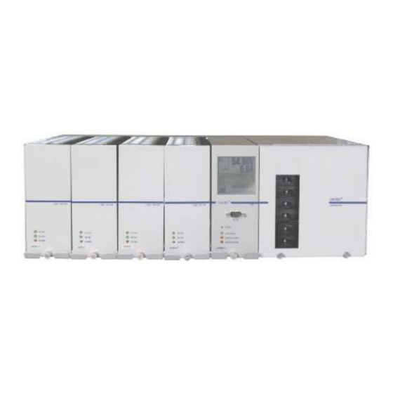
- Page 1 Cordex 48-1kW 23" Shelf for Systems up to 4000W with Distribution Installation & Operation Manual Part # 030-704-B2 Effective: 07/2020 Your Power Solutions Partner member of The Group ™...
- Page 3 Cordex 48-1kW 23" Shelf For Systems Up To 4000W With Distribution 030-704-B2 Rev C The following documents and drawings are included in this manual to provide the necessary information required for installation, operation and fault diagnosis of the unit: • Specifications, Rectifier: 010-606-B1 (010-566-20 non-RoHS) •...
- Page 5 IMPORTANT SAFETY INSTRUCTIONS SAVE THESE INSTRUCTIONS This manual contains important safety and installation instructions for Alpha’s Modular Switched Mode Rectifier System Cordex™ 48-1kW. 1. Please read this manual prior to use to become familiar with the system’s numerous features and operating procedures.
-
Page 6: Table Of Contents
ABLE OF ONTENTS .............................. 1 NTRODUCTION Scope of the Manual ......................... 1 Product Overview ..........................1 Part Numbers and List Options ......................2 ........................... 3 ECTIFIER EATURES Front Panel ............................3 Rear Panel ............................4 True Module Fail Alarm ........................4 Heat Dissipation.......................... - Page 7 6.12 Alarm and Signal Wiring Connections for CXCM ................15 6.13 Analog Inputs for CXCM .........................16 6.14 Digital Inputs for CXCM ........................17 6.15 Alarm (Relay) Outputs for CXCM ....................18 ..............................19 PERATION Main Rectifier States ........................19 Main Rectifier Modes ........................20 Thermal Management ........................20 Factory Ranges and Defaults ......................21 ............................
-
Page 9: Introduction
Introduction Scope of the Manual This instruction manual explains the installation and interconnection of Alpha Technologies’ Cordex 48- 1kW 23” Integrated Shelf System with up to 4000W Output Power and Distribution. Note: To aid the user with installation, frequent reference is made to drawings located at the rear of this manual. -
Page 10: Part Numbers And List Options
Part Numbers and List Options The shelf is available to order under the following part numbers and list options: Description Part Number/List Option Cordex 48-1kW 23" Shelf for Systems up to 4000W with Distribution ......... 030-704-20 [equipped to receive one CXCM controller and four CXRC 48-1kW rectifiers (Figure 1)] ....*List 0 208/220/240Vac input (dual feeds) ...................... -
Page 11: Rectifier Features
Rectifier Features Front Panel Figure 2–Cordex 48-1kW rectifier 2.1.1 LEDs The front panel LEDs provide: • Rectifier status summary, • Rectifier software upgrade in progress indication, • Locate module pattern. Rectifier status summary will show the rectifier alarm status, communication fail status and rectifier on/off status. -
Page 12: Rear Panel
2.1.1.4 LED Activity During Software Upload When a rectifier software upload is in progress, the LEDs will behave in a distinctly different way to indicate new rectifier software is being transferred from the CXC. When a rectifier data transfer is in progress, all three LEDs will flash in a sequence lasting 1.5 seconds. -
Page 13: Wide Ac Range
Wide AC Range A minor alarm is generated when the AC input voltage drops below 180Vac. Output power is reduced linearly below 150Vac to 40% of the rated output power. At a lower voltage the module will shut down and will not restart until the AC is greater than or equal to 150Vac. -
Page 14: Battery Eliminator Operation
2.13 Battery Eliminator Operation Modules maintain all specifications (except where indicated) with or without a battery attached in parallel to the output; however, if a battery or another module supplying DC voltage in parallel is not present, there will be no monitoring or control activity if there is an AC power failure or input fuse failure. 030-704-B2 R... -
Page 15: Cxcm Features
CXCM Features The optional CXCM (Cordex Controller, Modular) can be mounted in the rectifier system shelf and brings advanced monitoring technology to the Cordex series of rectifiers. This compact 4RU system controller is designed for seamless operation and set up of Apha power systems and is equipped with the complete range of Cordex software features, including the following: •... -
Page 16: Analog Input Channels
3.1.2 LEDs The CXCM has three LEDs located on the front panel. These are used to display the alarm status of the power system, CXCM progress and status during startup, and file transfers. 3.1.2.1 Alarm Conditions The CXCM illuminates the LED that corresponds to the system alarm status. The following show the corresponding alarm status for each LED color: Green –... -
Page 17: Digital Input Channels
3.2.3 General-Purpose A set of terminals are provided to monitor a bi-voltage signal that may vary in either polarity from zero; e.g., +/-60Vdc. 3.2.4 Temperature Inputs Two temperature input channels, T1 and T2, provide monitoring of battery temperature and temperature compensation (temp comp) or room/ambient temperature. -
Page 18: Inspection
If the original container is unavailable, make sure the unit is packed with at least three inches of shock-absorbing material to prevent shipping damage. Note: Alpha Technologies is not responsible for damage caused by the improper packaging of returned units. Check for Damage Prior to unpacking the equipment, note any damage to the shipping container. -
Page 19: Installation
Installation This chapter is provided for qualified personnel to install the shelf. Note: To aid the user with installation, frequent reference is made to drawings located at the rear of this manual. Safety Precautions WARNING Hazardous voltages are present at the input of power systems. The DC output from the rectifiers and the battery system though not dangerous in voltage has a high short circuit current capacity that may cause severe burns and electrical arcing. -
Page 20: Wiring And Connections
Wiring and Connections This chapter provides cabling details and notes on cable sizing for DC applications with respect to the shelf. Note: Refer also to drawings at the rear of this manual. Safety Precautions WARNING Hazardous AC voltages may be present. Ensure power at the AC service panel is off before attempting work on the AC connections. -
Page 21: Ac Input Connections
AC Input Connections CAUTION: AC input wires should be routed in flexible or rigid conduit as far away as possible from the DC power wires to minimize EMI disturbances. Ensure all modules are removed from the shelf. Remove the metal cover from the rear of the shelf to expose the wireway for input terminal blocks. -
Page 22: Can Serial Port
6.7.1 DC Distribution Options Consult the foldout drawings located at the rear of the manual. 6.7.1.1 Circuit Breaker Distribution Module The shelf is factory-equipped with distribution of six AM-style bullet-type circuit breakers. See 1.3. Remove the front panel of the distribution module to access the breaker positions and their associated terminals, see Figure 4 below: GMT fuse distribution Circuit breaker distribution terminals... -
Page 23: Cxcm Battery -48V Connection
6.10.2 Ethernet Port for Local Connection Local access is also possible through the Ethernet port connection using a standard crossover cable. 6.10.3 RS-232 Serial (Craft) Port for Local Connection Local access to the CXC is possible through the front panel RS-232 serial port using a null modem cable. See Figure 5 below. -
Page 24: Analog Inputs For Cxcm
CAUTION: to reduce risk of fire, use only 0.129mm (#26 AWG) or larger wire. Terminal Description Default Name Signal Type Range 21-22(common)* Alarm Output 2 LVD2 NC/COM/NO (JP2) 60VDC / 1A 19-20(common)* Alarm Output 3 LVD3 NC/COM/NO (JP3) 60VDC / 1A 17-18(common)* Alarm Output 4 System Minor... -
Page 25: Digital Inputs For Cxcm
6.13.3 General-Purpose Terminals provide connection pairs for various analog inputs such as temperature sensors. These are configured at the time of ordering. The configuration determines whether the signals allowed are to be bipolar (may vary in either polarity from zero; e.g., +/-60VDC) or unipolar (may vary positive from zero; e.g., 0 to +60VDC). -
Page 26: Alarm (Relay) Outputs For Cxcm
6.15 Alarm (Relay) Outputs for CXCM Terminals provide contacts for extending various alarm or control signals. Each relay output can be wired (jumper selectable) for NO or NC operation during an alarm or control condition. See Figure 7. Figure 7–Showing relay connections Relays can be programmed to energize or de-energize during an alarm condition (see CXC Software manual). -
Page 27: Operation
Operation Main Rectifier States Rectifier operation can be broken up into five main states: 1. Off, 2. Start delay, 3. Soft start, 4. Normal operation, 5. Turning off. Each state is characterized as being distinct and necessary for the operation of the rectifier. These states are briefly described below. -
Page 28: Main Rectifier Modes
Main Rectifier Modes In addition to Main Rectifier States, there is a set of Main Rectifier Modes. These modes can be divided into two categories as follows: 7.2.1 Output Voltage Modes Voltage modes can be thought of as modes that, under software control, can directly adjust the output voltage. -
Page 29: Factory Ranges And Defaults
Factory Ranges and Defaults The following table lists the rectifier settings/ranges/defaults; changes are made via the CXC: Setting Range (minimum to maximum) Default Float (FL) Voltage 47.5 – 58.2V Equalize (EQ) Voltage 49.8 – 60.2V Battery Test (BT) Voltage 44 – 52V See note below –... -
Page 30: System Startup
System Startup Refer to Chapter 2 for module installation, rectifier states and modes of operation. After completing the shelf wiring and installation, perform the following startup and test procedure to ensure proper operation: Ensure all power modules are removed from the shelf. Verify correct battery polarity using a voltmeter, and connect battery (if required) to the output of the system. -
Page 31: Maintenance
Maintenance Although very little maintenance is required with Alpha systems, routine checks and adjustments are recommended to ensure optimum system performance. Qualified service personnel shall do repairs. The following table lists a few maintenance procedures for this system. These procedures should be performed at least once a year. -
Page 32: Warranty
10 Warranty Alpha and Outback Energy GmbH warrants all equipment manufactured by it to be free from defects in parts and labor, for a period of two years from the date of shipment from the factory. The warranty provides for repairing, replacing or issuing credit (at AOE’s discretion) for any equipment manufactured by it and returned by the customer to the factory or other authorized location during the warranty period. -
Page 33: Acronyms And Definitions
Acronyms and Definitions Alternating current American wire gauge Controller Area Network Canadian Electrical Code CEMF Counter electro-motive force Canadian Standards Association Cordex series; e.g., CXC for Cordex System Controller Direct current Electronic Industries Alliance HVSD High voltage shutdown Local area network Light emitting diode Low voltage disconnect Normally closed... - Page 34 Specifications for Apha’s Switched Mode Rectifier Cordex 48-1kW Power Module Output Voltage: 40.5 to 58Vdc within rated limits Current: 18.5A @ 54Vdc nominal (20.8A maximum @ 48V) Maximum Power: 1000W continuous/module Static Load Regulation: Better than ±0.5% for any load change within rated limits Dynamic Load Regulation: Better than ±2% for 10% - 90% load step (output shall recover to static limits within 2ms)
- Page 35 Specifications for Apha’s Switched Mode Rectifier Cordex 48-1kW Continued Power Module Input Voltage: 208 to 240Vac nominal Extended Operation: Low: 150 to 90Vac (power de-rated linearly to 40% output) High: 176 to 320Vac (de-rated power factor above 265Vac) Frequency: 50/60Hz nominal (45 to 66Hz) Current: 5.3 to 4.6A (nominal Vac) 7.4A maximum @150Vac...
- Page 36 Specifications for Apha’s Switched Mode Rectifier Cordex 48-1kW Continued Referenced Standards EN 300 386-2 EMC and ERM; Telecommunication Network Equipment EN 55022 (CISPR 22): 1998 Information Technology Equipment – Radio Disturbance Characteristics – Limits and Methods of Measurement EN 61000-3-2:2000 Harmonic Current Emissions EN 61000-3-3:1995 Voltage Fluctuations and Flicker...
- Page 37 REVISIONS DESCRIPTION REV BY DATE APPD 11.95 303.4 6.00 152.4 LIST 93 SIDE ACCESS RJ-45 (-) .73 18.6 LIST 90 ISOMETRIC VIEW BLANK MODULE BREAKER P/N 010-566-20 P/N 018-557-20 DISTRIBUTION 48V-1kW CXRC CXCM SUPERVISORY TOP VIEW 6.98 177.3 5.485 139.32 3.735 94.87 3.235 82.17 1.485 37.72...
- Page 38 REVISIONS DESCRIPTION REV BY DATE APPD TO SHOW LIST OPTION CHANGES, 04/06 AND A TITLE CHANGE; LIST 0,6 - 4 MODULE WITH CXC CONTROLLER & DISTRIBUTION AC INPUT KNOCKOUT PLATE (REVERSIBLE) INPUTS E2 - COMMON (+) E1 - LIVE (-) 1.125"...
- Page 39 REVISIONS JUMPER SETTINGS FOR JP2-8 DESCRIPTION REV BY DATE APPD LIST 0 : 5 MDL e/w CXC NORMALLY NORMALLY OPEN CLOSED ETHERNET RJ45 PINOUT (J3) #18-26 AWG WIRE SYSTEM FAIL OUTPUT DIGITAL INPUTS 1. TX+ 2. TX- ALARM 3. RX+ OUTPUTS 4.
- Page 40 REVISIONS DESCRIPTION REV BY DATE APPD 6 POS'N CIRCUIT BREAKER COMMON COMMON THESE DESIGNS AND SPECIFICATIONS ARE THE PROPERTY OF COMMON ARGUS TECHNOLOGIES AND SHALL NOT BE COPIED OR USED FOR MANUFACTURING WITHOUT ITS WRITTEN CONSENT. 2004/06 MATERIAL DESIGN 2004/06 DRAWN 2004/ CHECKED...
- Page 41 REVISIONS DESCRIPTION REV BY DATE APPD LOAD BREAKERS TO BATTERY (+) E2 - COMMON (+) TO DISTRIBUTION MODULE E1 - LIVE(-) TO BATTERY (-) COMMON LIST 80 - 6 LOAD CB POS'N LIST 85 - DUAL OUTPUT ADAPTERS ( TB1 A.C. WIRES HIDDEN ) LOAD BREAKERS LOAD...
- Page 44 Worldwide Corporate Offices Headquarter Germany France and Benelux Russia Eastern Europe fbnl@alpha-outback-energy.com ee@alpha-outback-energy.com russia@alpha-outback-energy.com Hansastrasse 8 D-91126 Schwabach Tel: +49 9122 79889 0 Middle East Spain Africa Fax: +49 9122 79889 21 me@alpha-outback-energy.com spain@alpha-outback-energy.com Mail: info@alpha-outback-energy.com africa@alpha-outback-energy.com Alpha and Outback Energy GmbH reserves the right to make changes to the products and information contained in this document without notice. Copyright © 2020 Alpha and Outback Energy GmbH. All Rights reserved.
Need help?
Do you have a question about the ALPHA OUTBACK ENERGY Cordex 48-1kW and is the answer not in the manual?
Questions and answers