
Subscribe to Our Youtube Channel
Related Manuals for Alpha Technologies 030-706-J0


Summary of Contents for Alpha Technologies 030-706-J0
- Page 1 Cordex 48-1kW 19" Shelf For Systems Up To 6000W Installation & Operation Manual Part # 030-706-J0 Effective: 02/2014 Your Power Solutions Partner member of The Group ™...
- Page 3 Keep it in a safe place. Review the drawings and illustrations contained in this manual before proceeding. If there are any questions regarding the safe installation or operation of this product, contact Alpha Technologies or the nearest Alpha representative. Save this document for future reference.
- Page 4 Electrical Safety WARNING! Hazardous voltages are present at the input of power systems. The DC output from rectifiers and batteries, though not dangerous in voltage, has a high short-circuit current capacity that may cause severe burns and electrical arcing. Before working with any live battery or power system, follow these precautions: •...
- Page 5 Inspeccione los dibujos y las ilustraciones contenidas en este manual antes de continuar. Si existe cualquier pregunta relacionada con la instalación u operación segura de este producto, póngase en contacto con Alpha Technologies o con su representante de Alpha más cercano. Guarde este documento para referencia futura.
- Page 6 Seguridad Eléctrica ¡ADVERTENCIA ! Hay voltajes peligrosos en la entrada de los sistemas de alimentación. La salida de CC de rectificadores y baterías, si bien no es peligrosa en cuanto al voltaje, cuenta con una alta capacidad de conducción de cortocircuito que puede causar quemaduras graves y arcos eléctricos.
- Page 7 En cas de questions sur l'installation ou le fonctionnement en toute sécurité de ce produit, contactez Alpha Technologies ou le représentant d'Alpha le plus près. Conservez ce document pour référence future. Symboles de Sécurité...
- Page 8 Sécurité Electrique AVERTISSEMENT ! Des tensions dangereuses sont présentes à l’entrée des systèmes électriques. La sortie CC des redresseurs et des batteries, bien que non dangereuse en termes de tension, a une capacité de courant de court-circuit élevée qui peut causer de graves brûlures et des arcs électriques.
- Page 9 Bewahren Sie es an einem sicheren Ort auf. Sehen Sie sich die Zeichnungen und Illustrationen in diesem Handbuch genau an, bevor Sie fortfahren. Sollten Sie Fragen zur sicheren Installation oder zum Betrieb dieses Produkts haben, wenden Sie sich bitte an Alpha Technologies oder den nächstgelegenen Alpha-Vertreter. Bewahren Sie dieses Dokument für den zukünftigen Gebrauch auf.
- Page 10 Elektrische Sicherheit WARNUNG! Am Punkt der Stromeinspeisung liegen gefährliche Spannungen vor. Der Gleichstromausgang von Gleichrichtern und Batterien weist zwar keine gefährliche Spannung auf, die Kurzschlussstrom-Kapazität ist jedoch sehr hoch, was zu ernsthaften Verbrennungen und Lichtbögen führen kann. Befolgen Sie die folgenden Vorsichtsmaßnahmen, bevor Sie mit einer spannungsführenden Batterie oder einem Stromversorgungssystem arbeiten: •...
- Page 11 Cordex 48-1kW 19" Shelf For Systems Up To 6000W Models: 030-706-20 030-707-20 The following documents and drawings are included in this manual to provide the necessary information re- quired for installation, operation and fault diagnosis of the unit: • Specifications, 19" Shelf: 030-706-B1 •...
-
Page 12: Table Of Contents
ABLE OF ONTENTS ................................1 NTRODUCTION Scope of the Manual ............................. 1 Product Overview ............................1 Part Numbers and List Options ........................2 ..............................3 ECTIFIER EATURES Front Panel ..............................3 Rear Panel ..............................4 True Module Fail Alarm ..........................4 Heat Dissipation ............................ - Page 13 Thermal Management ..........................21 Factory Ranges and Defaults ........................22 ..............................23 YSTEM TARTUP Check System Connections ........................23 Verify AC and Power the Shelf ........................23 Check Battery Polarity and Connect ......................23 CXC Reset ..............................23 ................................24 AINTENANCE 10 W ................................
-
Page 15: Introduction
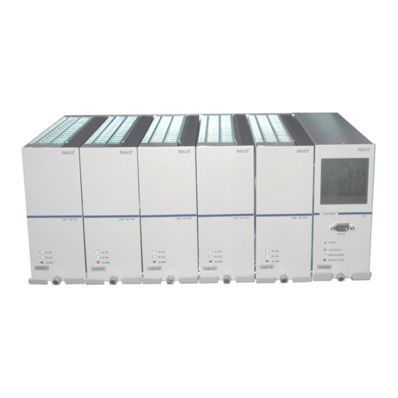
The CXC allows the user to set up, control and monitor the entire power system and ancillary components from one central, easy-to-use source. Details of controller operation are provided in the current version software manual. Figure 1–Cordex 5000W system with CXCM 030-706-J0 Rev B Page 1 of 26... -
Page 16: Part Numbers And List Options
Gray finish with blue silkscreen ........................*List 50 * Default option The above information is valid at the time of publication. Consult factory for up-to-date ordering information. Figure 2–Cordex 6000W system (no CXCM) 030-706-J0 Rev B Page 2 of 26... -
Page 17: Rectifier Features
The bottom LED (red) is on continuously in the event of an active Module Fail alarm. The LED will flash (~2Hz) when a minor alarm is detected. The LED remains off in the absence of an alarm. 030-706-J0 Rev B Page 3 of 26... -
Page 18: Rear Panel
A battery connected to the output of the rectifier will draw current when the voltage ramp occurs. Therefore the rectifier fail alarm will not be generated with a battery connected. 030-706-J0 Rev B Page 4 of 26... -
Page 19: Wide Ac Range
DC voltage in parallel is not present, there will be no monitoring or control activity if there is an AC power failure or input fuse failure. 030-706-J0 Rev B Page 5 of 26... -
Page 20: Cxcm Features
This graphical user interface (GUI) allows the operator to interact with screen selectable items using a fingertip. Touch screen Reset (RST) button RS-232 (craft port) System status LEDs Figure 4–Cordex CXCM model system controller front panel 030-706-J0 Rev B Page 6 of 26... -
Page 21: Analog Input Channels
The CXCM software is pre-configured to monitor I1 for load current using an external 50mV current shunt. 3.2.3 General-Purpose A set of terminals are provided to monitor a bi-voltage signal that may vary in either polarity from zero; e.g., +/-60Vdc. 030-706-J0 Rev B Page 7 of 26... -
Page 22: Digital Input Channels
All alarming and control of Cordex rectifiers is accomplished with a CXC via a CAN bus. A step-by-step connection wizard – provided to establish remote communications with your CXC – is available via the Apha website (www.alph.ca). 030-706-J0 Rev B Page 8 of 26... -
Page 23: Inspection
Continue the inspection for any internal damage. In the unlikely event of internal damage, please inform the carrier and contact Apha Technologies for advice on the impact of any damage. Verify that you have all the necessary parts per your order for proper assembly. 030-706-J0 Rev B Page 9 of 26... -
Page 24: Installation
To remove modules, loosen the screw on the bottom of the faceplate. Grasp handle and pull out, sliding the module away from the rear connectors and out of the shelf. 030-706-J0 Rev B Page 10 of 26... -
Page 25: Wiring And Connections
Crimping tool (optional for large gauge wire) • Socket and rachet set (Imperial measure) • Anti-static wrist strap • Computer (laptop) with Microsoft Internet Explorer 6 or greater • Crossover cable RJ-45 (for access using the Ethernet port). 030-706-J0 Rev B Page 11 of 26... -
Page 26: Power System Chassis Ground
Check again that the ampacity rating of the cable meets the requirement for the installation application. Consult local electrical codes (NEC, CEC, etc.) for guidelines. If required, increase the size of the cable to meet the code. 030-706-J0 Rev B Page 12 of 26... -
Page 27: Dc Output Connections
The jumper (P1) allows setting of the CAN OUT to be open to next shelf or TERMINATED if last shelf on CAN bus, as shown here: Figure 6–CAN ports for multiple shelf connections with CXCM 030-706-J0 Rev B Page 13 of 26... - Page 28 The jumper (P1) allows setting of the CAN OUT to be open to next shelf or TERMINATED if last shelf on CAN bus, as shown here: Figure 7–CAN ports for multiple shelf connections with CXCP (CXCR typical) 030-706-J0 Rev B Page 14 of 26...
-
Page 29: Network Connection And Remote Communications Via Cxc
RS-232 Serial (Craft) Port for Local Connection Local access to the CXC is possible through the front panel RS-232 serial port using a null modem cable. See Figure 8. Figure 8–NULL modem pinouts 030-706-J0 Rev B Page 15 of 26... -
Page 30: Alarm And Signal Wiring Connections For Cxcm
Battery –48V: connect to battery only when using a battery disconnect device NOTE: To aid the user with installation, frequent reference is made to drawings located at the rear of this manual. Custom configurations may be detailed within the Apha power system documentation package. 030-706-J0 Rev B Page 16 of 26... - Page 31 Both NO and NC contacts are available for this particular relay. Apha #707-340-20 for the CXCM. See Customer Connections drawing at the rear of this manual. 030-706-J0 Rev B Page 17 of 26...
- Page 32 See CXC Software manual for detailed instruction on programming. Voltage Level (VDC) Voltage Level (VDC) Voltage Range (VDC) Considered As “0” (Off) Considered As “1” (On) 0—60 0—3 18—60 (system voltage setting) Table C–Voltage level definitions for digital inputs 030-706-J0 Rev B Page 18 of 26...
- Page 33 Temperature Sensor Terminals, of the general purpose grouping, may be configured as temperature input channels and provide connections for up to two temperature sensors. A voltage is supplied to these terminals for sensor measurements. 030-706-J0 Rev B Page 19 of 26...
-
Page 34: Operation
The Turning Off state is entered because a short delay is required before the rectifier actually turns off to take care of any initialization requirements. When this short delay has elapsed, a transition to the Off state is made. 030-706-J0 Rev B Page 20 of 26... -
Page 35: Main Rectifier Modes
For example, the shelf can deliver 85% load at 40°C, with some alarms active. However, in higher ambient temperatures, load reduction may be necessary. 030-706-J0 Rev B Page 21 of 26... -
Page 36: Factory Ranges And Defaults
Remote Shutdown Enable/Disable Enable Ramp Test Enable/Disable Enable Table F–Cordex 48-1kW rectifier factory ranges and defaults NOTE: OVP cannot be set below the present system/FL/EQ/BT voltage setting or the safe mode voltage of 51.4V. 030-706-J0 Rev B Page 22 of 26... -
Page 37: System Startup
A reset button is located on the front panel of the CXC for restarting the microprocessor. It takes approximately 15 seconds before the display reappears after pressing the reset button. To protect against accidental load disconnect, see 6.10.1.1. 030-706-J0 Rev B Page 23 of 26... -
Page 38: Maintenance
Procedure Date Completed Clean ventilation openings Inspect all system connections (re-torque as necessary) Verify alarm/control settings Verify alarm relay operation Table G–Sample maintenance log NOTE: There are no field replaceable parts. 030-706-J0 Rev B Page 24 of 26... -
Page 39: 10 Warranty
10 Warranty Alpha Technologies Ltd. warrants all equipment manufactured by it to be free from defects in parts and labor, for a period of two years from the date of shipment from the factory. The warranty provides for repairing, replacing or issuing credit (at Alpha’s discretion) for any equipment manufactured by it and returned by the customer to the... -
Page 40: Acronyms And Definitions
High voltage shutdown Light emitting diode Low voltage disconnect Normally closed National Electrical Code (for the USA) Normally open OSHA Occupational Safety & Health Administration Over voltage protection Random access memory Underwriters Laboratories 030-706-J0 Rev B Page 26 of 26... - Page 41 Specifications for Apha Cordex 48-1kW 19" Shelf System Basic Unit, Shelf Output: 111A @ 54Vdc nominal (124.8A maximum @48V) Recommended Feeder Breaker Single Phase: 15A, #12AWG, 90 deg.C wire at 30 deg. C ambient (per rectifier) [refer also to AC Feeder Protection/Sizing section of the manual] Mechanical Dimensions*: 177.3mm H x 444.5mm W x 303.4mm D (rectifier front panel 18.8mm D)
- Page 42 Specifications for Apha Cordex 48-1kW 19" Shelf System Continued Basic Unit, CXCM Input Voltage: 17 to 65Vdc within rated limits Current: <100mA @ 48Vdc <200mA @ 24Vdc MTBF: >430,000 hours @ 30°C (86°F) EMC: The unit meets requirements of: ICES-003 Class B EN 55022 Class B (CISPR 22) EN 61000-4-2 ESD EN 61000-4-3 Radiated Immunity...
- Page 43 Specifications for Apha Cordex 48-1kW 19" Shelf System Continued Hardware Specifications, CXCM CPU: Coldfire RAM: Flash: 4MB standard, 8MB optional Display: 160 x 160 pixel grayscale LCD Front Panel Controls: Reset button and touch panel (display and input device) LED’s: System OK (Green) Power System Minor Alarm (Yellow) Power System Major Alarm / Controller Fail (Red)
- Page 44 Specifications for Apha’s Switched Mode Rectifier Cordex 48-1kW Power Module Output Voltage: 40.5 to 58Vdc within rated limits Current: 18.5A @ 54Vdc nominal (20.8A maximum @ 48V) Maximum Power: 1000W continuous/module Static Load Regulation: Better than ±0.5% for any load change within rated limits Dynamic Load Regulation: Better than ±2% for 10% - 90% load step (output shall recover to static limits within 2ms)
- Page 45 Specifications for Apha’s Switched Mode Rectifier Cordex 48-1kW Continued Power Module Input Voltage: 208 to 240Vac nominal Extended Operation: Low: 150 to 90Vac (power de-rated linearly to 40% output) High: 176 to 320Vac (de-rated power factor above 265Vac) Frequency: 50/60Hz nominal (45 to 66Hz) Current: 5.3 to 4.6A (nominal Vac) 7.4A maximum @150Vac...
- Page 46 Specifications for Apha’s Switched Mode Rectifier Cordex 48-1kW Continued Referenced Standards EN 300 386-2 EMC and ERM; Telecommunication Network Equipment EN 55022 (CISPR 22): 1998 Information Technology Equipment – Radio Disturbance Characteristics – Limits and Methods of Measurement EN 61000-3-2:2000 Harmonic Current Emissions EN 61000-3-3:1995 Voltage Fluctuations and Flicker...
- Page 47 03070605B__.sch-1 - Fri Mar 04 14:39:15 2005...
- Page 48 03070605B__.sch-2 - Fri Mar 04 14:39:49 2005...
- Page 49 REVISIONS DESCRIPTION REV BY DATE APPD 11.95 303.4 6.00 152.4 LIST 23 23" MID-MOUNT LIST 19 19" MID-MOUNT LIST 25 23" FLUSH-MOUNT (-) .74 18.8 FRONT RIGHT ISOMETRIC VIEW LIST 90 : MODULE BLANK P/N 010-566-20 P/N 018-557-20 48V-1kW CXRC CXCM SUPERVISORY TOP VIEW 5.485 139.32...
- Page 50 REVISIONS DESCRIPTION REV BY DATE APPD SPECIFIED RECTIFIERS FED BY TB1 & TB2 M.P. 2005/11 C UPDATED AC I/P TERMINAL BLOCK M.P. 2007/09 FROM LINE 2 TO L2/N LIST 0,6 : 5 MODULE WITH CXC CONTROLLER AC INPUT KNOCKOUT PLATE (REVERSIBLE) CXCM BACKPLANE (707-340-20)
- Page 51 REVISIONS DESCRIPTION REV BY DATE APPD LIST 0,6,81 - 6 MODULE AC INPUT KNOCKOUT PLATE (REVERSIBLE) INPUTS OUTPUT 1.125" KO ACCEPTS 3/4" FITTING/CONDUIT .875" KO ACCEPTS 1/2" FITTING/CONDUIT #1/4-20 CHASSIS GROUND USES 1/4-20 x 5/8" OUTPUT LUGS TIGHTEN TO 8 FT-LB #6-32 SCREWS JUMPER SETTING FOR P1 CAN TERMINATED...
- Page 52 REVISIONS JUMPER SETTINGS FOR JP2-8 DESCRIPTION REV BY DATE APPD LIST 0 : 5 MDL W CXC NORMALLY NORMALLY OPEN CLOSED ETHERNET RJ45 PINOUT (J3) #18-26 SYSTEM FAIL OUTPUT DIGITAL INPUTS 1. TX+ 2. TX- ALARM 3. RX+ OUTPUTS 4. COM1 5.
- Page 53 03070705B__.sch-1 - Fri Mar 04 14:43:46 2005...
- Page 54 03070705B__.sch-2 - Fri Mar 04 14:44:27 2005...
- Page 55 03070705B__.sch-3 - Fri Mar 04 14:44:54 2005...
- Page 56 REVISIONS DESCRIPTION REV BY DATE APPD 11.95 303.4 (-) .74 18.8 LIST 90 : MODULE BLANK FRONT ISOMETRIC VIEW P/N 010-566-20 P/N 018-557-20 48V-1kW CXRC CXCM SUPERVISORY TOP VIEW 5.485 139.32 3.735 94.87 6.98 177.3 3.235 82.17 1.485 37.72 THESE DESIGNS AND SPECIFICATIONS ARE THE PROPERTY OF ARGUS TECHNOLOGIES AND SHALL NOT BE COPIED OR USED FOR MANUFACTURING WITHOUT ITS WRITTEN CONSENT.
- Page 57 REVISIONS REV BY DESCRIPTION DATE APPD ADDED PG3, LIST0,9,82, 3 FEEDS 2004/12 UPDATED AC I/P TERM BLOCK LIST 0,6 : 5 MODULE WITH CXC CONTROLLER AC INPUT KNOCKOUT PLATE (REVERSIBLE) CXCM BACKPLANE (707-340-20) AC INPUTS E2 COMMON (+) E1 LIVE ( - DC OUTPUT 1.125"...
- Page 58 LIST 0,6,81 - 6 MODULE , DUAL FEEDS AC INPUT KNOCKOUT PLATE (REVERSIBLE) AC INPUTS E2 COMMON (+) E1 LIVE ( - DC OUTPUT 1.125" KO ACCEPTS 3/4" FITTING/CONDUIT 0.875" KO ACCEPTS 1/2" FITTING/CONDUIT #1/4-20 CHASSIS GROUND USES 1/4-20 x 5/8" OUTPUT LUGS TIGHTEN TO 8 FT-LB #6-32 SCREWS JUMPER SETTING FOR P1...
- Page 59 LIST 0,9,82 - 6 MODULE ,THREE FEEDS AC INPUT KNOCKOUT PLATE (REVERSIBLE) AC INPUTS E2 COMMON (+) E1 LIVE ( - 1.125" KO DC OUTPUT ACCEPTS 3/4" FITTING/CONDUIT 0.875" KO ACCEPTS 1/2" FITTING/CONDUIT #1/4-20 CHASSIS GROUND USES 1/4-20 x 5/8" OUTPUT LUGS TIGHTEN TO 8 FT-LB #6-32 SCREWS JUMPER SETTING FOR P1...
- Page 60 JUMPER SETTINGS FOR JP2-8 NORMALLY NORMALLY OPEN CLOSED LIST 0 : 5 MDL e/w CXC ETHERNET RJ45 PINOUT (J3) #18-26 AWG WIRE 1. TX+ SYSTEM 2. TX- FAIL 3. RX+ OUTPUT 4. COM1 5. COM1 6. RX- DIGITAL 7. COM2 INPUTS 8.
- Page 64 Canada and USA: 1-888-462-7487 International: +1-604-436-5547 Visit us at www.alpha.ca Due to continuing product development, Alpha Technologies reserves the right to change specifications without notice. Copyright © 2014 Alpha Technologies. All Rights Reserved. Alpha® is a registered trademark of Alpha Technologies.
Need help?
Do you have a question about the 030-706-J0 and is the answer not in the manual?
Questions and answers