Table of Contents
Advertisement
Quick Links
Fragen? Jetzt Kontakt aufnehmen.
Headquarter Germany
Hansastrasse 8
D–91126 Schwabach
Germany
Die Firma Alpha Technologies GmbH behält sich das Recht vor, Änderungen an den hier enthaltenen Produkten und Informa-
tionen vorzunehmen, ohne Vorankündigung. Copyright © 2020 Alpha und Outback Energy GmbH. Alle Rechte vorbehalten.
Tri Power X31 HE – 10 to 20 kVA
U S E R M A N U A L
Offices
Eastern Europe | Middle East
Belgium | France
Spain | Africa
Kontakt
T: +49 9122 79889 0
F: +49 9122 79889 21
M: service@alphatechnologies.de
Advertisement
Table of Contents

Related Manuals for Alpha Technologies Tri Power X31 HE


Summary of Contents for Alpha Technologies Tri Power X31 HE
- Page 1 Belgium | France Germany Spain | Africa M: service@alphatechnologies.de Die Firma Alpha Technologies GmbH behält sich das Recht vor, Änderungen an den hier enthaltenen Produkten und Informa- tionen vorzunehmen, ohne Vorankündigung. Copyright © 2020 Alpha und Outback Energy GmbH. Alle Rechte vorbehalten.
- Page 2 NTRODUCTION Thank you for choosing this product. Our company is specialized in the design, development and production of uninterruptible power supplies (UPS). The TRIPOWER X31 HE described in this manual is a high-quality, meticulously-designed product, built to guarantee the best performance.
- Page 3 ONTENTS OVERVIEW TRIPOWER X31 HE PTIONAL MALL VIEWS TRIPOWER X31 HE TANDARD VIEWS TRIPOWER X31 HE C IEW OF THE ONNECTIONS IEW OF THE ONTROL ANEL ATTERY OPTIONAL EPARATE YPASS NPUT OPTIONAL NTERNAL RANSFORMER DDITIONAL NTERNAL ATTERY HARGERS INSTALLATION TRIPOWER X31 HE TORING THE AND THE ATTERY...
-
Page 4: Table Of Contents
EMOTE PANEL OPTIONAL ESCRIPTION RELIMINARY PERATIONS OWERING ON FOR THE IRST OWERING ON FROM THE AINS OWERING ON FROM THE ATTERY TRIPOWER X31 HE OWERING OFF THE RAPHIC ISPLAY ISPLAY ENUS PERATING ODES (SWMB) AINTENANCE YPASS EDUNDANT UXILIARY OWER UPPLY FOR UTOMATIC YPASS ROGRAMMABLE... - Page 5 OVERVIEW The new three-phase/single-phase TRIPOWER X31 HE 10 – 15 – 20 kVA series (VFI-SS-111 type) have been designed using the latest technology available today so as to guarantee users maximum performance. The use of the new control PCBs based on multiprocessor architecture (DSP + P inside) together with high frequency IGBT technology offers excellent performance both in the input stage (absorbed current harmonic distortion ≤...
- Page 6 TRIPOWER X31 HE PTIONAL MALL VIEWS Battery start button (COLD START) Brake rod Manual bypass switch Slots for accessory communication cards Battery fuse holder isolator Communication ports (AS400, USB, RS232) Powershare sockets (10A max. total on the two Output switch sockets) and relative protection Separate bypass switch (optional) Ventilation fans...
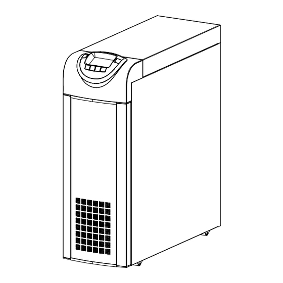
- Page 7 TRIPOWER X31 HE TANDARD VIEWS Battery start button (COLD START) Brake rod Manual bypass switch Slots for accessory communication cards Battery fuse holder isolator Communication ports (AS400, USB, RS232) Powershare sockets (10A max. total on the two Output switch sockets) and relative protection Separate bypass switch (optional) Ventilation fans Input switch...
- Page 8 TRIPOWER X31 HE C IEW OF THE ONNECTIONS Connection for the R.E.P.O command (Remote Emergency Power Off) (see previous page for the Standard version) Power connections: BATTERY, INPUT, SEPARATE BYPASS (optional), OUTPUT Connection for remote maintenance bypass command Connection for external Battery Box temperature probe Connection for external synchronization signal Slot for power relay board Area for the single-phase short-circuit bar...
- Page 9 IEW OF THE ONTROL ANEL Graphic display Function keys * Left-hand LEDs area: Right-hand LEDs area: Mains power LED Stand-by / alarm LED Battery power LED Battery low LED Load on bypass LED ECO mode LED * The function of each key is indicated at the bottom of the display and varies according to the menu used. - 9 -...
- Page 10 ATTERY OPTIONAL THE BATTERY BOX IS AN OPTIONAL ACCESSORY. THIS TRIPOWER X31 HE RANGE HAS BATTERY BOX VERSIONS OF THE SAME SIZE AND MATCHING STYLE. The Battery Box contains batteries that increase the operating time of the UPS during prolonged black-outs. The number of batteries contained in it will vary according to the type of TRIPOWER X31 HE to which the Battery Box is to be installed.
- Page 11 EPARATE YPASS NPUT OPTIONAL (OPTIONAL) VERSION OF THE TRIPOWER X31 HE SERIES HAS SEPARATE BYPASS AND INPUT LINES. The TRIPOWER X31 HE series with separate Bypass ensures a separate connection between the input and bypass lines. The TRIPOWER X31 HE output is synchronised with the bypass line so as to safeguard against incorrect voltage changeovers in the alternate phases, in the event of automatic bypass or closing of the maintenance switch (SWMB).
- Page 12 INSTALLATION ALL THE OPERATIONS DESCRIBED IN THIS SECTION ARE TO BE PERFORMED EXCLUSIVELY BY QUALIFIED STAFF. The company declines all liability for damage caused by incorrect connections or operations not described in this manual. TRIPOWER X31 HE TORING THE AND THE ATTERY The storage room must respect the following conditions: Temperature:...
- Page 13 LECTROMAGNETIC OMPATIBILITY This TRIPOWER X31 HE product conforms to the current electromagnetic compatibility (EMC) regulations (C2 class). It may cause radio interference in the home environment. The user may have to adopt supplementary measures. This product is for professional use in industrial and commercial environments. Connections to USB and RS232 connectors must be made with the cables provided, or at least with shielded cables less than 3 metres long.
- Page 14 TRIPOWER X31 HE EMOVING THE AND THE ATTERY OX FROM THE ALLET PTIONAL MALL IZE VERSION Cut the straps and remove the cardboard box by sliding it upwards Remove the accessory box and side blocks. NOTE 1: You will find the accessory box either inside the door of the TRIPOWER X31 HE or on top of the UPS.
- Page 15 TANDARD ERSION WARNING: IN ORDER TO AVOID DAMAGE TO PERSONS AND/OR TO THE MACHINES, PLEASE FOLLOW SCRUPULOUSLY THE INDICATIONS GIVEN BELOW. SOME OF THE FOLLOWING OPERATIONS REQUIRE TWO PEOPLE. Cut the straps and slide the cardboard box off Remove the two brackets securing the UPS to the pallet by the unit pulling upwards.
- Page 16 RELIMINARY HECK OF ONTENTS Having opened the package, start by checking the contents. TRIPOWER X31 HE BATTERY BOX (optional) Metal slides, Guarantee document, User manual, Cd- Metal slides, Guarantee document, Cable for connecting rom containing the UPS management software, Serial the Battery Box to the TRIPOWER X31 HE (Optional Small Size version only), 4 battery fuses (to be inserted connecting cable, 4 battery fuses (to be inserted in the...
- Page 17 LECTRICAL ONNECTIONS WARNING: a 4-wire three-phase distribution system is required for the three-phase input connection. The UPS must be connected to a power supply line made up of 3 phases + neutral + PE (protective earth) of TT, TN or IT type.
- Page 18 TRIPOWER X31 HE without any variation in neutral condition and with separate bypass input TRIPOWER X31 HE with galvanic isolation and with separate bypass input TRIPOWER X31 HE with galvanic isolation at output and separate bypass input - 18 -...
- Page 19 Separate bypass: if the separate bypass option is present, protective devices must be present on both the main power supply line and the bypass line. Note: the neutral of the input line and that of the bypass are commoned inside the equipment, so they must refer to the same potential.
- Page 20 TRIPOWER X31 HE NTERNAL ROTECTIVE EVICES OF THE The table below shows the sizes of the isolators of the UPS and the sizes of the battery fuses (SWBATT): these devices are accessible from the front of the UPS. There are also indications about the internal fuses (not accessible) protecting the input and output lines and the maximum input and rated output currents.
- Page 21 XTERNAL ROTECTIVE EVICES MAGNETOTHERMAL As explained previously, the TRIPOWER X31 HE has protection devices for output faults as well as for internal faults. In order to set up the power line, install a magnetothermal switch upstream from the UPS with intervention curve C. Please follow the indications in the table below: Automatic external protections Mains input...
- Page 22 ROSS ECTION OF THE ABLES The manufacturer recommends that the INPUT/OUTPUT and BATTERY cables pass under the TRIPOWER X31 HE unit. Please refer to the following table for the minimum cross-sections to be used for the input and output cables. Cable sizes (mm INPUT mains /...
- Page 23 ONNECTIONS OF THE MODEL WITH SEPARATE BYPASS The very first connection must be the protection conductor or the earth cable which should be inserted in the terminal marked PE. The TRIPOWER X31 HE must be earthed before use. Connect the input and output cables to the terminal board as shown in the figure below: THE INPUT AND BYPASS NEUTRAL MUST ALWAYS BE CONNECTED.
- Page 24 R.E.P.O. This isolated input is used to turn off the TRIPOWER X31 HE remotely in case of emergency. The UPS is supplied from the factory with the “Remote Emergency Power Off” (R.E.P.O.) terminals short-circuited (see "View of TRIPOWER X31 HE connections” ref.15). If it is to be installed, remove the short-circuit and connect to the normally closed contact of the stop device using a cable that provides a double isolation connection.
- Page 25 ONNECTING THE EMOTE AINTENANCE YPASS An additional maintenance bypass may be installed on a peripheral switchboard, for example, to enable the TRIPOWER X31 HE to be replaced without interrupting the power supply to the load. It is absolutely essential to connect the "SERVICE BYPASS" terminal (see "View of TRIPOWER X31 HE connections"...
- Page 26 DIAGRAM SHOWING REMOTE INSTALLATION OF THE MAINTENANCE BYPASS ON THE THREE PHASE – SINGLE PHASE MODEL WITH SEPARATE BYPASS Peripheral electric control panel TRIPOWER X31 HE internal connections magneto-thermal switch compliant with the indications given in the “External Protection LINE switch: Devices”...
- Page 27 TRIPOWER X31 HE ONNECTING THE ATTERY OX TO THE THE CONNECTION BETWEEN THE TRIPOWER X31 HE AND THE BATTERY BOX MUST BE MADE WITH THE DEVICES POWERED OFF AND UNPLUGGED FROM THE MAINS TRIPOWER X31 HE POWER-OFF PROCEDURE: Turn off all devices connected to the TRIPOWER X31 HE or use the remote bypass option (if installed). ...
- Page 28 ULTIPLE XPANSIONS Several Battery Boxes can be connected in a cascade to ensure prolonged autonomy. The connections should be made as shown here below: WARNING (only for single UPS): No more than one UPS may be connected to each Battery Box or to more than one Battery Box connected in a cascade.
-
Page 29: Remote Panel ( Optional )
XTERNAL EMPERATURE ROBE This NON ISOLATED input may be used to measure the temperature inside a remote Battery Box. The special kit provided by the manufacturers must be used: any methods not conforming to specifications may cause faults or breakdowns in the equipment. To install, connect the cable included in the special kit to the "EXT BATTERY TEMP PROBE"... -
Page 30: Use
ESCRIPTION The purpose of a TRIPOWER X31 HE is to ensure a perfect power supply voltage for the devices connected to it irrespective of whether mains power is present or not. Once connected and powered, the UPS generates a sinusoidal alternating voltage with a stable amplitude and frequency, irrespective of the changes and/or variations occurring on the electricity network. -
Page 31: Preliminary Operations
RELIMINARY PERATIONS Visual check of the connection Check that all the connections have been made strictly following the indications given in the "Connections" paragraph. Check that the "1/0" button is in its "0" position (see "Front Views of the TRIPOWER X31 HE" point 5). Check that all the isolators are open. -
Page 32: Powering On For The First Time
OWERING ON FOR THE IRST If present, set the “1/0” switch to “1” and wait for a few seconds. Check that the display is turned on and the UPS enters "STAND-BY" mode. Check that no error messages appear indicating that the input cables do not respect the correct cyclic phase sense (for three- phase input only). -
Page 33: Powering On From The Mains
OWERING ON FROM THE AINS Power the TRIPOWER X31 HE by closing the SWIN input switch and leaving the SWMB maintenance switch open; if present, set the “1/0” switch to “1”. After a few moments, the TRIPOWER X31 HE is turned on, the capacitors are precharged and the "Lock / stand-by" LED blinks: The UPS is in stand-by mode. -
Page 34: Graphic Display
RAPHIC ISPLAY At the centre of the control panel there is a large graphic display, which provides, in the foreground and in real time, a detailed overview of the current status of the UPS. Directly from the control panel you can turn the UPS on/off, view the electrical values of the mains, output, battery, etc., and make the main machine settings. -
Page 35: Display Menus
ISPLAY ENUS - 35 -... -
Page 36: Operating Modes
PERATING ODES The mode that guarantees maximum protection for the load is ON LINE mode, in which the energy for the load is converted twice and is generated perfectly sinusoidal at the output with the frequency and voltage set by the fine digital control of the DSP irrespective of the input (V.F.I.). -
Page 37: Redundant Auxiliary Power Supply For Automatic Bypass
EDUNDANT UXILIARY OWER UPPLY FOR UTOMATIC YPASS The TRIPOWER X31 HE is equipped with a redundant auxiliary power supply that enables the UPS to run on an automatic bypass even when a failure occurs in the main auxiliary power supply. If a fault occurs in the UPS shutting off the main auxiliary power supply, the load is powered by the automatic bypass. -
Page 38: Configuring The Tripower X31 He
TRIPOWER X31 HE ONFIGURING THE The table below illustrates all the possible settings at your disposal to tailor the TRIPOWER X31 HE to best satisfy your needs. (Control Panel) = Indicates that the configuration can be changed not only from the configuration software but also from the control panel. - Page 39 FUNCTION DESCRIPTION DEFAULT POSSIBLE SETTINGS MOD. Advanced Functions Selects the allowed input ± 0.25% frequency range for the ± 0.5% Input frequency switch to bypass and ± 5% tolerance ± 0.75% synchronization of the ± 1 ÷ ±10 in steps of 1% output Selects the voltage range Bypass voltage...
-
Page 40: Communication Ports
OMMUNICATION ORTS The TRIPOWER X31 HE is supplied with the following communication ports (see “Views of the TRIPOWER X31 HE): Serial port available with RS232 connector and USB connector. NOTE: the use of one connector automatically excludes the other. ... -
Page 41: As400 Port
AS400 P AS400 PORT PIN # NAME TYPE FUNCTION POWER Isolated auxiliary power supply, +15V±5% 80mA max Ground to which the isolated auxiliary power supply (15V) POWER and the remote commands (Remote ON, Remote BYPASS, Remote OFF) refer When pin 2 is connected to pin 15 for at least 3 seconds, the REMOTE ON INPUT #1 UPS is turned on... -
Page 42: Buzzer
UZZER The status and faults of the TRIPOWER X31 HE are signalled by the buzzer, which will emit a sound modulated according to the operating conditions of the TRIPOWER X31 HE. The various kinds of sound are described here below: Sound A: The signal is emitted when the TRIPOWER X31 HE is turned on or off using the relevant buttons. -
Page 43: Software
OFTWARE ONITORING AND ONTROL OFTWARE The monitoring software ensures an effective and user-friendly management of the TRIPOWER X31 HE, displaying all the most important items of information such as the input voltage, load applied and battery capacity. It can also automatically perform shutdown operations, send e-mails, sms and network messages when specific user-selected events occur. -
Page 44: Troubleshooting Guide
TROUBLESHOOTING GUIDE Irregular operation of the TRIPOWER X31 HE is very often not an indication of a fault but is simply caused by simple problems or distractions. We therefore recommend you consult the table here below, which provides some information that will help you to solve the most common problems. - Page 45 PROBLEM POSSIBLE CAUSE SOLUTION THE JUMPER IS MISSING FROM THE R.E.P.O. THE DISPLAY SHOWS CONNECTOR (J13, REF. 15 - Mount the jumper or check that it is inserted correctly. “VIEW OF THE UPS CONNECTIONS”) OR IS NOT INSERTED CORRECTLY SWMB MAINTENANCE Open the SWMB switch located behind the door.
- Page 46 PROBLEM POSSIBLE CAUSE SOLUTION OPEN THE PROTECTION Restore the upstream protection UPSTREAM OF THE BYPASS WARNING: check that there is no overload or short (ONLY FOR SEPARATE THE DISPLAY SHOWS circuit on the UPS output. BYPASS) ONE OR MORE OF THE FOLLOWING CODES: BYPASS SWITCH SWBYP Close the switch located behind the door.
- Page 47 PROBLEM POSSIBLE CAUSE SOLUTION THE DISPLAY SHOWS ONE OR MORE OF THE The batteries of the UPS should be replaced in that they FOLLOWING CODES: are no longer able to maintain the charge for a sufficient THE BATTERIES HAVE A39, A40 FAILED THE PERIODIC time to ensure the required autonomy.
-
Page 48: Tatus Alarm Odes
TATUS ALARM ODES Using a sophisticated self-diagnostic system, the UPS can check and indicate on the display panel its status and any errors and/or faults that have occurred during its operation. When a problem arises, the UPS signals the event by showing the code and corresponding type of alarm on the display. - Page 49 Anomaly: “minor” problems that do not bring the TRIPOWER X31 HE to a halt but affect its performance or inhibit the use of some of its functions. CODE DESCRIPTION Inverter Desynchronized External synchronism failed Overvoltage on input line 1 Overvoltage on input line 2 Overvoltage on input line 3 Undervoltage on input line 1...
- Page 50 Fault: more critical problems than “Anomalies” in that, if they persist, they may bring the UPS to a halt. CODE DESCRIPTION Internal communication error Incorrect input phase direction. Input fuse 1 broken or input relay blocked (will not close) Input fuse 2 broken or input relay blocked (will not close) Input fuse 3 broken or input relay blocked (will not close) Input relay 1 blocked (always closed)
- Page 51 Lock: indicate a breakdown of the TRIPOWER X31 HE or one of its parts. Locks are normally preceded by an alarm signal. In the event of a fault and resultant breakdown of the inverter, the inverter will be switched off and the load will be powered by the bypass line (this procedure is excluded for breakdowns caused by high and persistent overloads and by short circuits).
-
Page 52: Technical Data
TECHNICAL DATA TRIPOWER X31 HE Models 10 kVA 15 kVA 20 kVA Input Nominal voltage 380-400-415 Vac 3-phase with neutral (4 wire) / 220-230-240 Vac single phase Nominal frequency 50-60Hz 20% @ 100% load Accepted input voltage tolerance due to no intervention of the battery (referred to 400Vac) -40% +20% @50% load ... - Page 53 TRIPOWER X31 HE Models 10 kVA 15 kVA 20 kVA Dimensions and weight Optional Small Size 320 x 840 x 930 mm W x D x H Standard 440 x 850 x 1320 mm Optional Small Size 80 Kg 90 Kg 95 Kg Weight without batteries Standard...
- Page 54 Battery Box BB480-A5 BB480-M5 (Optional Small Size) Battery Rated voltage per branch 240 Vdc No. batteries / V 40 / 12 80 / 12 Miscellaneous Ambient temperature 0 – 40 °C Humidity <95% non-condensing Protective devices Overcurrent – Short circuit W x D x H 320 x 840 x 930 mm Weight...
- Page 55 Belgium | France Germany Spain | Africa M: sales@alphatechnologies.de Alpha Technologies GmbH reserves the right to make changes to the products and information contained in this document without notice. Copyright © 2020 Alpha and Outback Energy GmbH. All Rights reserved.
Need help?
Do you have a question about the Tri Power X31 HE and is the answer not in the manual?
Questions and answers