
Related Manuals for Alpha Technologies Cordex 24-3.1kW


Summary of Contents for Alpha Technologies Cordex 24-3.1kW
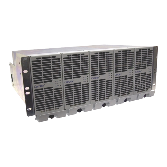
- Page 1 Cordex 24-3.1kW Modular Switched Mode Rectifier System Installation & Operation Manual Part # 030-803-J0 Effective: 02/2014 Your Power Solutions Partner member of The Group ™...
- Page 3 Keep it in a safe place. Review the drawings and illustrations contained in this manual before proceeding. If there are any questions regarding the safe installation or operation of this product, contact Alpha Technologies or the nearest Alpha representative. Save this document for future reference.
- Page 4 Electrical Safety WARNING! Hazardous voltages are present at the input of power systems. The DC output from rectifiers and batteries, though not dangerous in voltage, has a high short-circuit current capacity that may cause severe burns and electrical arcing. Before working with any live battery or power system, follow these precautions: •...
- Page 5 Inspeccione los dibujos y las ilustraciones contenidas en este manual antes de continuar. Si existe cualquier pregunta relacionada con la instalación u operación segura de este producto, póngase en contacto con Alpha Technologies o con su representante de Alpha más cercano. Guarde este documento para referencia futura.
- Page 6 Seguridad Eléctrica ¡ADVERTENCIA ! Hay voltajes peligrosos en la entrada de los sistemas de alimentación. La salida de CC de rectificadores y baterías, si bien no es peligrosa en cuanto al voltaje, cuenta con una alta capacidad de conducción de cortocircuito que puede causar quemaduras graves y arcos eléctricos.
- Page 7 En cas de questions sur l'installation ou le fonctionnement en toute sécurité de ce produit, contactez Alpha Technologies ou le représentant d'Alpha le plus près. Conservez ce document pour référence future. Symboles de Sécurité...
- Page 8 Sécurité Electrique AVERTISSEMENT ! Des tensions dangereuses sont présentes à l’entrée des systèmes électriques. La sortie CC des redresseurs et des batteries, bien que non dangereuse en termes de tension, a une capacité de courant de court-circuit élevée qui peut causer de graves brûlures et des arcs électriques.
- Page 9 Bewahren Sie es an einem sicheren Ort auf. Sehen Sie sich die Zeichnungen und Illustrationen in diesem Handbuch genau an, bevor Sie fortfahren. Sollten Sie Fragen zur sicheren Installation oder zum Betrieb dieses Produkts haben, wenden Sie sich bitte an Alpha Technologies oder den nächstgelegenen Alpha-Vertreter. Bewahren Sie dieses Dokument für den zukünftigen Gebrauch auf.
- Page 10 Elektrische Sicherheit WARNUNG! Am Punkt der Stromeinspeisung liegen gefährliche Spannungen vor. Der Gleichstromausgang von Gleichrichtern und Batterien weist zwar keine gefährliche Spannung auf, die Kurzschlussstrom-Kapazität ist jedoch sehr hoch, was zu ernsthaften Verbrennungen und Lichtbögen führen kann. Befolgen Sie die folgenden Vorsichtsmaßnahmen, bevor Sie mit einer spannungsführenden Batterie oder einem Stromversorgungssystem arbeiten: •...
- Page 11 (030-736-20 non-RoHS) The following documents and drawings are included in this manual to provide the necessary information re- quired for installation, operation and fault diagnosis of the unit: • Specifications, Cordex 24-3.1kW: 010-601-B1 Rev B • Specifications, CXCM4: 018-586-B1 (018-574-20 non-RoHS) •...
-
Page 12: Table Of Contents
ABLE OF ONTENTS ................................1 NTRODUCTION Scope of the Manual ............................. 1 Product Overview ............................1 Part Numbers and List Options ........................2 ..............................3 ECTIFIER EATURES Front Panel ..............................3 Rear Panel ..............................4 True Module Fail Alarm ..........................4 Heat Dissipation ............................ - Page 13 IGURES Figure 1–Cordex 24-3.1kW modular switched mode rectifier system ................1 Figure 2–Cordex 24-3.1kW modular switched mode rectifier (shown with optional charcoal finish) ....... 3 Figure 3–Cordex CXCM4 model system controller front panel (shown with optional gray finish) ........7 Figure 4–LVD control card option ...........................
-
Page 14: Introduction
Introduction Scope of the Manual This instruction manual explains the installation, interconnection, and operation of Alpha Technologies’ Cordex 24-3.1kW modular switched mode rectifier system. NOTE: To aid the user with installation, frequent reference is made to drawings located at the rear of the manual. -
Page 15: Part Numbers And List Options
Module blank ..............................List 90 Cordex 24-3.1kW 19” shelf, flush mounting (see also mid-mounting options), AC input, single phase ..030-804-20 Basic shelf, may be equipped with up to five Cordex 24-3.1kW modules** (non-RoHS 030-737-20) ....*List 0 24V system ................................ *List 1 Mid-mounting, 19”... -
Page 16: Rectifier Features
Rectifier Features Front Panel LEDs Thumbscrew Figure 2–Cordex 24-3.1kW modular switched mode rectifier (shown with optional charcoal finish) 2.1.1 LEDs The front panel LEDs provide: • Rectifier status summary, • Rectifier software upgrade in progress indication, • Locate module pattern. -
Page 17: Rear Panel
The LED remains off in the absence of an alarm. If the unit output is not connected to a battery or parallel rectifier, the LED will extinguish if no AC power is present. 2.1.1.4 LED Activity During Software Upload When a rectifier software upload is in progress, the LEDs will behave in a distinctly different way to indicate new rectifier software is being transferred from the CXC. -
Page 18: Wide Ac Range
output current. If temperature continues to increase, a shutdown of the rectifier is initiated. The rectifier shall restart automatically if the temperature has returned to a safe level. Wide AC Range A minor alarm is generated when the AC input voltage drops below specification. Rectifier output power is reduced linearly between 176Vac and 150Vac to 75% of the rated output power (the unit will deliver derated output power down to 80Vac). -
Page 19: Battery Eliminator Operation
2.13 Battery Eliminator Operation Rectifier modules maintain all specifications (except where indicated) with or without a battery attached in parallel to the output; however, if a battery or another module supplying DC voltage in parallel is not present, there will be no monitoring or control activity if there is an AC power failure or input fuse failure. -
Page 20: Cxcm4 Features
CXCM4 Features The CXCM4 (Cordex Controller, Modular, 4RU) is mounted in the rectifier system shelf and brings advanced monitoring technology to the Cordex series of rectifiers. This compact system controller is designed for seamless operation and set up of Alpha power systems and is equipped with the complete range of Cordex software features, including the following: •... -
Page 21: Analog Input Channels
3.1.2 LEDs The CXCM4 has three LEDs located on the front panel. These are used to display the alarm status of the power system, CXCM4 progress and status during startup, file transfers and lamp tests. 3.1.2.1 Alarm Conditions The CXCM4 illuminates the LED that corresponds to the system alarm status. The following show the corresponding alarm status for each LED color: Green –... -
Page 22: Digital Input Channels
3.2.3 Temperature Inputs Two temperature input channels, T1 and T2, provide monitoring of battery temperature and temperature compensation (temp comp) or room/ambient temperature. A voltage is supplied to these terminals to power the temperature sensors. Digital Input Channels The CXCM4 can accommodate up to four channels and can monitor digital alarm/control signals from rectifiers, converters and many other types of equipment. -
Page 23: Inspection
If the original container is unavailable, make sure the product is packed with at least three inches of shock-absorbing material to prevent shipping damage. NOTE: Alpha Technologies is not responsible for damage caused by the improper packaging of returned products. Check for Damage Prior to unpacking the product, note any damage to the shipping container. -
Page 24: Installation
Installation This chapter is provided for qualified personnel to install the product, which shall be mounted in a clean and dry environment. NOTE: To aid the user with installation, frequent reference is made to drawings located at the rear of the manual. Safety Precautions WARNING Hazardous voltages are present at the input of power systems. -
Page 25: Cxcm4 Module Insertion/Removal
CXCM4 Module Insertion/Removal Insert by placing the controller on the shelf bottom and sliding the module into the CXCM4 connection interface (inside of the shelf, see drawing 747-275-08). Apply pressure on the metal faceplate to engage the rear connectors. Tighten the screw on the bottom of the faceplate to secure the module to the shelf. NOTE: Do not force a module into position if it does not seat properly. -
Page 26: Wiring And Connections
Wiring and Connections This chapter provides cabling details and notes on cable sizing for DC applications with respect to the Alpha Cordex 24-3.1kW modular switched mode rectifier system. Safety Precautions WARNING Hazardous AC voltages may be present. Ensure power at the AC service panel is off before attempting work on the AC connections. -
Page 27: Calculating Output Wire Size Requirements
Replace rear cover(s) once all connections have been completed. 6.5.1 Single Phase Remove the metal covers (2 places) from the rear of the shelf to expose the AC input terminal blocks, L1 and L2 for each rectifier. Each terminal pair relates to an individual power module as marked. 6.5.2 Dual Three Phase (23”... -
Page 28: Can Serial Ports
CAN Serial Ports Two CAN Serial ports (modular jacks with offset latches), are provided for communications with Alpha’s Cordex rectifiers and other CAN-enabled equipment. These are located on the left side of the shelf (as viewed from the front). Daisy-chain from shelf to shelf (CAN OUT of one shelf to CAN IN of another) as necessary and ensure that only the last shelf is terminated. -
Page 29: Network Connection And Remote Communications Via Cxc
Network Connection and Remote Communications via CXC The Cordex system can be set up, monitored and tested via ETHERNET 10/100 Base-T serial data connection. The communication protocol supports a web interface. NOTE: Pinouts are shown in customer connections drawing for CXCM4. Some standard scenarios are described below: 6.9.1 Ethernet Port for Network Connection (Standard Network Cable) -
Page 30: Signal Wiring Connections For Cxcm4
6.10 Signal Wiring Connections for CXCM4 The CXCM4 (specifications 018-586-B1) requires an adapter for modular installation (drawing 747-275-08). NOTE: To aid the user with installation, frequent reference is made to drawings located at the rear of this manual. Custom configurations may be detailed within the Alpha power system documentation package. For terminal block connections, the recommended wire sizes are 0.823 to 0.129mm (#18 to #26 AWG) for the temperature range of 0 to 50 deg. -
Page 31: Figure 8-Showing Digital Input Connection Method
Figure 8–Showing digital input connection method 6.10.2.2 Programming the Digital Input The digital input channels can be programmed for “active high” or “active low.” Active high indicates “alarm on the presence of a ground signal” and active low indicates “alarm on the removal of a ground signal.”... -
Page 32: Operation
Operation Main Rectifier States Rectifier operation can be broken up into five main states: 1. Off, 2. Start delay, 3. Soft start, 4. Normal operation, 5. Turning off. Each state is characterized as being distinct and necessary for the operation of the rectifier. These states are briefly described below. -
Page 33: Main Rectifier Modes
Main Rectifier Modes In addition to Main Rectifier States, there is a set of Main Rectifier Modes. These modes can be divided into two categories as follows: 7.2.1 Output Voltage Modes Voltage modes can be thought of as modes that, under software control, can directly adjust the output voltage. The qualification of ‘under software control’... -
Page 34: Factory Ranges And Defaults
Remote Shutdown Enable/Disable Enable Ramp Test Enable/Disable Enable Table D–Cordex 24-3.1kW factory ranges and defaults NOTE: OVP cannot be set below the present system/FL/EQ/BT voltage setting or the safe mode voltage of 25.7V. 030-803-J0 Rev B Page 21 of 26... -
Page 35: System Startup
System Startup After completing the shelf wiring and installation, perform the following startup and test procedure to ensure proper operation: Check System Connections • Ensure AC is off, battery is disconnected, and all power modules are removed from the shelf. •... -
Page 36: Maintenance
Maintenance Although very little maintenance is required with Alpha systems, routine checks and adjustments are recommended to ensure optimum system performance. Qualified service personnel should do repairs. The following table lists a few maintenance procedures for this system. These procedures should be performed at least once a year. -
Page 37: Mov Replacement
1. Shut off the unit and unscrew the front fastener that secures the power module to the shelf. 2. Slide the module 10 cm (4”) out of the shelf and wait two minutes for module capacitors to discharge. 3. Remove the four screws (two each side) that secure the front panel to the module chassis. 4. -
Page 38: 10 Warranty
10.1 Warranty Alpha Technologies Ltd. warrants all equipment manufactured by it to be free from defects in parts and labor, for a period of two years from the date of shipment from the factory. The warranty provides for repairing, replacing or issuing credit (at Alpha’s discretion) for any equipment manufactured by it and returned by the customer to the... -
Page 39: Acronyms And Definitions
Acronyms and Definitions Alternating current ANSI American National Standards Institute American Wire Gauge British thermal unit Controller area network Canadian Electrical Code Canadian Standards Association Cordex™ series; e.g., CXC for Cordex System Controller Direct current DHCP Dynamic Host Configuration Protocol Electronic Industries Alliance Electromagnetic compatibility Electromagnetic interference... - Page 40 Any changes or modifications to this equipment not expressly described in this manual could void the FCC compliance. Alpha Technologies Ltd. 010-601-B1 Rev B Printed in Canada. © 2012 Alpha Technologies Ltd. ALPHA and CORDEX are trademarks of Alpha Technologies Ltd. All Rights Reserved. Page 1 of 3...
- Page 41 >350,000 hours ground benign @ 30°C (86°F) Dimensions: Refer to Outline drawings Alpha Technologies Ltd. 010-601-B1 Rev B Printed in Canada. © 2012 Alpha Technologies Ltd. ALPHA and CORDEX are trademarks of Alpha Technologies Ltd. All Rights Reserved. Page 2 of 3...
- Page 42 The above information is valid at the time of publication. Consult factory for up-to-date ordering information. Specifications are subject to change without notice. Alpha Technologies Ltd. 010-601-B1 Rev B Printed in Canada. © 2012 Alpha Technologies Ltd. ALPHA and CORDEX are trademarks of Alpha Technologies Ltd. All Rights Reserved. Page 3 of 3...
- Page 43 0 to 95% non-condensing Elevation: -500 to +4000m (-1640 to 13124 ft) Alpha Technologies Ltd. 018-586-B1 Rev B Printed in Canada. © 2012 Alpha Technologies Ltd. ALPHA and CORDEX are trademarks of Alpha Technologies Ltd. All Rights Reserved. Page 1 of 2...
- Page 44 The above information is valid at the time of publication. Consult factory for up-to-date ordering information. Specifications are subject to change without notice. Alpha Technologies Ltd. 018-586-B1 Rev B Printed in Canada. © 2012 Alpha Technologies Ltd. ALPHA and CORDEX are trademarks of Alpha Technologies Ltd. All Rights Reserved. Page 2 of 2...
- Page 45 REVISIONS REV BY DESCRIPTION DATE APPD 16.10 408.9 15.28 388.2 6.97 177 6.55 166.4 6.05 153.7 5.05 128.3 REAR VIEW 6.00 152.4 MODULES ARE HIDDEN LIST 23 23" MID-MOUNT 1.63 41.5 .88 22.3 TOP VIEW LIST 25 (SHOWN WITH LIST 82 - OUTPUT BARS) 23"...
- Page 46 LIST 89 - KYDEX REAR COVER 17.17 436 TOP VIEW (SHOWN WITH LIST 82 - OUTPUT BARS) REAR ISOMETRIC VIEW THESE DESIGNS AND SPECIFICATIONS ARE THE PROPERTY OF ARGUS TECHNOLOGIES AND SHALL NOT BE COPIED OR USED FOR MANUFACTURING WITHOUT ITS WRITTEN CONSENT. SIDE VIEW WH/EOF N.T.S.
- Page 47 REVISIONS REV BY DESCRIPTION DATE APPD ADDED MID-MOUNT OPTIONS S.D.W. 2007/01 16.10 408.9 15.28 388.2 6.97 177.0 6.55 166.4 6.11 155.1 5.11 129.7 REAR VIEW MODULES ARE HIDDEN 23.6 TOP VIEW 010-572-10 LIST 90 3.1kW MODULE MODULE BLANK 12.7 LIST 89 1.75 44.5 KYDEX COVER...
- Page 48 17.16 436.0 5.03 127.7 .93 23.6 LIST 23 23" CABINET MID MOUNT TOP VIEW - LIST 19 - 19" MID MOUNT 6.97 177.0 6.97 177.0 6.74 171.1 6.74 171.1 5.49 139.3 5.49 139.3 4.99 126.6 3.74 94.9 3.24 82.2 1.99 50.4 1.49 37.7...
- Page 49 REVISIONS REV BY DESCRIPTION DATE APPD AC WIREWAY (2 PLACES) 1.3 [34] HOLE FOR SWITCH SETTING FOR CAN TERMINATION CUSTOMER SUPPLIED 1" SEE DETAIL 'A' AC WIREWAY CONDUIT FITTING BLANK PLATE TERMINATED REAR VIEW - AC BACK COVER REMOVED UNTERMINATED PROTECTIVE EARTH TERMINAL 2 PLACES...
- Page 50 REVISIONS REV BY DESCRIPTION DATE APPD NEGATIVE (-) OUTPUT TERMINAL POSITIVE (+) DC WIRING OUTPUT TERMINAL 3/8" FLAT WASHER (CUSTOMER 3/8" LOCK WASHER SUPPLIED) 3/8-20 NUT 3/8" FLAT WASHER NEGATIVE (-) 3/8" LOCK WASHER OUTPUT TERMINAL 3/8-20 NUT NEGATIVE (-) BUS BAR (CUSTOMER SUPPLIED) 3/8"...
- Page 51 REVISIONS REV BY DESCRIPTION DATE APPD AC WIREWAY (2 PLACES) SWITCH SETTING FOR CAN TERMINATION AC WIREWAY 1.3 [34] HOLE FOR BLANK PLATE CUSTOMER SUPPLIED 1" SEE DETAIL 'A' CONDUIT FITTING TERMINATED UNTERMINATED REAR VIEW - AC REAR COVER REMOVED PROTECTIVE EARTH TERMINAL 2 PLACES...
- Page 52 3/8" FLAT WASHER NEGATIVE (-) 3/8" LOCK WASHER OUTPUT TERMINAL NEGATIVE (-) POSITIVE (+) 3/8-20 NUT OUTPUT TERMINAL OUTPUT TERMINAL 3/8" FLAT WASHER 3/8" LOCK WASHER 3/8-20 NUT DC WIRING (CUSTOMER NEGATIVE (-) BUS BAR SUPPLIED) (CUSTOMER SUPPLIED) POSITIVE (+) 3/8"...
- Page 53 REVISIONS REV BY DESCRIPTION DATE APPD 64 PIN CONNECTOR PIN OUT RESET SWITCH A32 B32 K1 - COM K1 - NO K2 - NO K1 - NC K2 - NC K2 - COM K3 - COM K3 - NO 32 PIN CONNECTOR K4 - NO K3 - NC K4 - NC...
- Page 54 REVISIONS REV BY DESCRIPTION DATE APPD #6-32x0.375 PH SCREW, LOCK AND FLAT WASHERS 747-275-20 ADAPTOR SECURE ADAPTOR INTO SHELF MODULE #1 SLOT CAN TERMINATION SWITCH ENABLE TERMINATION IN THE FINAL SHELF ON THE CAN BUS ONLY 3.1kW CORDEX SHELF BATTERY CONNECTION (+24V) ONLY REQUIRED WHEN USING BATTERY DISCONNECT DEVICE CXCM4 POWER AND RECTIFIER CAN...
- Page 56 Canada and USA: 1-888-462-7487 International: +1-604-436-5547 Visit us at www.alpha.ca Due to continuing product development, Alpha Technologies reserves the right to change specifications without notice. Copyright © 2014 Alpha Technologies. All Rights Reserved. Alpha® is a registered trademark of Alpha Technologies.
Need help?
Do you have a question about the Cordex 24-3.1kW and is the answer not in the manual?
Questions and answers