
Related Manuals for golmar SAR-GB2


Summary of Contents for golmar SAR-GB2
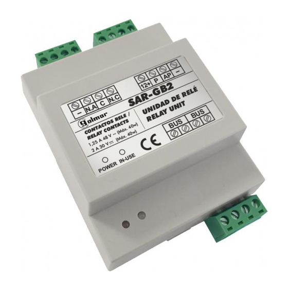
- Page 1 RELAY UNIT SAR- B C N.C P AP SAR-GB2 CONTACTOS RELE / UNIDAD DE RELÉ RELAY CONTACTS RELAY UNIT 1,25 A 48 V ~ (Máx. 40w) 2 A 30 V (Máx. 40w) POWER IN-USE Code 50121952 SAR-GB2 N REV.0117...
-
Page 2: Table Of Contents
Do not overtighten the screws on the terminal block. Install the SAR-GB2 relay unit in a dry and protected location free from the risk of dripping or splashing water. Install the SAR-GB2 relay unit and SAR-12/24 together with the FA-GB2A power supply unit. -
Page 3: Operating Modes
This operating mode allows activation of a Golmar additional alternating lock release. This lock release is activated as lock release 1 or lock release 2 and with the panel that has been assigned (through configuration in SAR-GB2) during a call or communication process. -
Page 4: Description Of Sar-Gb2 Relay Unit
Detail of the installation of the relay unit: Install the relay unit in a dry and protected location free from the risk of dripping or splashing water. Install the SAR-GB2 relay unit and SAR-12/24 together with the FA-GB2A power supply unit. C N.C... -
Page 5: Operating Mode Configuration
The relay unit is factory-setting in “lock release relay” operating mode. Operating mode configuration: Step Remove the power supply from the SAR-GB2 relay unit by removing the relay unit Bus connector (The power supply status LED will turn off). Step Set DIP1 to ON, DIP2 to ON and DIP3 to OFF. -
Page 6: Relay Unit Lock Release Activation Time
Relay unit lock release activation time. Configuration: Step Remove the power supply from the SAR-GB2 relay unit by removing the relay unit Bus connector (The power supply status LED will turn off). Step Connect the power supply to the SAR-GB2 relay unit by inserting the relay unit Bus connector. (LED showing the power supply status will turn on). -
Page 7: Operating Mode Description "Stairs Light Activation Relay
Relay unit light activation time: Configuration: Step Remove the power supply from the SAR-GB2 relay unit by removing the relay unit Bus connector (The power supply status LED will turn off). Step Connect the power supply to the SAR-GB2 relay unit by inserting the relay unit Bus connector. (LED showing the power supply status will turn on). -
Page 8: Wiring Diagrams
Neutral point of the power supply of the stairs light is connected in series through the relay contacts of the SAR-12/24. IMPORTANT: For the description, installation, configuration and programming of the system, see the corresponding manual. Golmar additional alternating lock release relay: Mains 100~240Vac C N.C... -
Page 9: Not S
RELAY UNIT TSAR-GB2 NOT S:... - Page 10 C/ Silici, 13 08940- Cornellá de Llobregat SPAIN Golmar se reserva el derecho a cualquier modificación sin previo aviso. Golmar se réserve le droit de toute modification sans préavis. Golmar reserves the right to make any modifications without prior notice.
Need help?
Do you have a question about the SAR-GB2 and is the answer not in the manual?
Questions and answers