Table of Contents
Advertisement
Advertisement
Table of Contents

Summary of Contents for Jetco TTS-1000
- Page 1 TS-1000 & TTS-1000 Torque Tester Operation Manual Rev 2 2008...
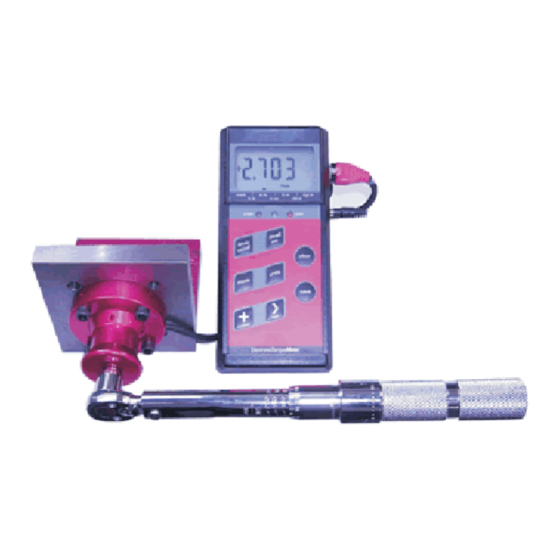
- Page 2 Use it as a high end torque calibrator or bring it to the work site to accurately apply torque to fasteners. With the JETCO Electronic Torque Meter you only have to buy one electronic module. Simply add ranges as you need them by purchasing additional torque transducers.
-
Page 3: Table Of Contents
Table of Contents Feature Overview..4 Keypad functions..5 General Operation Suggested mounting positions..6 Quick Start..7 To change the mode of operation..7 To change the units of measure..7 To turn limits on/off..7 To set a new target torque when % is the default..8 To recall the last cleared torque..8 To save a torque value to memory..8 To view the attached transducer information..8... -
Page 4: Feature Overview
Features User Friendly LCD with Software selectable filters Industry leading triple numeric display Three reset modes: Auto Manual Hi/Low Timed or % tolerance shown at all times Super large 5/8 high digits Track Peak First peak mode Memory for up to 1350 Auto convert Custom transducer mode torque data. -
Page 5: Keypad Functions
Keypad Functions Press once to turn limits on or off Press and hold to set new limits Press to change modes (press save key to save new mode) Recall last cleared torque Press and hold to send data on display to computer or printer Press to view current torque in other units Increases value of blinking digit... -
Page 6: Suggested Mounting Positions
Suggested mounting positions Loosen the 4 locking screws prior to adjusting Typical bench mounting Over a ledge Under a shelf Vertical wall Reverse bracket and Belt mount hang on a thin shelf... -
Page 7: Quick Start
General Operation Quick Start: 1. Turn off the power. 2. Plug in the proper transducer- Turn on-wait for the display to show zero (do not apply torque during this time). The meter reads the transducer smart chip when turned on. 3. -
Page 8: To Set A New Target Torque When % Is The Default
To set a new target torque (When % is the default limits mode) 1. Press and hold the limits key for 1 second. (The current target torque shows with the first digit blinking). 2. Use the increase and next key(s) to set the new target torque (see “entering numbers”... -
Page 9: Menu Functions
Menu functions: There are many settings that can be changed or viewed with the menu function. 1. Activate the menu function by pressing the mode and units key at the same time (the display will show set-up). 2. Press the NEXT key to step through the various options. -
Page 10: To Send Memory To A Printer Or Computer
To Send memory to a printer or computer 1. Attach the torque meter serial communication cable to your printer or computer com port. (set thecom port baud rate to 4800,8,n,1,hardware). Refer to your computer manual for details on how to communicate with serial devices. -
Page 11: To Change The % Tolerance Value
Tolerance vs High Low (Go/No Go Calculation) … To select and change the % tolerance value from the current setting 1. Press the menu keys. 2. Press the next key 5 times or until “tolerance” shows. 3. Press the save key to select the tolerance function. 4. -
Page 12: To Change The Display Clear (Reset) Method
To change the display clear method 1. Press the menu keys. … 2. Press the next key 6 times or until the “Auto Reset” icon shows. 3. Press the save key to select the Auto Reset function. 4. Press the next key until: “AUt0”... -
Page 13: Entering Numbers
Entering Numbers When a number needs to be entered or changed a default value (or the last value entered) will be 000.0 shown. The active digit that can be changed will blink. Press the increase key to increase the value of the blinking digit. -
Page 14: Torque Sensors (Transducers) And Overload
Torque Sensors and OVERLOAD Torque transducers are designed to give years of reliable operation if treated properly. Torque transducers are sensitive electro-mechanical measurement devices and should be handled with care. Never over-torque a transducer beyond its usable range. It is good practice, when possible, to select a transducer that is at least 25% greater in range than the expected torque it will apply. -
Page 15: Transducer Mounting Positions
Always make sure the bench is strong enough and will not tip wen applying torque Bolting the bench to the ground may be necessary on higher range transducers. JETCO optional part # BKT-4 mounting bracket (transducers up to 600 ft.lb.). Make sure the cable is pointing down (4 O’CLOCK POSITION) when mounted on a... -
Page 16: Checking For Accuracy
Checking for accuracy The Torque Meter and torque transducers are factory calibrated and should be checked on a regular basis. We recommend that, provided the transducers are used according to this manual, they be re-certified yearly. Since the frequency of use, among other factors, may affect the calibration, the user must determine the best calibration interval. - Page 17 IMPORTANT! YOU MUST ALWAYS DO THE FOLLOWING: MOUNT THE TRANSDUCER SO THE CABLE IS POINTING DOWN. PUT THE METER IN TRACK MODE. 1. NEVER USE A TORQUE ARM THAT IS NOT BALANCED ABOUT ZERO. A HIGH PRE- LOAD,OR AN OPPOSITE DIRECTION PRE-LOAD REDUCES ACCURACY AND IS NOT INDICATIVE OF REAL APPLICATIONS.
-
Page 18: Calibrating And Bypassing The Smart Transducer Calibration Data
Calibrating the torque transducer: You can not change the information on the smart chip within the transducer. If the values on the chip need to be changed then one of two things MAY have happened: 1. The torque arm system, or the procedure, is introducing errors that when added are creating an out of tolerance situation (SEE ACCURACY CHECKING ABOVE).. - Page 19 3. Press the increase and key to make the digits read the full-scale range of the transducer you are going to calibrate. Press the save key 4. Now set the decimal position with the next key (keep pressing until you see the decimal point)..
-
Page 20: Selecting Custom Transducers
simply need to select the proper transducer number when selecting custom transducers. you do not have to re-select a smart transducer custom assigned number unless you have disconnected the transducer from the meter. You can repeat the above process adjusting the full scale value until the unit reads as accurately as you desire at any point on the scale. -
Page 21: Battery And Power
Battery and Power The torque meter uses either a common 9 volt battery (gives longest life) or a rechargeable 9 volt battery (supplied standard for convenience). Battery life depends significantly on the type of battery used. Non-rechargeable lithium ion 9- volt batteries may last up to 40 hours. -
Page 22: Specifications
Specifications: Standards: This tester when combined with JETCO torque transducers, is guaranteed to meet or exceed ANSI B107.29 Electronic Tester, Hand Torque Tools standards. Range and Display: Direct reading triple numeric LCD display with large 4 digit primary display (5/8” high) and two additional 4 digit displays. -
Page 23: Troubleshooting
Troubleshooting: Meter reads “OPEN” when turned on: 1. Transducer is not plugged in. Plug in transducer 2. There is a significant load on the transducer when the meter is powered on. Remove load (such as hanging wrench). 3. The transducer or cable may have been damaged. Return for repair. -
Page 24: Spare Parts
Meter Kit Spare Parts: Description JETCO Part Number Case-Enclosure Z5 81-0040 Screws, Enclosure 220251 Bezel, LCD cover 810041-3 Keypad 810043-2 PCB Assembly 810044 810023 Battery, 9 Volt 45-0001 Stand, Adjustable 810046 Cable, Rs232 065150 Adapter, Serial-RJ6 Rs232 772084 Power Supply, 9V, 300mAh 97-0002 Cable, Transducer (up to 600 ft.lb.) -
Page 25: Transducer Information And Specifications
JETCO Torque Transducer Information (transducers sold separately): Sensor Material: 4140 High Modulus Alloy Steel Modulus of Elasticity: 30,000000 psi Yield Strength: 200,000 PSI Thermal Expansion: 6.5 ppm/ Degree F Density: .283 lb/in3 Hardness: 42-48 Rc Torque Sensor Housing: Material: 6061 Aluminum... - Page 26 Internal male drive Replaceable female-female drive adapter The new JETCO line of bench mount torque transducers come with a replaceable female-female drive adapter. This allows the user to use different drive sizes with each transducer. Each transducer is supplied with one female-female adapter with the typical square size for that range:...
- Page 27 Bench Mount Dimensions Up to 600 ft.lb. Hole Size Ø B.C. 45º Dimension (in) Part Number Hole Weight Internal Male Supplied Adapter Size Drive Size (Female x Female) BMI-50 2.75 2.175 .275 1/4” 1/4 x 1/4 BMI-100 2.75 2.175 .275 1/4”...
-
Page 28: Safety Warnings
Safety Warnings Always wear safety glasses when operating this torque meter. Always use the proper range transducer for the application. Over torque may result in damage to the transducer or breakage resulting in personal injury. Under torque may result in an incorrectly tightened fastener that could loosen resulting in failure at a later date.
Need help?
Do you have a question about the TTS-1000 and is the answer not in the manual?
Questions and answers