
Related Manuals for Clarke EPC1200


Summary of Contents for Clarke EPC1200
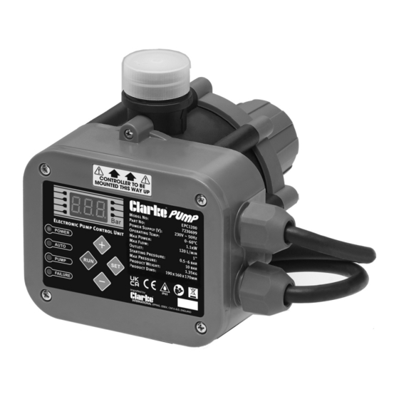
- Page 1 ELECTRONIC PUMP CONTROLLER MODEL NO: EPC1200 PART NO: 7230699 OPERATION & MAINTENANCE INSTRUCTIONS ORIGINAL INSTRUCTIONS GC06/22...
- Page 2 2. It protects the pump from running dry. • The EPC1200 controller has a built in safety circuit which switches the pump off when there is no water flow. • The controller performs pump control operations automatically.
-
Page 3: Working Modes
• Dry mode protection can re-start the pump if no flow after 48 hours to discourage blockages. • The digital display can be used to test and display starting pressure. WORKING MODES • In Automatic mode: the controller can automatically adjust the starting pressure according to the pressure in the pipeline and can monitor the pipeline pressure at any time. -
Page 4: Water Connection
(m) head (m) ELECTRICAL CONNECTIONS The EPC1200 controller is fitted with two cables. 1. One is fitted with a standard 13 amp plug. • When connected to the mains supply, this cable carries the supply to both the controller and the pump. -
Page 5: Mechanical Installation
MECHANICAL INSTALLATION You should always fit a non-return valve to the suction line. (A foot valve and filter are available from your CLARKE dealer). Parts & Service: 020 8988 7400 / E-mail: Parts@clarkeinternational.com or Service@clarkeinternational.com... -
Page 6: Wiring Connections
WIRING CONNECTIONS CONNECTING THE EPC1200 CONTROLLER TO DIFFERENT PUMPS Parts & Service: 020 8988 7400 / E-mail: Parts@clarkeinternational.com or Service@clarkeinternational.com... -
Page 7: Extension Cables
ELECTRICAL PLUGS AND CABLES WARNING: READ THESE ELECTRICAL SAFETY INSTRUCTIONS THOROUGHLY BEFORE CONNECTING THE PRODUCT TO THE MAINS SUPPLY. Connect the mains lead to a standard, 230 Volt (50Hz) electrical supply through an approved 13 amp BS 1363 plug or a suitably fused isolator switch. If the plug has to be changed because it is not suitable for your socket, or because of damage, it must be removed and a replacement fitted, following the wiring instructions shown below. -
Page 8: Controls And Displays
CONTROLS AND DISPLAYS Name Description FAILURE 1. Light ON = lack of water 2. Light OFF = water supply normal 3. Twinkling light means lack of water. The pump will stop and re-start. PUMP 1. Light ON = pump working 2. -
Page 9: Setup And Operation
SET-UP AND OPERATION SET THE WORKING MODE In automatic mode the AUTO light will be on. Press the SET button for 4 seconds and the AUTO light will go off and the unit will be in normal mode. Press the SET button for 4 seconds and the unit will return to AUTO mode. SET THE STARTING PRESSURE In AUTO mode, the controller will set a starting pressure according to the pipeline pressure. -
Page 10: Running The Unit
MAINTENANCE AND REPAIRS Although a component diagram is included, spare parts may be obtained from your CLARKE dealer and the work may be better left to their technicians. Parts & Service: 020 8988 7400 / E-mail: Parts@clarkeinternational.com or Service@clarkeinternational.com... -
Page 11: Troubleshooting
TROUBLESHOOTING Problem Causes related to the controller Other possible causes The pump Internal PCB is broken Voltage is less than 200 v does not start Pump jammed Cables incorrectly connected The pump Internal PCB is broken. Pipeline leaks does not stop Check valve is stuck Water contains materials in suspension. - Page 12 • The 1HP SPP10A 750W swimming cartridge for use with the various pool pump is a self priming pump Clarke water pumps including the designed to re-circulate water to SPP swimming pool pump range and from the pool via a filtration &...
-
Page 13: Declarations Of Conformity
DECLARATIONS OF CONFORMITY Parts & Service: 020 8988 7400 / E-mail: Parts@clarkeinternational.com or Service@clarkeinternational.com... -
Page 14: Component Parts
COMPONENT PARTS Parts & Service: 020 8988 7400 / E-mail: Parts@clarkeinternational.com or Service@clarkeinternational.com... - Page 15 COMPONENT PARTS Description Description Nameplate Main housing Screw Check valve baffle Panel Inner clamp Panel seal Diaphragm Display board Outer clamp Screw Screw Display board connection Top cap PCB with components Cap spring Screw Top cap core Pressure sensor clamp Screw Pressure sensor Head moulding...
Need help?
Do you have a question about the EPC1200 and is the answer not in the manual?
Questions and answers