Table of Contents
Advertisement
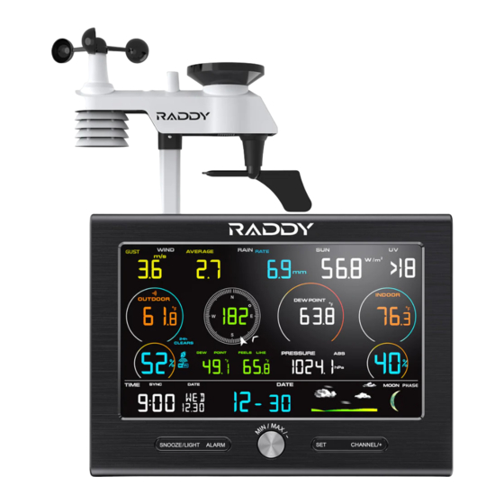
L7 Professional Lora WiFi Weather Station
1. Introduction..........................................................................3
2. Warnings and Cautions........................................................3
3. Getting Started.....................................................................3
3.1 Parts List.........................................................................3
3.2 Recommend Tools.........................................................6
3.3 Sensor Assembly Set Up................................................6
3.3.1 Install Integrated Outdoor Sensor Battery................6
3.4 Display Console............................................................9
3.4.1 Layout of Display Console.....................................9
3.4.2 Setup the Display Console ....................................11
3.4.3 Connect Sensors with Display Console.................12
3.5 Sensor Operation Verification.......................................13
3.6 WiFi Setup Guide.........................................................14
4. Sensors Pre-Installation.....................................................14
4.1 Test the Sensors Before Installation.............................14
4.2 Site Survey Before Installation......................................14
4.3 Best Practices for Wireless Communication.................15
5. Final Installation of Sensors...............................................16
5.1 Integrated outdoor Sensor Installation..........................16
6. Low Battery Icon................................................................22
7. Display Console Operation................................................22
7.1 Quick Display Mode......................................................22
7.2 Set (Program) Mode....................................................23
RADDY
User Manual
- 1 -
Advertisement
Table of Contents

Related Manuals for Raddy L7


Summary of Contents for Raddy L7
-
Page 1: Table Of Contents
RADDY L7 Professional Lora WiFi Weather Station User Manual 1. Introduction................3 2. Warnings and Cautions............3 3. Getting Started..............3 3.1 Parts List.................3 3.2 Recommend Tools............6 3.3 Sensor Assembly Set Up..........6 3.3.1 Install Integrated Outdoor Sensor Battery....6 3.4 Display Console............9 3.4.1 Layout of Display Console........9 3.4.2 Setup the Display Console ........11... - Page 2 7.3 Sensors Search Mode..........26 7.4 Max/Min Viewing and Reset Mode.......27 7.5 Snooze Mode...............28 7.6 Backlight Mode.............29 8. Alarm Mode................30 8.1 Alarm Triggered............30 8.2 View High/Low Alarm Value.........30 8.3 Setting the Alarms............31 8.4 Alarm and Key Beeper ON/OFF........33 9. Optional Calibration Mode..........33 9.1 Calibration of Temperature Mode.........34 9.2 Calibration of Humidity Mode........35 9.3 Calibration of Sensors Mode........36...
-
Page 3: Introduction
1.Introduction Thank you for your purchase of the Professional WiFi Wireless Weather Station. The following user guide provides step by step instructions for installation, operation and troubleshooting. 2.Warnings and Cautions Warning: Any metal object may attract a lightning strike, including your weather station mounting pole. Never install the weather station in a storm. - Page 4 Item Image Display Console Frame Dimensions (LxHxW): 7.6x5.5x1.1inch (193X140X28mm) LCD Dimensions (LxW): 6.3x 3.7inch (160X93mm) Integrated Outdoor Transmitter Dimensions: 13x11x5.9 inch (330x280x150mm) Foot Mounting (with pole insert) Dimensions: 4x3x1.5inch (101x76x37mm) Mounting Bracket Back Plate (pole mount) Dimensions: 3x2.96x0.79inch (76x75x20mm) Mounting Pole Dimensions: 11.8x1.18x0.79inch (300x30x20mm) - 4 -...
- Page 5 Item Image Pole mounting nuts (M3) / bolts Ø3) Pole mounting nuts (M5) / bolts ( Ø5) Tapping screws Manual Power Adapter Figure 1 - 5 -...
-
Page 6: Recommend Tools
3.2 Recommend Tools ● Precision screwdriver (for small Phillips screws) ● Compass or GPS (for wind direction calibration) ● Adjustable Wrench 3.3 Sensor Assembly Set Up Note: The outdoor sensor array must be powered and updating before powering up the console, or the console will stop scanning and connecting with the sensors. - Page 7 Locate the battery door on the bottom of transmitter as show in Figure 3. Note: Do not install the batteries backwards. You can permanently damage the outdoor sensors. The solar panel does not charge the batteries, so rechargeable batteries are not recommended.
- Page 8 Inserting 3 AA fresh batteries as show in Figure 5. Close the battery door. Make sure that the gasket (around the battery compartment) is properly seated in its trace prior to closing the door and Tighten the set screw. Note: We recommend installing Lithium AA batteries for outdoor sensors in cold weather environments.
-
Page 9: Display Console
Figure 6 3.4 Display Console 3.4.1 Layout of Display Console The following illustration shows the full segment LCD display for feature description purposes only in Figure 7 and will not appear like this during normal operation. - 9 -... - Page 10 Figure 7 1.Time and date 19.Integrated outdoor 2.Time alarm icon sensor Low power indicator 3.Internet SYNC Time icon 20.Temperature units (°F 4.Indoor temp and humidity or °C) display 21.Humidity units of 5.Indoor temperature and measure (%) humidity HI/LO alarm icon 22.
-
Page 11: Setup The Display Console
3.4.2 Setup the Display Console 1. Plug in the display console with power adapter. BL ON will display in the time area for three seconds when powered up. Conversely, The AC OFF icon will display . Note: It is recommended to plug in the power adapter to reduce the battery consumption and extend the service life. -
Page 12: Connect Sensors With Display Console
Figure 8 Replace the battery door, and unfold out the desk stand to place the console in the upright position Note: The battery is a back-up of weather station console, saving console settings when powered off from adapter. 3.4.3 Connect Sensors with Display Console Once the display console is powered up, it will automatically scan all the nearby Integrated Outdoor sensors. -
Page 13: Sensor Operation Verification
When connected with the Integrated Outdoor Sensor, the measured value (Outdoor temperature, humidity, wind direction, wind gust and average, rainfall, UV and Sunlight index, Dew point and feels like) will show up on the display console. Note: Make sure that the distance between weather station sensors and display console should be within 10ft (3m) to 100ft (30m). -
Page 14: Wifi Setup Guide
the same location (about 5 to 10’ (1.5 to 3 meters) apart). The sensors should be within 10% (the accuracy is ± 5%). Allow about 30 minutes for both sensors to stabilize. 3.6 WiFi Connection Guide For weather station models with WiFi function, you can start to set up wifi connection and weather data uploading. -
Page 15: Best Practices For Wireless Communication
3. Avoid wind and rain obstructions. The rule of thumb is to install the sensor array at least four times the distance of the height of the tallest obstruction. For example, if the building is 20ft (6m) tall, install 4 x (20 – 6)’ = 56ft (17m) away. Use common sense. -
Page 16: Final Installation Of Sensors
3. Line of Sight Rating. This device is rated at 300ft line of sight (no interference, barriers or walls) but typically you will get 100ft maximum under most real-world installations, which include passing through barriers or walls. 4. Metal Barriers. Radio frequency will not pass through metal barriers such as aluminum siding. - Page 17 This Professional Weather Station can be used in both the Northern and Southern Hemispheres. Prior to installation, you will need to calibrate the wind direction. Note: There are four alphabet letter of N, E, S and W around the wind direction.(N is North, E is East, S is South, W is West) Northern Hemispheres Southern Hemispheres...
- Page 18 South North Figure 9 Step 2: Console operation set to Northern Hemispheres( NOR in the time area) in Location division. (Check the detailed step of setting the time area in the part 17 of Chapter 7.2) 5.1.2 Southern Hemispheres (NOR) References. For Southern Hemisphere installations, ignore the direction (N, S, E, W), and face the solar panel to the North (and in a sunny position) when it comes to install the Integrated outdoor...
- Page 19 North South Figure 10 Step 2: Console operation set to Southern Hemispheres( SOU in the time area) in Location division. (Check the detailed step of setting the time area in the part 17 of Chapter 7.2) Note: The location division (NOR or SOU) on the Display Console and the directions of the sensor have to be adjusted to match with your real location.
- Page 20 Then, tighten the mounting pole to your existing mounting pole with the four bolts ( Ø5) and nuts (M5) , or fix it on the flat surface with four tapping screws, as show in Figure 11. Figure 11 - 20 -...
- Page 21 5.1.4 Mounting & Fixing the Sensor Vertically Fasten the integrated outdoor sensor to the mounting pole brackets with two foot-mounting screws Ø3 bolts and M3 nuts. Then, tighten the mounting pole to your existing mounting pole with the four bolts ( Ø5) and nuts (M5) , or fix it on the flat surface with four tapping screws, as show in Figure 12.
-
Page 22: Low Battery Icon
6. Low Battery Icon A low battery indicator icon is shown in the display window for integrated outdoor sensor. When the low battery icon appears (The Integrated outdoor sensor battery voltage is lower than 3.6V), replace the batteries in the sensor with fresh batteries. Be sure to never mix old and new batteries, and never mix battery types such as alkaline and lithium together. -
Page 23: Set (Program) Mode
1.Time, Time/Week and Date. Press the CHANNEL/+ or MAX/MIN/- key to toggle between time, time/week and date. 2. Indoor Temperature. Press the CHANNEL/+ or MAX/MIN/- key to toggle between temperature and dew point. 3. Rainfall. Press the CHANNEL/+ or MAX/MIN/- key to toggle between rate,1h, daily, week, month and total. - Page 24 Note: To exit the Set mode at any time, press the SNOOZE button of the display console. 1. Time SYNC(default: ON). Press the SET key again to set the network time sync. Press the CHANNEL/+ key or MAX/MIN/- key to switch between SYNC time ON/OFF of measure.
- Page 25 8. Change Year. Press the SET key again to set the calendar year. Press the CHANNEL/+ key or MAX/MIN/- key to adjust the calendar year. 9. Max/Min Clearing (default: ON). Press the SET key again to set the Max/Min clearing mode (CLR). The Max/Min can be programmed to clear daily (at midnight) or manually.
-
Page 26: Sensors Search Mode
15. Weather Icons Setting (default: partly cloudy). Press the SET key again to change the initial weather icon. Press the CHANNEL/+ key or MAX/MIN/- key to select the initial weather icon of Sunny, Cloudy, Partly Cloudy or Rainy. (For detailed information of this part please refer to 10.2) 16. -
Page 27: Max/Min Viewing And Reset Mode
press any buttons until the synchronization is complete. The remote search icon will display constantly for 3 minutes until the signal is reacquired. The ID Number of transmitter will appear in the date area. ID number is also labeled on the battery cover. Make sure you are receiving the correct transmitter if you have more than one unit working around. -
Page 28: Snooze Mode
Press the SNOOZE or MAX/MIN/- key to exit the min/max checking and reset mode, return to normal display mode. Note: The Maximum values will display the current values after reset. 7.4.2 Min Record Viewing and Reset Press the MAX/MIN/- key again (do not hold), the MIN icon will be displayed. -
Page 29: Backlight Mode
7.6 Backlight Mode 7.6.1 Adjustable Brightness of Backlight There are 3 levels of brightness of display backlight. When the backlight is on, press SNOOZE key to switch between the 3 levels. When backlight is off, press and hold the SNOOZE key for three seconds, the backlight will turn on permanently, and BL ON icon will be displayed for three seconds in the date area. -
Page 30: Alarm Mode
8. Alarm Mode The weather station includes the following alarms: 8.1 Alarm Triggered When an alarm condition is exceed, the alarm icon will flash (visual) and the alarm beeper will sound (audible). To silence the beeper, press any key. 8.2 View High/Low Alarms Value To view the current alarm settings, press the ALARM key to enter the alarm mode. -
Page 31: Setting The Alarms
8.3 Setting the Alarms Time (Alarm 1 and Alarm 2) Rate Rainfall Outdoor Temperature 24 Hour Rainfall Outdoor Humidity Absolute Pressure Outdoor AT(Apparent Relative Pressure Temperature) Indoor Temperature Outdoor Dew Point ... - Page 32 Press the SNOOZE key once at any time to return to the normal mode. After 30 seconds of inactivity, the alarm mode will time out and return to normal mode. The following is a list of the individual alarm parameters that are set (in order): 1.Alarm hour(alarm 1) 16.Wind Average HI alarm...
-
Page 33: Alarm And Key Beeper On/Off
Note: To prevent repetitive alarming of humidity, there is a 4% tolerance band in humidity alarm. For example, if you set the high alarm to 60% and silence the alarm, the alarm icon will continue to flash until the humidity falls below 56%, at which point, the alarm will reset and must increase above 60% to activate again. -
Page 34: Calibration Of Temperature Mode
measurement can be adjusted from the console to calibrate to a known source. Calibration is only useful if you have a known calibrated source you can compare it against, and is optional. This section discusses practices, procedures and sources for sensor calibration to reduce manufacturing and degradation errors. -
Page 35: Calibration Of Humidity Mode
To exit the temperature calibration mode at any time, press the SNOOZE/LIGHT button of the display console. If no operation is performed, the calibration mode will timeout in 30 seconds. 9.2 Calibration of Humidity Mode In normal mode, press and hold the SET and MAX/MIN/- keys at the same time for five seconds to enter into the humidity calibration mode. -
Page 36: Calibration Of Sensors Mode
9.3 Calibration of Sensors Mode In normal mode, press and hold the SET and ALARM keys at the same time for five seconds to enter the pressure, wind gust, rainfall and sunlight calibration mode. The letter “CAL” will appear at the bottom of the screen. Press the SET key to skip over a parameter to the next. - Page 37 Press the CHANNEL/+ key or MAX/MIN/- key to increase or decrease the relative pressure value (in increments of 0.01 inHg). Press and hold the CHANNEL/+ or MAX/MIN/- key for three seconds to increase or decrease rapidly. Press the ALARM key to reset current value. Example: The calibrated pressure sources measure 25.00 inHg.
- Page 38 pressure measurements less than 29.92 inHg are considered low pressure. To determine the relative pressure for your location, locate an official reporting station near from you (the internet is the best source for real-time barometer conditions, such as the website of Weather.com or Wunderground.com), and set your weather station to match the official reporting station.
- Page 39 of the tallest obstruction (for example, a 6m(20ft) house would require an installation 24m(80ft) away). In many instances, due to trees and other obstructions, this is not possible. The wind speed calibration allows you to correct for these obstructions. In addition to installation challenges, wind speed bearings (any moving part) wears over time.
-
Page 40: Other Features Of Display Console
rain (referred to as resolution). The accumulated rainfall can be compared to a sight glass rain gauge with an aperture of at least 4”. Note: that debris and insects can collect inside the tipping mechanism (they make a good spiders nest). Carefully remove the funnel and inspect the tipping mechanism for debris prior to calibration. -
Page 41: Weather Icons
cloudy) and when the pressure decreases, the weather degrades (cloudy to rain). The weather forecast is an estimation or generalization of weather changes in the next 24 to 48 hours, and varies from location to location. The tendency is simply a tool for projecting weather changing conditions and is never to be relied upon as an accurate method to predict the weather. -
Page 42: Moon Phase
Pressure is falling and the previous condition is partly Cloudy cloudy or Pressure is rising and the previous condition is rainy. Pressure is falling Rainy and the previous condition is cloudy 10.3 Moon Phase The following moon phases are displayed based on the calendar date. - Page 43 10.4.1 Feels Like Temperature Feels like temperature is a combination of Heat Index and Wind Chill. 1. Temperatures less than 4.4°C(40°F), the wind chill is displayed, as shown in the National Weather Service Wind Chill Table below: 2. Temperatures greater than 26.7°C(80°F), the heat index is displayed, as shown in the National Weather Service Heat Index Table below: - 43 -...
-
Page 44: Pressure Threshold Setting
10.4.2 Apparent Temperature (AT) AT is a linear regression that is not restricted, and is more appropriate to outside conditions because it includes wind, and was intended as an assessment of what exposed body surfaces feel like in cold, windy conditions. Regression equations of this universal scale are formulated for indoors, outdoors in shade but exposed to wind, and outdoors exposed to wind and solar radiation. -
Page 45: Restore Factory Default
The lower the level pressure threshold setting, the higher sensitivity for weather forecast changes. Locations that experience frequent changes in air pressure require a higher setting compared to locations where the air pressure is typically stagnant. 10.6 Restore Factory Default To reset the display console to factory default (WiFi network, Weather server and display), press the MAX/MIN/- key while plugging in power adaptor at the same time (Take out batteries... - Page 46 A. Remove the rain collector funnel B. Install the collector funnel. - 46 -...
-
Page 47: Trouble Shooting Guide
Replace the Integrated outdoor sensor once every 1-2 years 12. Trouble Shooting Guide Problem Solution Wireless remote not If any of the sensor communication is lost, reporting in to dashes (--.-) will be displayed on the screen. console. To reacquire the signal, press and hold the CHANNEL/+ button for 3 seconds, choose There are dashes the lost sensor and the remote search... - Page 48 icon will turn off, and the current values will be displayed. The maximum line of sight communication range is 1500m (4920ft) and 200m(656ft) under most conditions. Move the sensor assembly closer to the display console. If the sensor assembly is too close (less than 1.5m(5ft)), move the sensor assembly away from the display console.
-
Page 49: Specification
indoor and outdoor temperature to a known source. Indoor and Outdoor Allow up to one hour for the sensors to Humidity do not stabilize due to signal filtering. The indoor agree and outdoor humidity sensors should agree within 10 % (the sensor accuracy is ± 5 %). Use the calibration feature to match the indoor and outdoor humidity to a known source. - Page 50 90%) Outdoor 10 to 99% ± 5% (only Humidity guaranteed between 20 to 90%) UV Index 1 to 15+ ± 1 ± 1 Sunlight 0 to 200klux ± 15% ± 15% Rain 0 to 9999mm <15mm: <1000mm ±1 mm, (0.3mm) 15mm to >1000mm 9999mm:...
- Page 51 13.2 Wireless Specifications Integrated Outdoor Sensor Wireless Transmit Range 4920ft (in open air): (1500m) Integrated Outdoor Sensor Frequency: 915MHz Integrated Outdoor Sensor Data Update Period: 13.3 Power Consumption Display Console 3 x AAA 1.5V Alkaline or Lithium batteries (not included) Integrated Outdoor 3xAA alkaline batteries or Lithium batteries Sensor:...
Need help?
Do you have a question about the L7 and is the answer not in the manual?
Questions and answers